Table of Contents

Related Manuals for Sanding STS-750

Summary of Contents for Sanding STS-750
-
Page 1: Nomenclature And Functions
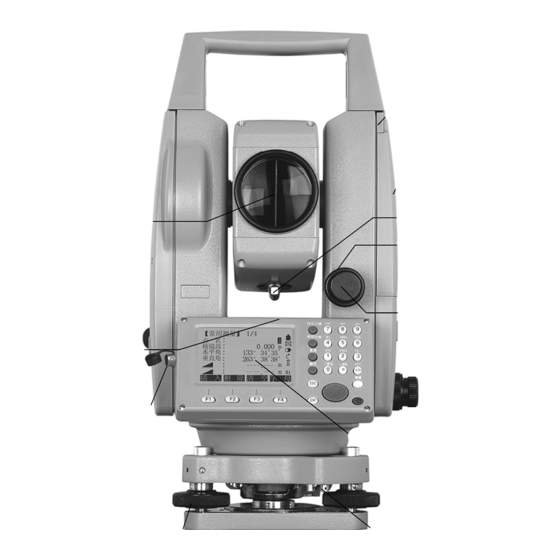
1. NOMENCLATURE AND FUNCTIONS 1.1 NOMENCLATURE (take STS-750 for example) Battery Locking Lever Battery SB-21 Collimator Objective Lens Vertical Clamp Screw Vertical Tangent Screw Plate Vial Data Port Display Adjustment Screw for Circular Vial Leveling Screw... - Page 2 Te scope Grip Telescope Focusing Knob Telesc Focusing Knob Instrument Eyepiece Center Mark Horizontal Clamp Screw Horizo ntal Tangent Sc Circular Vial Tribrach Lock Base...
-
Page 3: Measure
The chart above is the display screen,there may be a little difference on local language. 1.3 K EY BOARD It takes STS-750 for example here, STS-720 has not Numeric key. 1) Current operation section (available section) 2) Icon 3) Fixed key (have relevant fixed function) - Page 4 5) Navigation key 6) Soft key (Functions vary accor ding to the message displayed. 7) Soft function key (displa y relevant operation function, use to start-up relevant function. It can use to start-up figure and character function in STS-720) 8) Measure hot key (importan t key) 9) Power key FIXED KEY...
- Page 5 Soft Key: Function [All] To run angle and distance measurement mode, and record the data. [Meas] To run angle and distance measurement mode, but not record the data. [REC] To record the measurement data [NEZ] To open the coordinate inputting mode [List] To view list of all the options [Search]...
- Page 7 Battery power remaining icon: View the remaining power (The icon on the left represents 80% power remaining) Compensator status icons: Compensator is ON Compensator is OFF Character/Number inputting mode icons: Number Inputting Mode Character/Number Inputting Mode 1.9MENU TREE [Menu]>F1-F4 is to confirm the selected menu.
- Page 8 ----Codes ----Initializing Memory ----Memory Statistic MUNE (P2) Adjustment ----------------V- index ----Hz-collimation ----Horizontal Axis ----VO/Axis(Cons,list) ----lnst, Constant ----Tilt Parameter ----State Comm Parameters ------Baud Rate ----Data Bits ----Parity ----End Mark ----Stop Bit Data Transfer ------------Data Send ---- Job ---- Data ---- Format System Information ------------Battery ----Date ----Time...
- Page 9 2、PREPARATION FOR MEASUREMENT 2.1 UNPACKING AND STORE OF INSTRUMENT · Unpacking of instrument Place the case lightly with the cover upward, and unlock the case, take out the instrument. · Store of instrument Cover the telescope cap, place the instrument into the case with the vertical clamp screw and circular vial upwards (Objective lens towards tribrach), and slightly tighten the vertical clamp screw and lock the case.
- Page 10 ② Turn the leveling screw C to move the bubble to the center of the circular vial. 4) Precisely leveling by using the plate vial ① Rotate the instrument horizontally by loosening the Horizontal Clamp Screw and place the plate vial parallel to the line connecting leveling screw A and B , and then bring the bubble to the center of the plate vial by turning the leveling screws A and B.
- Page 11 Set instrument carefully on tripod, tighten the central connecting screw and adjust optical plummet to make the reticle distinctly. Hold the other two unfixed legs with both hands and adjust position of these two legs through observation of optical plummet. As it approximately aims at the station point, make all three legs fix on the ground.
- Page 12 · Batte ry Recharging Cautions: ☆ Battery should be recharged only with the charger SC-21 going with the instrument. ☆ R emove the on-board battery from instrument and connect it to battery charger. When the indica tor lamp on the battery charger is orang e, the recharging process has begun.
- Page 13 2.7 INPUTTING MODE STS-750 series Total Station has character numeric keypad, users th erefore can input fig and haracter directly. And since STS-720 is not equiped with numeric keypad, it needs to press [ENT]...
- Page 14 Each key of STS-750 Total Station Instrument is defined with three characters and one fig. Num er area Number area can only be i nput figures, press on keypad and figures will be displayed on the scree ALPH / NUMBER ARE The Alph/ number area can input characters and figures.
- Page 15 Use navigation key to delete character where the cursor is placed .7.1 INPUT CHARACTER Take STS-750 as an exam ple: each key is defined with three characters and a figure, as ente ring the character/fig. inputting mode, every time you press the keypad, a letter would occure at the cursor, and a fig occures by pressing four times.
- Page 16 【 Measure】 ① Press the key on numeric Pt ID : keypad to start inputting. As the RHT : 1.500 m sign in the lower right corner of HZ : 0°00′00″ the screen is [01], it means it is V : 90°00′00″...
-
Page 17: Table Of Contents
【Measure】 Pt ID : RHT: 1.500 m [F2] HZ: 0°00′00″ ②Press [F2], and then [F1] to Input [5] V: 90°00′00″ input fig. “5”. ---.--- m : Ⅰ ---.--- m : 【Meas 】 Pt ID : RHT : 1.500 m HZ: 0°00′00″... - Page 18 RHT : 1.500 m to the next item. [ENT] HZ: °00′00″ V: 90°00′00″ ---.--- m Ⅰ : : ---.--- m DIST RECORD ↓ 2.7.2 EDITTING CHARACTER Input characters can be edit. (here,only take STS-750 as an example) OPERATIONAL STEPS OPERATION DISPLAY...
-
Page 19: Measure】 1/4 Pt Id: 5
Set Hz TILT BEEP ∣← ※1)About the way to input character,please refer to “2.7.1 inputting cha racter” 。 2.7.3 DELETING CHARAC Input characters can be deleted.(only take STS-750 as an example) OPERATIONAL STEPS OPERATION DISPLAY 【Measure】 Pt ID : SANDIN RHT :... -
Page 20: Measure】 1/4 Pt Id
③Press [ENT] to confirm the 【Measure】 Pt ID : SANDING put . RHT : 1.500 m To restore the original value, [ENT HZ: 0°00′00″ press [ESC] to cancel the r [E V: 90°00′00″ amendment. ---.--- m : Ⅰ ---.--- m :... -
Page 21: Ptid
2.8 POINT SEARCHING Point searching is a comp hensive functi on, which use a procedure to search measurement oints or k nown points in interna l memo The searching scope can b e limited t o a ce rtain job or the whole internal mem ry The known points matchin g searching conditi on always emerge before measurem... - Page 22 ENH input】 【 B : SANDING ID: ------ ------ ③If the pointID you need does [F2] /E : ------. ------ m /N : ------. ------ m not exist in the job, press [F2] ------. ------ m : (ENH) to input coordinate.
-
Page 23: Wildcard Search
.9 WILDCARD SEARCH Use wildcard “*” represen those chara cters you are going to search. The wildcard searching is usually used in those conditions such as: not kn ow exactly the ointID you want to search or th e points are a a p ssel. - Page 24 3. ROUTINE MEASUREMENT .1 DISTANCE SURVEY CAUTIONS As the instrument is installed, turn on the power, then the total station is ready for operation. In displaying, you can invoke functions like fixed key, functional key and hot key. All displayed here are demonstrations. The local edition may have some differences from the asic one.
- Page 25 【EDM Settings】 ② As the cursor stays at EDM MODE, press navigation key EDM Mode: Tracking to choose the survey Prism: 30.0mm mod e. ATMOS GRID ↓ 【EDM Settings】 ③As finishing setting, Press [F3] (SET) to return to measure function. [F3] Quit the parameter?...
- Page 26 parameters. Press [F4] to return to e measure function ※1) The way to input prism const nt please ref er to “2.7 INPUTTING MODE’ ※2) T he scope of prism constant : -99mm , Step Length 0.1mm ~+99mm 3.2.3 Set Atmosphere Data efraction modules: The instrument will autom a ically correct t...
- Page 27 【Atmosphere Data】 ③Input refraction modulus. E.g.: RetrCorr: input 0.2, and press [ENT], Input 0. Temp : 20℃ Pressure : 1013.2 hP moving the cursor to Temp item. tmos PPM: 0 PPM [ENT] ※1),※2) BACK PPM=0 【EDM Settings】 ④ As the settings are finished, ress [F4] to store and return to EDM Mode:...
- Page 28 【Atmosphere Data】 Retr.Corr : 0.14 ②The current settings display on emp : 20℃ ressure : 1013.2 hPa the sreen, use navigation key Atmos PPM: 0 PPM to move the cursor to Temp item. BACK PPM=0 【 Atmosphere Data 】 Retr.Corr: 0.14ATUR ③Input temperature value, Input 26...
- Page 29 GRID FACTOR = height factor×scale Distance Calculation 1. GRID DISTANCE HDg = HD × Grid factor g:Grid distance HD :Ground distance 2.. G ROUND DISTANCE HD = Grid Note: 1 .Inputting range of scale:0.990000 ~ 1.010000. The default value: 1.00000 nputting range of average altitude: -9999.8 ~...
- Page 30 OPERATIONAL STEPS OPERATION DISPLAY 【EDM Settings】 ①In EDM setting screen, press EDM Mode: Tracking [F4] (↓) to display the second [F4] Prism: 30.0mm page menu, press [F1] to check [F1] signal distance measurement. ATMOS GRID ↓ SIGNAL MulCon ∣← 【EDM SIGNAL】 ②...
- Page 31 DIST RECORD ↓ 【 Measure 】 【 Measure 】 Pt ID : Pt ID : RHT : 1.500 m Code : SANDING HZ : 0°00′00″ RHT : 1.500 m Y/E : ---.--- m HZ : 0°00′00″ ---.--- m : Ⅰ...
- Page 32 【Measure】 Pt ID: RHT: 1.500 m ②Press [F4]( ↓) twice and turn to [F4] HZ : 50°20′00″ the third page of soft key. Press [F1] [F4] V : 82°00′00″ (SET Hz) to set horizontal angle. ---.--- m : Ⅰ ---.--- m :...
- Page 33 needed to modify, or press [F3](CLEAR)key and input the correct one ※2) If an error numerical value is i nputted (such as:70 ′)and screen do not answer the inputing a reasonable numerical key is needed to pres ※3)If the angle unit is degree, minute, and second, as part of ‘degree’s finished, you need to press·...
- Page 34 OPERATIONAL STEPS PERATION DISP 【Measure】 Input Pt ID Pt ID: ①Input pointID and prism height,as RHT: 1.500 m [ENT] finishing one item, press ENT to Input RHT HZ : 0°00′00″ move the cursor to the next inputting V : 90°00′00″ [ENT] area, to input the coding if in need.
- Page 35 IN GRAPH : 1) Aphonia area 2)Buzzer makes a brief interval beep. 3)Buzzer makes a constant beep. 3.3.4 Coding The code includes the information concerned wit h the recording point.In the course of after-processing ,with coding function,it is convenie nt to process in specified group.There are ome information concerned with coding in ‘FILE MANAGEMENT’.
- Page 36 【Measure】 Pt ID : Code: SANDING ②Input the code, and press [F4](↓) RHT: 1.500 m to display the second page soft key, Input the code HZ: 63°40′50″ here, the single coding being input V: 94°33′51″ Ⅰ : ---.--- m will not be enlisted in coding...
- Page 37 (or[DIST]+[RECORD])to keep it in survey data document together with those survey data as a single coding value,besides, the save sequence of coding data and practical survey data is also can be set ( to set in the item ‘Code record’ in ‘Main Settings’ and ‘Settings’). To set code save before:represents that as the survey is finished, the coding data will be saved before practical survey.
- Page 38 A:press[RECORD] ② The code well edited can be [F4] 【Measure】 kept in survey document. Pt ID: Code: RHT: 1.500 m A: Press [F1](RECORD) returning HZ: 0°00′00″ V: 90°00′00″ Ⅰ to measure function, set the input ---.--- m : code as the code of the present CODE ↓...
- Page 39 100 quick codings in all can be defined,you may create coding with code block manager provided by SANDING company, and transfer to the instrument .In the code block manager, each code can be arranged 1bit or 2bit digit exclusively If the code was not dispatched with a digit from“coding block manager”,the code will be...
- Page 40 OPERATIONAL STEPS OPERATION DISPLAY 【Measure】 Pt ID: Collimate to Code : --- --- CODING target ①Collimate to the prism center of point + RHT: 1.500 m the target point ,and input pointID Input HZ: 63°40′50″ 、 RHT prism height, press[TURN V:...
- Page 41 4. FUNCTIONS Several functions can be called up via [FNC] key. Functions can also be started directly from the different application. Each function from the Function menu can be assigned to the [USER] key. (See 4.4 “Main Settings”) Several functions: Light ON/OFF Switches display light on/off.
- Page 42 【Tilt Adjust】 ③ Tilt correction value is shown on the screen. If the value is within +3’, it X: -0°0′21″ is within the designed range of automatic compensator. Press Back [F4] to return to the function menu. If the value is beyond +3’, it needs to be leveled manually.
- Page 43 PERATION STEPS: OPERATIONAL STE ATION DISPLAY 【Function】1/4 ▼ 1 Level F2 Target Offset ①Press [FNC] to enter into the F3 Delete Last Record Function menu. F4 Main Settings 【Target Offset】 ② Press [F2] to enter into [F2] Input Offset! Target Offset function. T_Offset : 0.000m put the offset values (length,...
- Page 44 D splays the Rec. data beforehand. ⑥When “Oset After REC” is 【Measure】 selected: PtID: R.HT: 1.500 m [All] started, HZ: 0°00′00″ program will display the data V: 90°10′50″ : 5.568 m Ⅰ (the target point) which is 3.689 m : calculated plusing DIST...
- Page 45 OPERATION PROCUDURE OPERATIONAL STEPS OPERATION DISPLAY Function】1/4 【 ▼ F1 Level F2 Target Offset ①Press [FNC] to enter into the F3 Delete Last Record F4 Main Settings Function menu. Sure delete final record? ②Press [F3] to delete the last [F3] record, as shown on the right.
- Page 46 【Setting】1/4 ▼ ③Press navigation key CONTRAST: to select other modes of this Triggerkey tting, and press [ENT] or User Key Light V SETTING Zenith to move on to the next Tilt Grn : tting. ※1) Coll. Crn SE T 【Setting】 2/4 ▼...
- Page 47 onfiguration of the trigger key on side cover. TriggerKey All/ Dist/OFF Trigger key deactivated. Trigger key with same function as the [All] key. Dist Trigger key with same function as the [Dist] key. Light/Level/HT Transfer/Offset/ One function from the Function menu. Customers can Code/Dis t.Unit/ designate the [USER] key according the using frequency...
- Page 48 HZ Incrementation Direction: Right Ang: Set right HZ for “clockwise direction HZ <=> Right Ang / Let Ang measurement”. Left Ang: Set left HZ for “Counter-clock direction measurement”. FaceⅠ Def. -Left Defines the telescope fa ce I in relation to the position of VK- Right the Vdrive.
- Page 49 Code Rec. Save bfore / Sets if the codblock is saved before or after the Save after measurement (see “3.3.4 Coding”) Select GSI outp ut format, GSI 8/16 GSI 8/ GSI 16 GSI 8: 81..00+12345678 GSI 16: 81..00+1234567890123456 Select GSI output mask. Mask1/2 ask1/ Mask2 ·Mask1:PtlD...
- Page 50 【Function】1/4 ▼ F1 Level F2 Target Offset F3 Delete Last Record F4 Main Settings ①Press [FNC] to enter into the unction menu. Press [PAGE] PAGE turn to Page 2. 【Function】 Height Transfer Hidden Point Free- Coding ck Tie 【Height Transfer】 Select Target Meas! Pt ID:...
- Page 51 【Height Transfer】 ⑤Select the known point and Select Target Meas! input the reflector height. Pt ID: The amount of known points R. HT: 1.500 m is shown on the upper-left t kno H / Z : ﹉﹉.﹉﹉ m corner of the screen. point, prism ﹉﹉.﹉﹉...
- Page 52 【Height Transfer】 ⑥When the screen displays the Select Target Meas! height of known point, press [F1] Pt ID: [F1]([All]) or [F2]([DIST]) + R. HT: 1.500 m [F3]([RECORD]) start H / Z : 0.0000 m measuring. height ---.--- m Ⅰ : station can be calculated.
- Page 53 【HT-Tran. Result】 / ▼ ⑩ This function provides the measurement of a maximum of HT. Tran. Result OCC1 5 target points in two faces. Stn. Pt. : H0 : 8.250 m After all the measurem ent is Corr. : completed, press [F4] No.
- Page 54 【Function】 2/4 ①Press [FNC] to enter into the F1 Height Transform Function menu. Press [PAGE] [FNC] F2 Hidden Point F3 Free-Coding to turn to Page 2. 4 Check Tie [PAGE] 【Hidden Point】 Meas first prism! PtID: ---.--- [F2] ②Press [F2] to enter into the HZ:...
-
Page 55: Check Tie
⑦ If the result exceed the 【Hidden Point】 easurement tolerance value, it Over Limit! ill display the Over Limit. Limit: 0.100 m Diff. : 0.247 m Press [F1]: Accepts the limit, nd displays the coordinate of hidden point. REMEAS [F4]:Return to procedure ② to redo the measurement. - Page 56 【Function】1/4 ▼ F1 evel 2 Target O ffset 3 Delete Last Record 4 Main Settings ② After finishing measuring [FNC] these 2 points, press soft key [FNC] enter into [PAGE] Function menu. Then press [PAGE] to turn to Page 2. 【Check Tie】1/2 ▼...
- Page 57 FUNCTION 【 】 EDM Tracking ① Press soft key [FNC] to Light ON/OFF ente r into Function menu. Press [PAGE] twice to turn to PAGE Page 3. Press [F1] to activate ② trac king ction. Screen Open Tr acking Mode! displays as the right picture.
- Page 58 五. PROGRAMS PPLICATION PRE-SET TINGS There are programs that p recede th e appli cation programs and are used to set up and organize ata collection. They are played afte r se lecting an application. Users can select the start programs individually.
- Page 59 ※1) ote 2: ﹉﹉﹉﹉ INS RT DELE TE CLEAR ALPH 【Setting Job】 [ * ] Job : SANDING ④ After all settings, press Name: 4]([OK]) to save the job and [F4] Date: 2006.08.02 Time: 14:10:20 set the established job as the Note 1:...
-
Page 60: Setting Station
【Setting Meas ③ The screen displays “Job 】 set already!” and returns to [*] F1 Setting Job Setting Meas menu. Settings [ ] F2 Setting Station [ ] F3 Set Orientation that are made will display “*” F4 Start in the front. All subsequent recorded data is stored in the current job. - Page 61 B:If the PtID input does not 【Pt Search】 exist, the program will imply “ PtID No Exist!”, and then Job : SANDING Pt. ID: display Coordinate Input menu. Select job / inpurt Pt. coord You can call up PtID from other jobs to set as the station.
- Page 62 152.361m 129.569m : ④Press navigation key ENH: 【Coord Input】 select the needed point. VIEW: to Views the coodinate SANDING Pt. ID: ﹉﹉.﹉﹉m information of the point. Y/E : ﹉﹉.﹉﹉ m ENH: .to input coordinate data X /N : ﹉﹉.﹉﹉ m in the job, :...
- Page 63 ① Press [F3] ([ENH]) in Input Station Pt. ID Setting Station menu. [F3] Stn Pt: ﹉﹉.﹉﹉ SEARCH LIST 【Coordinate Input】 Job : SANDING Input PtID Input PtID and ② Pt. ID: OCC1 coordinate. After finishing coordinate Y/E : 100.000 m X /N :...
- Page 64 【Setting Meas】 ⑤ The screen returns to [*]F1 Setting Job Setting Meas menu. Settings [*]F2 Setting Station [ ] F3 Set Orientation that are made will display “*” F4 Start in the front. 3.5 SET ORIENTATION With the orientaion, HZ-direction can be input manually or points with known coodinates can be set.
- Page 65 【Setting Meas】 ⑤ The screen returns to [*]F1 Setting Job Setting Meas menu. Settings [*] F2 Setting Station [*] F3 Set Orientation that are made will diplay “*” F4 Start in the front, 5.3.2 With Coordinates A target with known coodinates can also be used to determine the orientation. The number of known points can be one or more.
- Page 66 C: C:If there is no such a PtID in 【Pt Search 】 ▼ the job, user is requested to Job : SANDING input the data of the point. PtID: Select Job / input Pt Coord. FIND 0SET 【Known Pt 】 1/2 1/I Collimate on Backsight ▼...
- Page 67 Orientation Result 】 【 No.Pts: ⑤ Displays orientation Station: Hz Cor: 0°00′00″ result. St. Dev.: 0°00′00″ RESID ※1) Orientation coordinate can selected directly by press [LIST] from the job, and also be input by pressing [ENH]. For further information, please ref er to “5.2 Setting Station”...
- Page 68 ③ After measurement, Want More Measurement? screen displays “Want More [F4] Measurement?”. Press [F4] to confirm it. CANCEL 【Known Pt 】 Input Bs Pt! ④ In backsight orientation Bs Pt: 1.254m R.HT: dialog, input PtID V : 90°00′00″ previously measured with Face LIST Ⅰ.
- Page 69 【Orientation Residuals】 ⑧Press [F1]([RESID]) to enter BsPt: into Orientation Residuals △Hz : 0°00′02″ -0.005 m △ : dialog. Press navigation key [F1] 0.003 m △ : to view the orientaion residuals of other points. BACK 【Setting Meas】 ⑨If the residuals are OK, press [F1] to return to Orientation [*] F1 Setting Job Result...
- Page 70 【Orientation Residuals】 BsPt: 0°00′02″ △Hz : -0.005 m △ : △ : 0.003 m BACK Height correction △ : △ : Correction of the horizontal distance △Hz : Correction of HZ angle. SIGNIFICANT INFORMATION If the orientation is only measured in telescope Face II the HZ orientation is based on telescope Face II.
- Page 71 ④ Press [F1] ([All]) or [F2] PtID: ([DIST]) + [F3] ([RECORD]) [F1] R. HT: 1.860 m to start measurement and save or[F2] Code: SANDING the data. Data surveyed and HZ: 0°00′00″ saved includes angle, distance, [F3] V : 90°00′00″ Ⅰ...
- Page 72 Measure】 1/3 ⑤ After measuring one point, 【 PtID: PtID will automatically +1. R. HT: 1.860 m Press [F1] ([All]) or [F2] Code: SANDING ([DIST]) +[F3] ([RECORD]) to HZ: 85°51′31″ proceed the measurement of V : 129°20′19″ Ⅰ ﹉ .﹉ m :...
-
Page 73: Stake Out
【Measure】 PtID: [F1] ④ Press [F1] ([All]) or [F2] R. HT: 1.860 m ([DIST]) + [F3] ([RECOR or[F2] Code : SANDING to start messurement and save HZ: 50°30′11″ the data measured. [F3] : 96°21′56″ I ﹉ .﹉ m : IndivP ↓... - Page 74 B: 【Pt Search】 If the PtID does not exist, the Job : SANDING PtID : program will advise user to input the coordinate of the Select Job / input Pt coord. point and save it. Then return to...
- Page 75 △ : DIST RECORD ↓ VIEW ↓ 【Coordinate Input】 [F3] Job : SANDING ② Press [F3] ([ENH]) to input Input PtID & PtID: ﹉﹉ PtID and ENH of stake-out : ﹉﹉.﹉﹉ m : ﹉﹉.﹉﹉ m point. After one setting, press :...
- Page 76 【Stake Out 】 ③After inputting ENH, press ▼ FIND : [F4] ([OK]) to enter into Stake PtID: DEFAULT menu. program Type: Known automatically set the PtID to -85°51′31″ △Hz : “DEFAULT”, and sta rts to [F4] 2.055 m △ : Ⅰ...
- Page 77 【 ake Out 】 ▼ PtID : PAGE ②Press [PAGE]to turn to Page Type: Meas. 2, and press navigation key R.HT : 2.000 m to move to R.HT item. Input △ L Off: ﹉ .﹉ m prism height. Input R.HT △T Off: ﹉...
- Page 78 【 ake Out 】 ▼ ⑦ When both Hz and △ △ FIND : are zero, it implies that th PtID: current prism poin t is the Type: Known stake-out point. 85°51′31″ △Hz : △ means the fill/dig 0.000 m △...
- Page 79 【Stake Out 】 ▼ PtID : ②Press navagation key Type: Meas. R.HT : 2.000 m move to R.HT item and input Input prism △L Off: ﹉ .﹉ m the prism height. height △T Off: ﹉ .﹉ m Ⅰ ﹉ .﹉ m △H :...
- Page 80 【Stake Out 】 ⑥ When both △L Off and △ ▼ PtID : T Off display 0 m, it implies Type: Meas. that the current prism point is R.HT : 2.000 m the stake-out point. △L Off: 0 .000 m △...
- Page 81 OPERATIONAL STEPS RATION DISPLAY 【Stake Out 】 ▼ ① Press [PAGE] to turn to PtID : Page 3, an press navigation key Type: Meas. PAGE to select the point to be R.HT : 2.000 m aked out. You can also call up ﹉...
- Page 82 【Stake Out 】 ⑥ When both △Y/E and △ ▼ PtID : X/N display 0 m, it implies that Type: Meas. the current prism point is the R.HT : 2.000 m stake-out point. △Y/E: 0.000 m △ H means the fill/dig data. △X/N: 0.000 m Ⅰ...
- Page 83 【New Point(SideShot)】 Input TGT Pt AZ & Di st! Input PtID, ③ Input the PtID, AZ and of the point to be staked AZ, HD PtID: AZ: 26°00′00″ out. After inputting, press 10.000 m : [ENT] to move to next item. [ENT] ※1 INSERT...
- Page 84 ⑦ Move the prism according 【 Side Shot Stake Out】 to arrowhead until“△ ” tID: isplays 0 m. If “Fine (r)” or △Hz : 0°00′00″ “Tracking” is selected to stake 0.000 m △ : out, the factor offset between Ⅰ N ewPt2 DIST RECORD...
- Page 85 [F1] Start 【Setting Job】 ③Select or set up a job. Selecting job: press JOB: SANDING navigation key to select Name: ﹉﹉﹉ Date: 2006.08.05 the job to be set, and press [F4] Time: 16:02:09 ([OK]).
- Page 86 【Free Station STN Pt】 [F4] ⑥ Press [F4] to start free Stn. Pt: station measurement. Set PtID Input station INS. Ht: and height of the station. After PtID one setting, press [ENT]. After height finishing inputting all items, INSERT DELETE CLEAR ALPH press [F4] ([OK]).
- Page 87 【Limit Check】 St.DevY0 : 1.001 m St.Dev 1.569 m St.Dev H0 : 10.000 m StDevAng : 0°00′20″ Continue? BACK St.Dev E0,N0, H0: Standard d eviation of the station coordinates St.DevAng : Standard deviation of the orientation Press[OK]: 【Free-Station Result】 Stn.ID : OCC1 When there are at least 2 ⑩...
- Page 88 Max 5 points supported ! If 5 poin ts have already been measured and another point is s elected. The system suppo rts a maximum of 5 points. Invalid data – no position computed! The me asurements may not allow final station coordinates (Eastings, Nortings) to be computed.
- Page 89 oGo p oint CoGo po int with positive offset P4 C oGo po int with negative offset OPERATIONAL STEPS RATION DISPLAY CoGo Main Menu】 【 Inverse & Trav erse Inter sections Offset Extention ① In COGO Main Menu press [F1], and press [F1] to [F1] select Traverse function from [F1]...
- Page 90 【Traverse】 Job : PtID : [F1] Y/E : X/N : D: Also, you may press [F1] [F1] BACK ([All]) to start measurement or[F2] function. In dialog showed :Press [All] or [DIST] +[RECORD] to start as the right picture, press [F3] meas urement.
- Page 91 COGO St ake Out】 ⑥ Collimate prism 【 PtID: center, input prism height, or R.Ht: 1.923 m H/Z if needed. Press H/Z: 0.000 [F2] ([DIST]) start [F2] △Hz : 50°10′50″ measurement .If some more 1.025 m Ⅰ △ : points are also needed to be △...
- Page 92 prism closing to easurement station. 【COGO Stake Out】 ⑩ Move prism forward/ ID: backward according to the .Ht: 1.923 m arrowhead until“△ ” HT : 0.000 m displays 0 m.※4) △Hz : 50°10′50″ △ H is positive:it needs to △ :...
- Page 93 【Inverse】 Input PtID1 ②Input PtID of one known From : --- --- --- oint, and press [ENT] to --- --- --- ove to next item. [ENT] ※1) MEAS CALC SEARCH ↓ Inverse】 【 t PtID2 From : --- --- --- ③Input the PtID of another known...
- Page 94 The unknown data: COGO poin OPERATIONAL STEPS: OPERATIONAL STEPS OPERATION DISPLAY 【COGO Main M enu】 Inverse & Traverse Intersections Offset Extention ①In COGO Main Menu, press [F2] [F2], then in Intersection menu, [F1] press [F1] , to enter into Bearing-Bearing Intersection 【Intersections】...
- Page 95 LIST ∣← 【COGO New Point 】 ⑥ Press [F2] ([CALC]) to New Point: --- --- --- isplay the result. : 50.000 m To stake out this point, input [F2] 50.000 m : new PtID, and press [F1] to start staking out.※2) STAKE RECORD To sav...
- Page 96 Intersections 【 】 ① In Intersections menu, Bearing-Bearin press [F2] enter into [F2] Bearing-Distance Distance- Distance Bearing-Distance Intersection By Points func tion. 【Bearing-Distance】 Input data! Point 1: ②Input PtID of the known P1 Input PtID1 AZ : ---°---′---″ Point 2: point, and press [ENT] to move H-Dist:...
- Page 97 ※1) There are four methods to input the known PtID. Please refer to procedure② of the last section“5.8.1.1Traverse”. ※2) The stake-out operation of is similar to that of Tr averse”, which h as been introduced previously. Please refer to “5.8.1.1 T erse”.
- Page 98 【Distance-Distance】 Input data! Input PtID2 Point 1: ④Input the known point P2. H-Dist: 50.000 m Point 2: Repeat procedure ②. [ENT] H-Dist: ---.--- m MEAS CALC SEARCH ↓ ∣← 【Distance-Distance】 Input data! Point 1: ⑤ Input horizontal distance Input HD2 H-Dist:...
- Page 99 Line from P1 to P2 Line from P3 to P4 The unknown data: COGO point OPERATIONAL STEPS OPERATION DISPLAY ectio s】 In Intersections menu, 【Inters ① press [F2] to enter into By Bearing-Bearing Points function. [F4] Bearing -Distance Distance- Distance By Points 【By Points】...
- Page 100 .3 OFFSET .8.3.1 Distance-Offset The known data: Baseline start point Baseline end point Lateral point The unknown data: Difference in length/abzissa (HD) Lateral deviation/ordinate (Offset) P4 Base point OPERATIONAL STEPS OPERATION DISPLAY 【COGO Main Menu】 In COGO Main Menu, ① Inverse &...
- Page 101 【Distance- Offset】 Input Baseline! Input offset Point 1: ⑤Input PtID of target point P3, PtID Point 2: Input Pt-Offset! and repeat the last procedure. OffsPt:: [ENT] MEAS CALC SEARCH ↓ 【COGO New Point】 ⑥ Press [F2] ([CALC]) to New Point : --- --- --- displa y the result.
- Page 102 OPERATIONAL STEPS PERATION DISPLAY 【CoGo Main Menu】 Inverse & Traverse Intersec tions Offset Extention ① Press [F3] in COGO Main Menu, and press [F2] in Offset [F3] menu to enter into Point-Offset [F2] function. Define the baseline 【 Offset】 first. Distance - Offset Point- Offset Point- Offset】...
- Page 103 inputting menu, and re-input the data. ※1) There are four methods to input the known PtID. Please refer to procedure② of the last section“5.8.1.1Traverse”. ※2) The stake-out operation of is similar to that of Traverse”, which has been introduced previously. Please refer to “5.8.1.1 Traverse”. .8.4 EXTENSION is used to compute extension points from the baseline.
-
Page 104: Tie Distance
【Extention】 Define Extention! Input Point 1: ③Input PtID of the end point 3 PtID Point 2: H-Dist : ---.--- f baseline, and press [ENT]. baseline electt Base Pt! Base Pt: --- --- --- [ENT] SE RCH ↓ Extention】 【 Define Extention! Input H-Dist ④Input the horizontal distance Point 1:... - Page 105 [F2] Radial (A-B, A- .9.1 Polygonal (A-B, B-C) OPERATIONAL STEPS: DISPLAY OPERATIONAL STEPS OPERATION 【Programs】 1/3 ▼ 1 Surveying 2 Stake Out Free Station F4 COGO ① In Programs menu, press [PAGE] to enter into Page 2, and PAGE [F1] to start Tie Distance [F1] 【Programs】...
- Page 106 VIEW [F4] coordinate of known point first. [F1] D: Press [ENH] to input the coordinate. 【Coordinate Input】 b: SANDING D:Press [ENH] and input a PtID PtID : Y/E : ---.--- m that does n ot exist in job. X/N :...
- Page 107 【Tie Result 】 ⑥Display result of Tie Distance. ▼ Point 1: :The horizontal distance △ Point 2 : betwenn Point A and Point B. Grade : -49.6% △ : The slope distance 0.663 m △ : between Point A and Point B. 0.741 m △...
- Page 108 【Tie Dis ance】 ①Select Tie Distanc and press Select Method! take Radial [F2] F1 Polygonal(A-B, B-C) F2 Radial (A-B,A-C) example. 【New Pt1 】 New Pt1: central R.HT: 1.500 m PtID ②Set PtID of Central Point 1 R.Ht : ---.--- m and prism height of that point.
- Page 109 AREA MEASUR MENT (PL ANE) The application program Area is use d to calculate online areas of a nu mber of points onnected by straghts. The target po ints ha to be measured, selected from m ory or entered anuall y via keyboard.
- Page 110 ② Set job, measurement 【Area 】 ation backsight [*] F1 Setting Job orientation, and press [F4] to [*] F2 Setting Station [*] F3 Setting Orientation area measurement. F4 Start (As the method of setting job, station and orientation have been introduced previously, it will not be repeated here.).
- Page 111 【Area】 PtID: ④ Set other PtIDs to be R.HT: 2.000 m measured and prism height. ---.--- m : The method is similar to the NoPts : above. ※1) AREA: 20.158 m Ⅰ RESULT ↓ 【Area Result 】 ⑤ Points that are applied in calculation will NoPts :...
- Page 112 【Programs】 1/3 ▼ F1 Surveying F2 Stake Out F3 Free Station ①In Programs menu, press F4 COGO [PAGE] to turn to Page 2, PAGE and press [F3] to start [F3] Remote Height 【Programs】 2/3 measurement. F1 Tie Distance 2 Area(Plan) F3 Remote Height F4 Reference Line/A ote Height】...
- Page 113 【Remote Point】 Sight Meas Base Point : ⑥ Aim at the target point Rem. Pt: (remote point). The result : 1.758 m will be viewed. 3.051 m Ⅰ △ : 2.421 m : BasePt SAVE RISM HEIGHT IS UNKN O N: OPERATIONAL STEPS OPERATION DISPLAY...
- Page 114 【Base Point】 ⑤Screen displays horizontal Sight Meas Base Pt! distance between instrument BasePt: and prisms. R.HT : 0.000 m [F1]([BACK]): Input : 1.968 m measure a new base point. V: 92°05′52″ Ⅰ BACK V-ANG Aim at the 【Base Point 】 Sight Meas Base Pt!...
- Page 115 Entry graph: 1 1st base point 2 2nd base point 3 Baseline 4 Reference line OPERATIONAL STEPS: OPERATIONAL STEPS OPERATION DISPLAY 【Programs】 2/3 ①In Programs menu, press F1 Tie Distance [PAGE] to turn to Page 2, PAGE F2 Area(Plan) F3 Remote Height and press [F4] to start F4 Reference Line/Arc reference line/arc stake-out.
- Page 116 D:Press[COORDINATE],input E,N,Z coordinat [F4] 【Coordinate Input】 D:Press [ENH] and input a [F1] Job: SANDING PtID : PtID that does not exist in Y/E : ---.--- m job. X/N : ---.--- m :...
- Page 117 【Ref.Line Define 】 Baseline Shifts! △ : 1.369 m ⑥ Baseline is defined. Offset: 0.000 m Line : 0.000 m H/Z : 0.000 m Reta te: 0°00′00″ NewBL MEAS STAKE 0SET ※1) To change the EDM setting, press [F3]. 2) Press [PAGE] to view other pages. ※...
- Page 118 [F3]([STAKE]): Activate the Orthogonal Stake Out. [F4]([0S T]): t all offset value s/rotate to zero. 5.12.1.3 “Line & Offset” Subapp lication The ‘Line & Offs et’ sub application calculates from m easuremen ts or coordinate longitudinal, parallel offsets, and heig ht differences of target point relative to reference line.
- Page 119 ne Offset Meas 】 【Li ③Press [F2] to start measure PtID : R.HT: 1.000 m offset longitudinal, cross and ---.--- m △Loff : height difference of the target △Toff : ---.--- m point related to the reference ----.--- m △ :...
- Page 120 VIEW C:Press[ENH] to input E,N,Z coordinate. [F4] C: Press [ENH] and input a PtID [F4] that does not exist in job. [F1] 【Coordinate Input】 Job: SANDING PtID : Y/E : ---.--- m X/N : ---.--- m ---.--- m : BACK 【Line Offset Meas 】...
- Page 121 the calculated point. The program displays the orthogonal (pLine, pOffset, p ) and the polar (pHz,△ ,△ ) differen e c s. OPERATIONAL STEPS: OPERATIOAL STEP OPERATION DISPLAY ①After the base line and reference 【RefLine Define】 Baseline Shifts! line are defined in the method 1.369 m △...
- Page 122 【Input Orthogonal】 result displayed ④ orrection value which is calculated PtID : R.HT : 2.000 m minusing actual value fro -59°11′25 △ : easurement value. All symbols ar 1.368 m △ : dentical to Program “5.6 STAKE 0.582 m △ DIST RECORD NextPT...
- Page 123 Odd: Perpendicular distance om arc. All arc are difined in clock wise directio All calculations are made in two diment ions. Procedure: 1. Define the arc. 2. Decide to measure or to stake out 1):’Line & Of fset’measurement 2):Stake ou t of reference arc a: stake-out point b: stake-out arc...
- Page 124 【Reference Line/Arc】 ③ Select easurement Select Method! method : reference line or [F2] Reference Line Referemce Arc reference arc.here choose F2:reference line. 【Define Ref. Arc Method 】 Certer Pt & Start Pt ④ Select the method to Start Pt & EndPt & Radus define reference arc.
- Page 125 A:Input PtID to start measure ment. ⑤Set PtID of arc center and Define Ref. Arc】 1/3 ▼ 【 rism height. Sight Meas CerterPt! measured, or called up from Certer: internal memory, or input ENH R.HT: 1.000 m anually. ---.--- m :...
- Page 126 【Reference Arc-Window】 ⑦ After finishing defining reference arc, prrogram enters Center: into the main menu:to decide StartP: End Pt: --- --- the next issue is measurement or Radius : 2.650 m stake-out. [F1]:Re-define reference arc NewArc MEAS STAKE [F3]:Start measurement [F4]:Start stake-out Start Point, End Point, Radius 【Define Ref.Arc Method】...
- Page 127 As arc is well according to he defining t he mode selected, use sho uld decide to measure or to stake out. [MEAS] Starts the subapplication to m easure Line & Offset. [STAKE] Starts the subapplication to stake out. 5.12.2.2 “Line & Offset” Subapplication Here you can measure or select poi from memory and you will see Line and Offset referring to the arc.
- Page 128 D:Input diretlly the coordinate of the point to D:Input coordinate directly. calculated. User also can directly input the 【Coordinate Input】 the coordinate to be calculated, JOB: SANDING PtId: the program can compute and ---.--- m : display the result. Press [F4] :...
- Page 129 & Of fset M ure】 ⑩ No matter the point is 【Line PtID: measured, called up from job, or R.HT: 2.000 m input manually, the program will Line: 14.125 m calculate the relation between Offset: 2.364 m the coordinate and the value of 10.000 m Ⅰ...
- Page 130 a) Stake-Out Point Point can be staked out by entering a line and an offset value. dOffs et: The perpendicular distance f rom stake ou t poin ts to arc sect dLine : The arc lengt rom measurement poi nt to stake-out point and vertical line of reference arc (Line)
- Page 131 【Ref. Arc Stake Out Menu】 ⑨ In Reference Arc-Window, select Stake Out Point measurement, and press [F1] to enter S ake Out Arc Stake Out Chord into Stake Out Point function. Stake Out Angle 【Stake Out Point 】 ⑩ As the graph shows: input PtID of stake-out po int, the arc length and PtI:...
- Page 132 ※1) To return to Reference indow, pr ess [F3]([BACK]) in Ke Page 2. ※2) The method to stake ou t is referred to “ 5.6.2 Polar Stake Out” Program. Stake Out Arc This allows to stake out a series of equidista nt points along the arc.
- Page 133 【Stake Out Refe rence Arc】 (12) Input PtID of measurem PtID: point prism heig R.HT: 2.621 m olli mate the prism center, a Hz : -20°00′00″ △ press [F1] ([DIST]) start △ : -2.082 m measurement, the program will -0.019 m Ⅰ △...
- Page 134 OPERATIONAL STEPS: 【Ref.Arc Stake Out Menu】 ⑨ Press [F3] to enter into St Stake Out Point Out Chord function in Re f.Arc Stake Out Arc Stake Out Chord Stake Out Menu. Stake Out Angl 【Stake Out Chord】 ⑩ As the graph shows: Input PtID:...
- Page 135 【Stake Out Chord】 (13) After finishing staking tID: point, press [F3] iscls: End Arc ([NextPt]) to return to Stake Out hordL: 0.000 m Line: 0.000 m Arc menu. Press [F3]([PT+]) or Offset: 0.000 m [F2] ([PT-]) to start staking out the next point.※2) 0SET ※1) To return to Reference Arc-Window, press [F3]([BACK]) in Key Page 2.
- Page 136 Stake Out Angle】 (11) Input the angle to be staked 【 tID: out, the program will compute iscls: End Arc the line according to selected Angle: 0°00′00″ Line: 0.000 m distribution mode of misclosure, Offset: 0.000 m then input the offset. W hen all items are input, press [F4] 0SET...
- Page 137 To define a horizontal alignment, user sho uld first input the detailed information (Chain, N, E oordinate) of start point. 【Define HZ AL 】 Type: POINT Chain.: 100.000 m 100.000 m : 50.000 m : PREV NEXT SEARCH ↓ Serial number and the amount of presen t hori zontal alignment are displayed on the upper right corner of the screen.
- Page 138 【Define HZ AL 】 Input start ype: Start Arc chainage, and ③Input the coordinate of start Chain. : ---.--- chainage. After finishing one : ---.--- m : ---.--- m item, press [ENT] to move to coordinate PREV NEXT SEARCH ↓ the next item.
- Page 139 【HZ Alignment Type】 ④ Press [F4] to store this lignment return Chain : 131.000 m alignment main menu, and AZ: 25°00′00″ displays chainage of the line, end point and azimuth of this LINE SPIRAL POINT point. ·Now , user can define other curves.
- Page 140 【Define HZ AL】 ③ Press [F2] ([NEXT]), the program displays “Save Edit gnment?” yes, press [F2] Save Edit Alignment? [F4]([OK]). To re-edit it, press [F1]([CANCEL]). CANCEL 【HZ Alignmen t Type】 Press [F4] to store th ④ alignm return Chain.: 151.000 m lignment main menu, and AZ :...
- Page 141 【Define HZ AL ③ Press [F2] ([NEXT]), the 】 rogram displays “Save Edit Alignment?” yes, press Save Edit Alignment ? [F4]([OK]). To re-edit it, press [F1]([CANCEL]). CANCEL 【HZ Alignment Type】 ④ Press [F4] to store this lignment return Chain.: 111.000 m lignment main menu, and AZ:...
- Page 142 【Define HZ AL】 Type: POINT Input N,E, ---.--- m : ②Input N,E coordinate, radius radius and : ---.--- Radius: ---.--- and A1,A2,then press [ENT]. A1, A2 : ---.--- ---.--- m : [ENT] PREV NEXT SEARCH ↓ 【Define HZ AL 】 ③...
- Page 143 nput (or edited). It is possible to edit data by using the func tion keys above. After entering the dat a to be edited, ress [ENT] to record the ed ed data an d en ter into the inputting screen of next p oint.
- Page 144 OPERATIONAL STEPS OPERATION DISPLAY 【Define HZ AL】 16/16 Type: POINT 100.000 m : ①Use soft keypad below the [F4] 100.000 m : Radius: 20.000 m screen to display Page 2 of the : 80.000 m menu. : 80.000 m PREV NEXT SEARCH ↓...
- Page 145 and go to next inputting screen. Press [ESC] to quit wi hout saving. OPERATIONAL STEPS: OPERATIONAL STEPS OPERATION DISPLAY 【Roads】 ①In Road menu, press [F4] to enter into Road menu. As the [ * ] F1 Setting Job method to set job, station and [F4] [ * ] F2 Setting Station [ * ] F3 Set Orientation...
- Page 146 【Define VT AL】 16/16 ① Use soft keyp ad below the reen, press [PREV] Chain. : 100.000 m [NEXT] [F1] H/Z : 100.000 m Length: 0.000 m alignment data ne eded to edit. or[F2] PREV NEXT SEARCH ↓ START LAST DELETE ∣←...
- Page 147 Sanding Opti-E lectric Co., Ltd; or inpu ting manually in program “Ro d”. The vertical alignment dat a is unnecessarilly to be defined, unless it is required to compute ig and fill.
- Page 148 In the process of stake-out, user should first stake out points on the central line, then the eatured points on both sides. he method to stake out alignment is s imilar to that of point stake-out, with 3 methods available: STAKE-OUT OFFSET M EANING...
- Page 149 【Alignment S-O】 3/3 △ △ : X coo X/ E rdinate offset ▲ PtID: C100+0.0 between stake-o ut point and R.Ht: 2.000 m Coordinate present easurement 89.212 m △Y/E : Offset p int. △X : 92.369 m Stake-Out △ △ Y/ N:...
- Page 150 point and central line. i.L : Height difference betw een the left chainage point central line HtDi.R : Height difference betw een the right chainage point and central line. fter the data is input, press 【Alignment S-O】 ④A [F4] ([OK]) to enter into the Chain.:...
- Page 151 Alignment ⑦Collimate the current prism, 【 】 ▼ press [F2] ([DIST]) to start PtID C100+0.0 measurement, and calculate and [F2] R.HT 2.000 m display the stake-out factor △Hz : -85°51′32″ offsets of between target point △ : -25.369 m 2.364 m △...
- Page 152 Alignment S- O】1/3 【 ▼ (11) As both △Hz and △ PtID: C100+0.0 reads 0, it means that the R.HT: 2.000 m current prism point is the 00°00′00″ △Hz : stake-out point. △ shows △ : 0.000 m the data of fill/cut. △...
- Page 153 Explanation for Point ID The number behind C is th e chainage. + means to stake out poi nts of the righ t chainage. While staking out points of the left hainage, it shows “-”. +(or-) behind the number is th e dist ance betwe en points of right chainage and ce...
- Page 154 OPERATIONAL STEPS OPERATION DISPLAY 【Alignment S-O】 ① Input (or select) the side Chain.: 100.000 m chainage to be slope staked out. Offset : 0.000 m iff: 0.000 m ress [F4] ([↓]) to turn to Key R.HT: 1.598 m age 2, and press [F1] ([SLO PE])
- Page 155 similar that point ke-out. When both △ -Off T_Off are zero, it indicates △ that the stake-out point is 【Slope Stake Out】 ④ After finishing staking out Left(1:n) is point, press [ESC] to return Cut: 1.350 to the main screen of Slope Fill:...
- Page 156 Here, take setting a new construction site for example: press [F3]. 【Defining new Site】 Sight Meas Start P Input start ④ Input the Start PtID of StartP: construction site and prism PtID of site height, collimate the prism R.HT 2.000 m :...
- Page 157 A: ②Press [F2] ([ENH]) to enter 【Coordinate Input 】 into dialog coordinate inputting. PtID: ---.--- m : A: ---.--- : Imput directly the known point : ---.--- m name and E,N,H coordinate, SEARCH LIST this operation will not store the nown points being imputted to job.
- Page 158 .14.2 Shifting Line [ShiftL]: Input horizontal shiftin g value to horizontally shift the line. The line can be horizontally shifte d accord ing to the requirem ent of job PERATIONAL STEPS: OPERATIONAL STEPS OPERATION DISPLAY 【AS-BuiltCheck】 PtID: R.H: 1.500 m ①...
- Page 159 ②Collimate the prism center, 【AS-BuiltCheck】 PtID: press [F2] ([DIST]) to start R.HT : 1.500 measurement, the screen will Ln : 2.259 m display longitude, latitude and [F2] Of: -0.257 m the height difference between H: 1.305 m the target point and line. Meanwhile, the graphic on the right of the screen displays the DIST...
- Page 160 : ② Input the PtID of the point Input PtID & 【Stake Out 】 to be staked out and press prism height PtID : [ENT]. Move on to next item R.HT: 1.500 and input prism height. [ENT] ﹉﹉.﹉﹉m ﹉°﹉′﹉″ A:If the PtID exists in the job, Ln:...
- Page 161 【Stake Out 】 ④ Move the prism according PtID: graphic. When R.HT: 1.500 m bothlongitude latitue Ln: 1.971 0.000m arrowhead display zero, 0.000 m Of: 0.058 m 0.369 m means the stake-out point has H: 2.128 been found; H means filling.
- Page 162 6、FILE MANAGEMENT File management includi ng a ll the functions of inputting ,editing and examining data in the ield. 【File Management 】 1/2 ▼ F1 Job F2 nown points easurements 4 Code 【File Management T 】2/2 ▲ Initialize M emory Memory Statistic All measurement data is stored in selected job, such as: the known points, measurement points coding and results, etc.
- Page 163 【View Job】 1/17 Job: SANDING ③By Pressing navigation key Name: --- --- --- to turn page forward or Date: 2006.08.21 time : 16:50:28: backward to view the jobs in Note 1: --- --- --- internal memory Note 2: --- --- --- DELETE 【View Job】...
- Page 164 【View Job】 1/17 ③ After finishing inputting, Job: SURVEY press [F4] to store this job and Name : --- --- --- return to last menu. The job Date: 2006.08.21 Time : 16:50:2 established is displayed and set Note 1: --- --- -- as the current job.
- Page 165 : 161.200 m : 92.026 m SEARCH DELETE EDIT 【View Known Pt】 ③ Use navitation key SANDING : select a certain job in internal Pt ID: memory (User also can select 100.000 m : : 100.000 m all jobs), then press [ENT] to :...
- Page 166 : 90.000 m : SEARCH DELETE EDIT 【Input Known Pt】 ②Press [F3] ([ADD]) to start : SANDING data adding function. Pt ID: --- --- --- screen displays a dialog showed ---.--- m : ---.--- m as the right graph.
- Page 167 【Input Known Pt】 ④ After finishing adding a SANDING : known point, program Pt ID: automatically add 1 (+1) to the : 100.000 m : 100.000 tID, and continues to input : 0.000 m other know points, as shown in the right graph.
- Page 168 【View Know n Pt】 Job: SANDING ⑤ After finishing editing one Pt ID : data, return to last menu, and 1100.000 m : the data edited is displayed. 1002.000 m : 116.000 m : SEARCH DELETE EDIT .2.4 DELETING KNOWN...
- Page 169 F3 Search specified Pt measurement functio. F4 Code 【View Measurement】 ②Viewing job is defaulted in the system is the present job Job: SANDING name. To examine the other Stn.Pt: Search specified Pt View ALL Meas.Value measurement data, press [ENT] Pt ID...
- Page 170 Time : 4:44:52 FIND 【View Measurements】 ⑥ Press [F4] ([SEARCH]) to retu rn to View Measurements Job: SANDING n menu. StnPt: F3 Search specified Pt F4 View ALL Meas.Value To return to File Managemen Pt ID View menu, press [ESC].
- Page 171 A: ② All searching conditions 【View Measurements】 are based on the premises of measurement stations. So the Job: SANDING StnPt: OCC1 name measurement F3 Search specified Pt stations input here can be a F4 View ALL Meas.Value concrete pointID or pointID...
- Page 172 FIND If the pointIDs that are B: qualified searching 【View Measurements】 conditio ns have been found, Job: SANDING they will be displayed on the StnPt: screen according to their 3 Search specified Pt saving sequence. Press 4 View ALL Meas.Value...
- Page 173 The code in code database ca be input manually, or created by the communication software provided by Sanding Company, and transmitted to the instrument. Each code have one item of explanation and a maximum of 8 attributes that has no more than 16 characters.
- Page 174 Code View/Del】1/2 【 ▼ Find: ② In Code View/Del dialog, Code: ress [F1] ([NEW]) to start input [F1] Desc: --- --- --- fo1 : --- --- --- Code function. fo2 : --- --- --- Info3 : --- --- --- DELETE 【...
- Page 175 A: ③ Code View/Del 【 】 : ▼ he search results are shown on Find: PATH CODE: PATH code item ighligted by the cursor. If Desc fo1 : 2.36 there are several codes with the Info1 : --- --- --- same name, display them one Info1 :...
- Page 176 【Code V iew/Del】1/2 ▼ Find: PATH Code: Desc: ﹉﹉﹉﹉ Info1 : ﹉﹉﹉ ﹉ Info1 : ﹉﹉﹉ ﹉ Info1 : ﹉﹉﹉﹉ INSERT DELETE CLEAR NUMBER A: ③ As the code to be deleted Code View/Del】 1/2 【 ▼ ccurs ,press[F4](DE LETE)key。 Find:...
- Page 177 【File Management】 1/2 ▼ Known Points Measurements ①In File Management menu, Codes press [PAGE] to display Page [PAGE] 2, and press [F1] to enter into [F1] Initialize Memory function 【File Mana gement T 】 ▲ dialog. Initial ize Memory Memory Statistic 【Initialization】...
- Page 178 ·The amount of jobs which ca n be used or ill not determined . OPERATIONAL STEPS OPERATION DISPLAY 【File Management】 1/2 ▼ Known Measurement Code ①In File Management menu, press [PAGE] to display Page [PAGE] , press [F2] to enter into [F2] Memory Statistic...
- Page 179 【Comm Parameters】 Baudrate: 19200 Data bits: Parity : None End Mark: CR/LF Stop Bit: UD RATE: The o ptional baudrates are as follows: 1200, 2400,4800, 9600, 19200, 38400, 57600, 1152 00 [BIT/SECOND]. : ATA BITS 7 Data will be transmitte d by 7 bit.
- Page 180 【MENU】 2/2 ▲ After setting all parameters, ④ Adjustments press [F4] ([SET]) to store the Comm Parameters Data Transfer settings, and return to main System Information enu. 8、DATA TRANSFER With this special function measured data can be transferd via the serial interface to receiver (e.g.
- Page 181 SEND 【Send Data】 ③After setting the job, press [ENT] to move to format item. [ENT] Job: SANDING Similarly, press to select Data: MeasVal Format: the data to be transferred. The options are: measurement value SEND and known point.
-
Page 182: Check And Adjustment
The software of instrum ent may have different versions which depends on those software kage composing the instru ment softw are. ·Tpye STS-750 (for instance) ·Number Serial number of leaving factory for t otal station instrument · Data Set system date and form... - Page 183 adjusting pin or hexagon wrench to adjust the bubble adjusting screw. First loosen the screw opposite to the offset side, and then tighten the other adjusting screw on the offset side, bringing the bubble to the center. After the bubble stays in the center, keep the tightness of the three screws in uniform.
- Page 184 2. Move object A to the edge of e field of vi ew with the vertica l tangent screw (point A′) . Adjustment is not necessary if objec t A mo ves along the vertical line of the reticle and point A′ till in the vertical line.
- Page 185 OPERATIONAL STEPS OPERATION DISPLAY 【Menu】2/2 ▲ leveling ①After F1 Adjustment instrument, press [MENU] to [MENU] F2 Comm Parameters F3 Data Transfer menu display, press F4 System Information [PAGE] to access the Page 2. [F4] 【Adjustment】 ▼ ②Press [F1] to enter into F1 V-index adjustment.
- Page 186 B、Optics Adjustment (professional maintenance man use) Use the tangent screw to adjust the horizontal angle reading, 2. Take off the cover of the reticle between the eyepiece and focusing screw. Adjust the two adjusting screws by loosening one and tightening the other. Move the reticle to sight object A exactly.
- Page 187 ▲ 【Menu】2/2 F1 Adjustment Press [F4] to s econd page [F4] F2 Comm Parameters ① F3 Data Transfer on the Menu page layout. F4 System Information ▼ 【Adjustment】 F1 V-index ②Select [F1] to Adjustment [F1] F2 Hz-collimation F3 Horizontal Axis function F4 VO/Axis(Cons.list) 【V-Index】...
- Page 188 2. If Index Difference still not m eet the requirement after the repeated operation, the instrument should be returned to factory for inspection and repair. 0.7 TRANSVERSE AXIS ERROR ADJUSTMENT As the tra nsverse axis error only effect the angle of sight, it can but be confirmed through ob rving the target whose height is under or hi gher instrument obviously.
- Page 189 adjustment value to new one. [ESC]: Exit program but not save new adjustment value 10.8 OPTICAL PLUMMET Inspection . Set the instrument on the tripod and place a piece of white paper with two perpendicular lines, then intersect drawn on it directly under the instrument. 2.
- Page 190 is su ggested to check on e or two times every year. The inspe ction shou ld be made on the base line, also can be made ac cording to the following method. Insp ection 1. Mount and level the instrument on Point A at a plain place. Use the vertical hair to mark Point B d Point C wit h the distance of 50m on the same line, and set the reflector accur...
- Page 191 Adjustment ▲ 【 】 F1 Inst. Constant ①Press[Turn page] key to the [F4] F2 Tilt Parameter F3 State second page Adjustment function.※1) 【Inst. Constant Set】 ② Select [F1] into Instrument Constant Setting interface. [F1] Inst Cons: Input instruction constant. SAVE ▲...
- Page 192 10.11 TRIBRACH LEVELLING SCREW If the leveling screw becomes flexible, adjusts the two adjusting screw in the leveling screw to ghten the screw appropriately. 0.12 RELATED PARTS FOR REFLECTOR . The Tribrach and Adapter for Reflector he plate vial and optical plummet in the adapter and tribrach should be checked, referring to hapter 10.1 and 10.8.
- Page 193 . SPECIFICA TION STS-752/ STS-755/725 STS-758/728 just for export) Distance Measurement Measuring Single 2.4 Km 2.0 Km 2.0 Km Range(under prism fair weather Triple 3.0 Km 2.6 Km 2.6 Km condition) prism Display Max:999999.999 m Min : 1 m Accuracy 2+2 ppm Unit m/ft selectable...
- Page 194 Magnification 3× Focusing range 0.5m~∝ Field of view 5° Display Type 750:Double LCD,Figure key+Letter key 720:Double LCD On-board Battery Power resource Rechargeable Ni-H battery Voltage DC 6V Continuous operation time 8hours Size & weight Dimension 200×190×350mm Weight 6.0 ㎏...
- Page 195 、 ACCESSORIES Carrying Case 1pc Main Body 1pc On-bo Battery 1pc Backup Battery 1pc Charger 1pc Plummet 1pc orre ction Pi 2 pcs Fu Brush 1pc Screwdriver 1pc Hexagon Wrench 2 pcs Cloth 1pc Dryer 1pc Operation Manual 1pc...
- Page 196 【APPENDIX-A】DATA COMMUNICATION You can transfer, edit, and manage the data expediently through the data communication software of SANDING Company. Data communication software main menu: 、 SET COMMUNICATION PARAMETE Before data transfer, please make sure peripheral equip ment (for example PC) and Total Station have been connected already.
- Page 197 3) Press OK to preserve setting and exit. efault communication setting that Total Station STS-700 series connect with peripheral equipment as follow: Model Baud Rate Data Bit Parity Branch Stop Bit symbol STS700 19200 CRLF 、 DATA TRANSFER Data transport allow user to download and upload data between Total Station and peripheral equipment (such as PC).
- Page 198 )On left window,select job names and data type (the known point、measurement data、code or path fixing line data),click right key of mouse,choose “COPY” 。 3)Inside dialog box springed out select data type needed to store,,there are three modes can be selected :GST、IDEX and SOUTH CASS(*DAT).
- Page 199 4)Press “OK”to start data transmission 5)Transmission ending ,dialog box quit automatically. Data formats transmited from Total Station Instrument Here, taking partial measurement datum as an example: *110001+000000 0000000001 21.034+0000000014301010 22.034+0000000009054140 31..00+0000000000002004 ..00+0000000000001205 82..00-0000000000001601 83..00-0000000000004032 87 ..10+0000000000005000 *110002+0000000000000002 21.034+0000000017510540 22.034+0000000008523530 31..00+0000000000014397 81..00+0000000000001205 82..00-0000000000014300 83..00-0000000000002845 87..10+0000000000005000...
- Page 200 HORIZONTAL DIRECTION VERTICAL ANGLE TILTED DISTANCE HORIZONTAL DISTANCE HEIGHT WARP 41-49 CODING AND ATTRIBUTES PPM(mm) PRISM CONSTANT 81-83 (X、Y、H) TARGET POINT 84-86 (X、Y、H)MEASUREMENT STATION POINT PRISM HEIGHT INSTRUMENT HEIGHT B: PASS UP DATA 1)On the right window,select data documents which has been edited and will be transmted to Total Station Instrument ,click the right key of mouse ,select“COPY”...
- Page 201 3)If the busywork selected is empty,you need to input document name.showed as the below picture. : 4)Start pasing up information...
- Page 202 5)As have finished inputting,the dialog box quit automatically. 、 COORDINATE EDITING Through coordinate editor,can edit and store coordinate datum.each row of coordinate data including of point number、 Y(E coordinate)、 X(N coordinate)、 H(height )。 The code here,may not use,and to edit in code block manage implement A、...
- Page 203 3)Click “DOCUMENT ”→“STO RE” ,a do cument storing dialog box is springed out choose store typ e of data ,after ha veinputted d ocument nam e,click “STORE” 。 B:OPEN DOCUM 1) Inside “D OCUMENT” menu select “OPEN” , in th e dialog box springed out select coordinate data needed to open .showed as t...
- Page 204 The precision of each distance unit provided by e SANDINGtransmision software as follows PRECISION DISTANCE UNIT 0.001 METER 0.0001 0.00001 、 CODING BLOCK EDIT User can s et new and edit the editing block through coding management implement .each coding block contains two parts of coding and attrebutes, the coding block edited well can be transmited to Total Stat ion Instrument through data transmision implemen...
- Page 205 3)Click“CONFIRM ”key,set a new coding block document. After coding block is set ,the later job is to edit codes in coding block. Each coding block is consisted of the code and 8 attributes . 4) Set a new code Input coding name,and define shortcut key for this code。The shortcut key is consisted of two arabic numerals.
- Page 206 5)On the left window of coding subdirectories,click the code,to enter editing function of code attributes。Input each attribute. 6)After have edited i t,store document. 、 DESIGN ROAD FIXING LINE DATA Open “road fixing line editor”program set automatically a new document.showed as below graph.:...
- Page 207 Later on ,carry on edit fixing line data of road in the document established .as finish editing.,store data then quit program. A: HORIZONTAL FIXING LINE FORMAT The horizontal fixing line is transmited from computer to instrument through fixing line element ,including elementary define,it should include in elementry define incept stake number and coordinate of this point.
- Page 208 PT 1400.000,1750.000,200.000 PT 1800.000,2000.000 B: Vertical curve format Input vertical curve data to computer through typical point and stake number,the vertical curve data should be included the height ,curve length,and the curve length of incept point and terminal point are zero. Data format are :...
- Page 209 NOTE: When downloading from COMPUTER or by entering PT option, you do not have to calculate the Parameter. North East Radius Transition curve A1 Transition curve A2 1100.000 1050.000 IP1 1300.000 1750.000 100.000 80.000 80.000 IP2 1750.000 1400.000 200.000 0.000 0.000 2000.000 1800.000...
- Page 210 0.000 0.000 The following data is downloaded in the above example : START 0.000,1050.000,1100.000 CRLF PT 1750.000,1300.000,100.000,80.000,80.000 CRLF PT 1400.000,1750.000,200.000,0.000,0.000 CRLF PT 1800.000,1800.000,2000.000 CRLF 、 Calculation of clothoid length ⑴ Calculation of clothoid length : Length of clothoid : Parameter of clothoid :Radius =64 m =64 m...
- Page 211 ⋅ ⋅ − − ..) 1320 7560 − − 10666667 00078019 0000025 6.777 This example is symmetry spiral transition N1=N2,E1=E2 ∆ ⑷ Calculation of shift value τ ∆ − − ∆R − − °20′06″) 1.700 ∆ ∆ Symmetry spiral transition ⑸...
- Page 212 ⑼ Calculation of the coordinate KA2 α − ⋅ α − ⋅ α ⇒ Bearing from IP1 to IP2 322°07′30.1″ 1300 –(-182.468) * cos 322°07′30.1″= 1444.032 m 1750 –(-182.468) * sin 322°07′30.1″= 1637.976 m ⑽ Calculation of coordinates BC,EC which is ARC (IP1,IP2,EP) ⋅...
- Page 213 The coordinates and the distance are calculated as below : 1) Compute the length of straight line Straight line − − 1249 1100 1574 1050 BP·KA1= − − 1575 1444 1536 1637 straight line KA2·BC straight line − − 2000 1867 1800 1587...
- Page 214 Straight line (between KA2 and BC) Bearing 322°07′30.1″ Distance 166.004 m Arc (between BC and EC) Radius 200 (without sign is turn right curve toward the end point) Length 334.648 m Straight line (between EC and EP) Bearing 57°59′40.6″ Distance 250.084 m...
Need help?
Do you have a question about the STS-750 and is the answer not in the manual?
Questions and answers