Table of Contents
Advertisement
Advertisement
Table of Contents

Related Manuals for Circutor CVM-NRG96


Summary of Contents for Circutor CVM-NRG96
- Page 1 Power Analyzer CVM-NRG96 User manual Extended version...
- Page 2 CVM-NRG96 Checks on receipt. This manual assists in the installation and use of the CVM NRG 96 power analyzer so that the best possible use can be gained from it. On receipt of the equipment check the following: The equipment corresponds to the specifications in your order.
-
Page 3: Table Of Contents
CVM-NRG96 General features ……………… page Installation and start-up ……………… page Power supply voltage ……………… page Maximum voltage in the measurement circuit ……………… page Maximum admissible current ……………… page Features of the transistor ……………… page Operating conditions ……………… page Safety ………………... -
Page 4: General Features
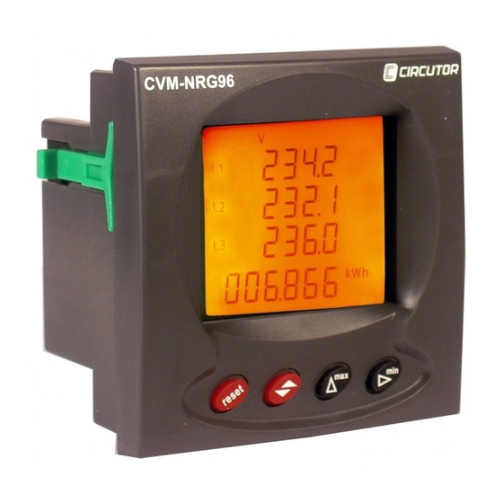
CVM-NRG96 General features The CVM-NRG 96 panel analyzer is a programmable measuring instrument; it offers a series of options for using it, which may be selected from configuration menus on the instrument itself. Before starting the analyzer carefully read sections: power supply, connection and setting and select the most suitable form of operation in order to obtain the required data. - Page 5 CVM-NRG96 The CVM-NRG 96 allows the display of all electrical parameters shown above, using the back-lit LCD display, showing 4 instant electrical parameters, maximum or minimum on each page jump. Other features: Small sized instrument (96x96x50). Measurement in true effective value.
-
Page 6: Installation And Start-Up
CVM-NRG96 Installation and start-up This manual contains information and warnings that must be followed by the user to ensure the safe operation of the equipment and to maintain it in a safe condition. The analyzer must not be switched on until it is finally attached to the electrical board. -
Page 7: Maximum Voltage In The Measurement Circuit
CVM-NRG96 Maximum voltage in the measurement circuit: - Voltage 300 V AC. phase-neutral 520 V AC. phase-phase - Frequency 45…65 Hz C. Maximum admissible current: - Current External transformers In /5A. D. Transistor features(output): - NPN Type Opto-isolated Transistor /Open Collector - Maximum operating voltage: 24 V.DC. - Page 8 CVM-NRG96 Terminal list No. Terminal description Power supply voltage input Power supply voltage input Transistor output RL1 Transistor output RL2 RS-485 ( + ) RS-485 ( - ) RS-485 ( GND ) Measurement VL1 Measurement VL2 Measurement VL3 Neutral measurement Current input AL1 –...
-
Page 9: Connection Diagrams
CVM-NRG96 Connection diagrams Three phase system measurement with 4 wire connection (Low Voltage) and three external current transformers. Power supply AC. // Version Plus DC. Power supply “Plus” Terminal Description + V DC. - V DC. Mn_cvm-nrg_03.doc... - Page 10 CVM-NRG96 Three phase system measurement with 3 wire connection (Low Voltage) and three external current transformers. Power supply AC. // Version Plus DC. Mn_cvm-nrg_03.doc...
- Page 11 CVM-NRG96 C. Three phase system measurement with 3 wire connection using 2 transformers and three external current transformers. Power supply AC. // Version Plus DC. Mn_cvm-nrg_03.doc...
- Page 12 CVM-NRG96 D. Three phase system measurement with 3 wire connection using 2 voltage transformers and two external current transformers. Power supply AC. // Version Plus DC. Mn_cvm-nrg_03.doc...
-
Page 13: Operation
CVM-NRG96 Operation Generic functions of the front keypad: Key Reset: Starting the equipment. Deletion of Maximum and Minimum values. This is equivalent to starting the equipment in the absence of voltage. Key Display: Displaying all variables by repeated presses. Function key in set-up menu: pressing the Display key moves forward through different screens, both on the configuration menu and the communications menu. -
Page 14: Simple Or Compound Voltages
CVM-NRG96 Configuration Menu TheCVM-NRG96 analyzer has two configuration menus: MEASUREMENT SETUP: from this menu, the user can set the measurement parameters and the analyzer's different display options. Measurement Setup Status (locked or unlocked) Simple or compound voltages Transformation ratios Power Demand Meter Setting... - Page 15 CVM-NRG96 Setting MEASUREMENT SETUP The parameters for the CVM-NRG 96 and all its functions are displayed and changed from this menu (according to type); it may start the eight energy meters and return maximum demand to zero (Pd), maximums and minimums recorded.
- Page 16 CVM-NRG96 Simples or Compound Voltages Simple Voltages Compound Voltages U1 2 U2 3 U3 1 To select one of the two display options, just press the MAX key and the two options will alternate. Once the required option is selected, press the key to enter the data and access the next setting step moving on to the next setting step.
- Page 17 CVM-NRG96 Transformer Voltage Secondary The display shows “set Uolt Sec” followed by three digits; these allow the setting of the transformer voltage secondary. Se t Uo l t Se c 0 0 1 To write or change the value of the transformer secondary value repeatedly press the MAX key increasing the value of the digit which is flashing at the time.
- Page 18 CVM-NRG96 Setting the Power Demand Meter Magnitude to Integrate The display shows “set pd Code” followed by two digits which identify the code or variable to be integrated as Maximum Demand. None Three phase active power kW III Three phase apparent power kV·A III...
- Page 19 CVM-NRG96 Deletion of maximum Demand The display shows “Clr pd no”. Cl r Cl r Ye s To select one of the two display options, just press the MAX key and the two options will alternate. Once the required option is selected, press the key to enter the data and access the following setting step.
- Page 20 CVM-NRG96 Preferred Magnitude of Energy The display shows ”set def pa9e Ener” and the Active Energy symbol (kWh) flashes. d EF PA9 E En e r By repeatedly pressing the MAX key the required energy magnitude is selected. This may be:...
-
Page 21: Deletion Of Energy Meters
CVM-NRG96 Backlight permanently on 01 … 60 Backlight on from 1 to 60 seconds. These values(t), refer to the time from the last time the equipment was used via the keypad. Deletion of Energy meters. Deletion of the eight Energy meters The display shows ”Clr ener no”. - Page 22 Digital output for the transistor. The CVM-NRG96's digital output may set: Pulse per n kW.h or kvar.h (Energy): the value for the energy consumed or generated may be set to generate a pulse.
- Page 23 CVM-NRG96 Once the energy code has been selected and entered using the key the watts per pulse must be entered or as a default kilowatts per pulse. Ou t Pu l s r a t e 0 0 . 0 0 0 000.500...
- Page 24 CVM-NRG96 Magnitude Phase Symbol L1 Code Simple Voltage Current Active Power kW 3 Reactive Power L/C KvarL/C 3 Power Factor PF 3 % THD V THD V3 % THD A THD A3 Magnitude Symbol Code Simple Voltages V1 / V2 / V3...
- Page 25 CVM-NRG96 Once the Alarm Condition code has been selected and the data entered using the the maximum value, minimum value and the delay (hysteresis) for the alarm condition must be entered. Ou t Ou t Ou t d e l a 0 0 0 .
- Page 26 Setting COMMUNICATION SETUP *(Only for models with communication) One or more CVM-NRG96 instruments may be connected to a computer or PLC in order to automize a production process or an energy control system. As well as the usual operation of each instrument, this system may centralize data at one single point;...
- Page 27 CVM-NRG96 Setting the communication parameters Default settings (factory settings) The display shows ”set Cdef no” s e t Se t Cd e f Cd e f y e s To select one of the two display options, just press the MAX key and the two options will alternate.
- Page 28 CVM-NRG96 To write or change the number of the peripheral repeatedly press the MAX key increasing the value of the digit which is flashing at the time. When the required value is on the screen, move on to the following digit by pressing MIN, to allow the remaining values to be changed.
- Page 29 CVM-NRG96 Once the required option is selected, press the key to enter the data and access the following setting step. Data Bits The display shows ”set data bits 8” d a t a b i t s This menu option is solely for information, because data bits cannot be changed.
- Page 30 CVM-NRG96 Protection of measurement SETUP The display shows “set UP unlo” s e t Se t u n l o L o c This menu option aims to protect the data set in the Measurement Setup. As a default the equipment does NOT protect data with the “unlo”, option and by...
- Page 31 CVM-NRG96 MODBUS Protocol © The CVM-NRG96 power analyzers communicate by using MODBUS© protocol, described below: In the MODBUS protocol the RTU (Remote terminal Unit) mode is used; each 8-bit byte in a message contains two 4-bits hexadecimal characters. The format for each byte in RTU mode...
-
Page 32: Modbus Memory Map
CVM-NRG96 MODBUS memory map © MODBUS VARIABLES Magnitude Symbol Instant Maximum Minimum Unit Voltage Phase V L1 V x10 00-01 60-61 C0-C1 Current A L1 02-03 62-63 C2-C3 Active Power kW L1 04-05 64-65 C4-C5 Reactive Power Kvar L1 06-07... - Page 33 CVM-NRG96 MODBUS VARIABLES Minimu Magnitude Symbol Instant Maximum Unit Active Energy w·h kW·h III 3C-3D 9C-CD FC-FD Inductive Reactive Energy kvarL·h III w·h 3E-3F 9E-9F FE-FF React. Energy Capacitive kvarC·h III w·h 40-41 A0-A1 100-101 Apparent Energy kVA·h III w·h...
- Page 34 CVM-NRG96 Example of a MODBUS© question QUESTION 0A 04 00 00 00 0A 71 76 Peripheral number, 10 in decimal Reading function Record at which the reading is to start 00 00 Number of recording to be read: 10 in decimal...
- Page 35 The composition of the RS-485 cabling must be carried out with a meshed screen cable (minimum 3 wire) with a maximum distance of 1,200 metres between the CVM-NRG96 and the master unit. This Bus may connect a maximum of 32 CVM-NRG96 analyzers.
- Page 36 CVM-NRG96 FAQ’s The CVM-NRG96 analyzer, once cabled and connected is seen to give a correct voltage and current reading, but shows negative values for active power (generation). This is an error with the cabling for the current transformer secondaries; the direction of the transformer current has to be respected as shown in the connection diagram.
- Page 37 Ensure that the equipment's communication parameters have been correctly set as well as the peripheral number (0 to FF). The CVM-NRG96 analyzer is connected to the Power Studio System and it does not communicate with the PC. Ensure that the analyzer has been set with a Bus speed of 19,200 bauds.
- Page 38 CVM-NRG96 Technical assistance: CIRCUTOR, SA Vial Sant Jordi, s/n 08232 Viladecavalls After sales department BARCELONA Vial Sant Jordi, s/n SPAIN 08232 Viladecavalls Tel. +34 93.745.29.00 BARCELONA Fax. +34 93.745.29.14 SPAIN web: http://www.circutor.com e-mail: medida@circutor.es e-mail: medida@circutor.es Mn_cvm-nrg_03.doc...
Need help?
Do you have a question about the CVM-NRG96 and is the answer not in the manual?
Questions and answers