Advertisement
Quick Links
Advertisement

Related Manuals for BHI NEDSP1061-PCB


Summary of Contents for BHI NEDSP1061-PCB
- Page 1 NEDSP1061-PCB Noise Eliminating Modules Installation and perating anual bhi ltd PO Box 318 Burgess Hill West Sussex RH15 9NR tel: +44 (0)845 217 9926 fax: +44 (0)845 217 9936 sales@bhi-ltd.com www.bhi-ltd.com 1061-108D Page 24 Page 1 Issue C...
- Page 2 Furthermore, bhi Ltd. reserves the right to revise this publication and to make changes from time to time in the content hereof without obligation of bhi Ltd. to notify any person of such revision or changes. Page 2...
-
Page 3: Table Of Contents
Notes: ontents Introduction 1.1 NEDSP1061 features 1.2 Limitations 1.3 Module connection and mounting 1.4 DSP noise cancellation Module description 2.1 Block diagram 2.2 Module layout 2.3 Pin functions 2.4 Controls 2.5 Electrical characteristics Installation Functions 4.1 Noise reduction levels 4.2 Pre-setting different DSP levels 4.3 Remote setting of DSP level 4.4 Noise cancellation on/off Application notes... -
Page 4: Limitations
Notes: 1. Introduction The NEDSP1061 is a modular solution to noise reduction. It incorporates DSP technology to provide up to 35dB of noise cancellation. 1.1 NEDSP1061 module features: Fully adaptive to changing noise environments Input and output level controls Virtually no distortion to speech signal Up to 35dB of noise cancellation 8 levels of noise reduction Noise cancellation can be preset or remotely set... - Page 5 Index 1.3 Module connection and mounting Application Notes 16 Audio bypass 19 Connections to the module are made by a row of 10 Audio input. 9 Audio out 9 pads at the right hand side of the PCB. These pads are on a 2.54mm (0.1”) pitch, which allows the use of standard pin headers, PCB connectors and direct wiring.
-
Page 6: Dsp Noise Cancellation
1.4 DSP Noise cancellation. 5.3 Driving a low impedance load. The bhi DSP processes the incoming signal and then If the target system loads the output of the DSP module differentiates the speech from the noise. The unwanted it may necessary to buffer the output. This can be noise and interference is then attenuated to leave only achieved with a single op amp. -
Page 7: Module Description 2.1 Block Diagram
The module can be controlled with a microcontroller. As 2. Module description the DSP employs internal pull ups, it is not necessary to drive the microcontroller port pins high, they can be 2.1 Block diagram. placed in a high impedance state. The NESDP1061 module has the facility to be preset, or adjusted during operation. -
Page 8: Module Layout
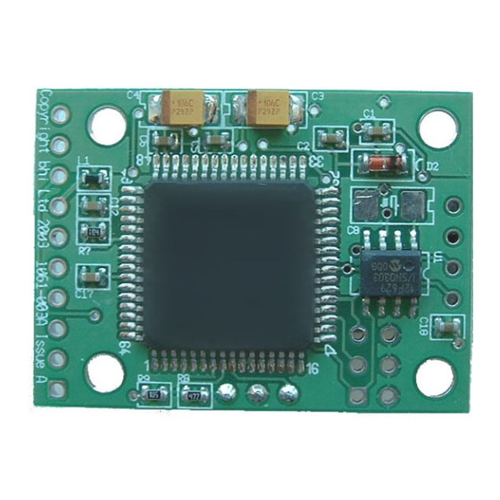
5.2 Remote adjustment of noise cancellation 2.2 Module Layout. level. The following diagram shows the layout of the This page illustrates various options for altering the DSP NEDSP1061 module. level remotely, during operation. Output Input level level 0V 7 NEDSP 1061 N2 3 Do not Connect... -
Page 9: Pin Functions
2.3 Pin functions. pplication Notes. The basic operation of the NEDSP pins are described below. More detailed descriptions can be found later in 5.1 Noise cancellation On/Off indication. this manual. Pins 1-3 DSP filter level set. These pins allow remote setting of the noise cancellation level. -
Page 10: Controls
2.4 Controls. The audio level control potentiometers P1 (Audio out), and P2 (Audio in) provide adjustment to the audio levels entering and leaving the module. P1 is factory set near to maximum. To set the input level correctly, adjust P2 until the overload led D1 (next to P2) illuminates, then back off the potentiometer approximately a 1/4 of a turn. -
Page 11: Installation
3. Installation The NEDSP1061 module is inserted into the path of noisy audio. Using the input and output level controls allows the unit to appear transparent to the audio signal. Audio in Audio out Pre amp NEDSP1061 Power amp Table 4. Preset DSP levels using on board jumpers. Microphone 4.3 Remote setting of DSP filter level. -
Page 12: Functions 4.1 Noise Reduction Levels
The NEDSP1061 requires a signal of 50mV rms or 4. Functions greater for optimum performance. Signals lower than this may be used but the noise cancellation performance will 4.1 Noise reduction levels. degrade, as the signal levels drops. If the unit is used with low level microphones, the signal will need amplifying 8 levels of noise reduction are available.
Need help?
Do you have a question about the NEDSP1061-PCB and is the answer not in the manual?
Questions and answers