Advertisement
Quick Links
SERVICE MANUAL
SAFETY-RELATED COMPONENT WARNING !!
COMPONENTS IDENTIFIED BY MARK ! OR DOTTED LINE
WITH MARK ! ON THE SCHEMATIC DIAGRAMS AND IN
THE PARTS LIST ARE CRITICAL TO SAFE OPERATION.
REPLACE THESE COMPONENTS WITH SONY PARTS
WHOSE PART NUMBERS APPEAR AS SHOWN IN THIS
MANUAL OR IN SUPPLEMENTS PUBLISHED BY SONY.
MICROFILM
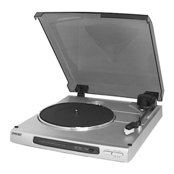
PS-J10
Canadian Model
AEP Model
Photo: SILVER
SPECIFICATIONS
ATTENTION AU COMPOSANT AYANT RAPPORT
À LA SÉCURITÉ!!
LES COMPOSANTS IDENTIFIÉS PAR UNE MARQUE ! SUR
LES DIAGRAMMES SCHÉMATIQUES ET LA LISTE DES
PIÈCES SONT CRITIQUES POUR LA SÉCURITÉ DE
FONCTIONNEMENT. NE REMPLACER CES COMPOSANTS
QUE PAR DES PIÈCES SONY DONT LES NUMÉROS
SONT DONNÉS DANS CE MANUEL OU DANS LES
SUPPLÉMENTS PUBLIÉS PAR SONY.
STEREO TURNTABLE SYSTEM
US Model
UK Model
E Model
SECTION 1
This section is extracted from
instruction manual.
GENERAL
– 2 –
Advertisement

Related Manuals for Sony PS-J10


Summary of Contents for Sony PS-J10
-
Page 1: Section 1 General
REPLACE THESE COMPONENTS WITH SONY PARTS FONCTIONNEMENT. NE REMPLACER CES COMPOSANTS WHOSE PART NUMBERS APPEAR AS SHOWN IN THIS QUE PAR DES PIÈCES SONY DONT LES NUMÉROS MANUAL OR IN SUPPLEMENTS PUBLISHED BY SONY. SONT DONNÉS DANS CE MANUEL OU DANS LES SUPPLÉMENTS PUBLIÉS PAR SONY. - Page 2 PS-J10 SECTION 2 DIAGRAMS 2-1. PRINTED WIRING BOARDS • Semiconductor Location Ref. No. Location D101 D102 D103 D104 D105 IC301 Q301 • Semiconductor Lead Layouts Note: • X : parts extracted from the component side. • b : Pattern from the side which enables seeing.
-
Page 3: Speed Adjustment
PS-J10 Note: • All capacitors are in µF unless otherwise noted. pF: µµF 50 WV or less are not indicated except for electrolytics and tantalums. • All resistors are in Ω and W or less unless otherwise specified. Note: Note: The components identified Les composants identifiés par... -
Page 4: Section 3 Exploded Views
SECTION 3 EXPLODED VIEWS NOTE: The components identified by • The mechanical parts with no reference number in • -XX, -X mean standardized parts, so they may have mark ! or dotted line with mark the exploded views are not supplied. some difference from the original one. -
Page 5: Section 4 Electrical Parts List
SECTION 4 POWER ELECTRICAL PARTS LIST Note: • Due to standardization, replacements in the parts list • RESISTORS The components identified by All resistors are in ohms may be different from the parts specified in the mark ! or dotted line with mark METAL: Metal-film resistor diagrams or the components used on the set. -
Page 6: Accessories And Packing Materials
PS-J10 POWER SPEED Ref. No. Part No. Description Remark < VARIABLE RESISTOR > 1-241-760-11 RES, ADJ, CARBON 470 1-241-760-11 RES, ADJ, CARBON 470 ************************************************************** 1-654-921-11 SPEED BOARD *********** S902 1-762-224-11 SWITCH, PUSH (SPEED) (1 KEY) ************************************************************** MISCELLANEOUS ************* 1-575-651-11 CORD, POWER (AEP)