Table of Contents
Advertisement
INSTRUCTIONS
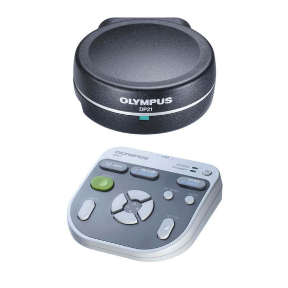
DP21
MICROSCOPE DIGITAL CAMERA
This instruction manual is for the Olympus Microscope Digital Camera Model DP21.
To ensure the safety, obtain optimum performance and familiarize yourself fully with the use of this
camera, we recommend that you study this manual thoroughly before operating the camera.
Retain this instruction manual in an easily accessible place near the work desk for future refer-
A X 7 9 3 1
ence.
Advertisement
Table of Contents
Troubleshooting

Related Manuals for Olympus DP21


Summary of Contents for Olympus DP21
- Page 1 DP21 MICROSCOPE DIGITAL CAMERA This instruction manual is for the Olympus Microscope Digital Camera Model DP21. To ensure the safety, obtain optimum performance and familiarize yourself fully with the use of this camera, we recommend that you study this manual thoroughly before operating the camera.
- Page 2 Refer to your local Olympus distributor in EU for return and/or collection systems available in your country. NOTE: This equipment has been tested and found to comply with the limits for a Class A digital device, pursuant to Part 15 of the FCC Rules.
-
Page 3: Table Of Contents
CONTENTS IMPORTANT (Common) 1-1 Safety Precautions ....................................1 1-2 Conformity of the System ................................2 1-3 Getting Ready ....................................... 3 1-4 Maintenance and Storage ................................3 1-5 Caution ........................................... 4 Standalone System (SAL) 5-66 2-1 Operating Precautions ................................5,6 2-2 System Chart ......................................... 7 2-3 Nomenclature..................................... - Page 4 3-2 System Chart ......................................68 3-3 Nomenclature......................................69 3-4 Installation ......................................70,71 3-5 DP2-TWAIN Software Installation ........................72-78 3-6 Image Recording Procedure Using DP21-TWAIN ................. 79 3-7 Displayed Windows of DP2-TWAIN ........................... 80 3-8 DP2-TWAIN Software Uninstallation ......................... 81 GENERAL (Common) 82-87 4-1 Warning Messages ..................................
-
Page 5: Important (Common)
2. Always use the AC adapter provided by Olympus. Using a similar but non-Olympus AC adapter does not only allow the camera to manifest its full performance but may also cause an equipment failure as well as a burn or fire hazard due to abnormal heating. Never use such an AC adapter. -
Page 6: Conformity Of The System
2. When the DP21 is connected to the rear port of the U-DPT or U-MPH, the peripheral part of the recorded image may be deteriorated due to the optical performance of the U-DPT or U-MPH. -
Page 7: Getting Ready
3. Do not disassemble any part of the camera as this could result in malfunction or reduced performance. 4. When the system is not used, store it with the dust cover. Before storage, ensure that the main switches of the DP21’s control box and the microscope are set to OFF and that the lamp housing is cool enough. -
Page 8: Caution
Note on Disposal Be sure to observe your local regulations and rules when disposing of this product. Special care is required for the control box because it incorporates a lithium manganese coin battery (CR2032). If you have any doubt, please consult Olympus. -
Page 9: Standalone System (Sal)
· Ensure that the network and PC to which the DP21 is connected are free of computer viruses. · Should infection of a computer virus occur or be suspected, turn the control box of the DP21 OFF and unplug its power cord. - Page 10 Battery Life The DP21’s control box incorporates a lithium ion coin battery (CR2032) for backing up the calendar function. The service life of the battery is 1 to 6 years (it is widely variable because the battery power consumption is reduced during operation connecting the AC adapter to the control box).
-
Page 11: System Chart
Microscope Erected Microscope (Note 1) Certain microscopes are also applicable even when they are not mentioned above. Please consult Olympus for details. (Note 2) Image color setup matching the microscope is required for faithful color reproduction (see page 34 for details). -
Page 12: Nomenclature
2-3 Nomenclature 2-3-1 Hardware controls Any equipment connected to the camera head should be an Olympus-designated product or a product in CAUTION compliance with the requirements of IEC60950 or CISPR22/24. If equipment other than these products is connected, Olympus cannot guarantee any performance of the camera. - Page 13 SAL System Control Box Front view Pilot LED Main switch USB ports LAN cable connector Rear view DC IN connector Display connector DVI-I/-D/-A RS232C connector Camera cable connector For connection of the USB ports control box (U-CBS, etc.) Stabilizer for Vertical Installation Stabilizer With 2 clamp screws...
-
Page 14: Menu / Info Display
2-3-2 MENU / INFO display MENU display INFO display (REC AUTO) No. of remaining image Exposure White balance (p. 33) (p. 23) time Exposure Image adjustment (p. 26) quality (p. 30) Scale setting (p. 35) ISO speed (p. 30) Metering Scale display area area (p. -
Page 15: Installation
If the save destination is set to a network location, the INFO display may sometimes not show the number of remaining image. 2-4 Installation This section pertains only to the installation of the DP21 microscope digital camera. For the installation of the combined microscope, camera adapter, etc., refer to their instruction manuals and install care- fully. -
Page 16: Installation
Installing the Control Box (Fig. 2) }The control box can be installed either horizontally or vertically. }Do not place a heavy object weighing over 10 kg or an object that would make the installation unstable on the control box. Horizontal installation Place the control box on the desktop so that its rubber feet contact the desktop surface. - Page 17 ² on the control box and secure the clamping screws on both sides of the connector. }Use a DVI cable matching the display as the display cable. The DP21 is compatible with either the DVI-I, D or A connector.
- Page 18 Disconnecting the AC Adapter Press the main switch @ of the control box to shut down the DP21 and confirm that the POWER LED ² is turned off completely (about 10 sec.) before unplugging the connector of the AC adapter.
- Page 19 USB port of the control box. The USB memory provided with the DP21 can also be used by inserting it into a USB port of the control box. }The ACCESS LED of the hand switch lights or blinks during data access (for saving the recorded image, etc.).
- Page 20 }It is not possible to install a special driver for the mouse or keyboard in the DP21. As a result, if a device requires a special driver, only the stan- dard functions of the device are available with the DP21.
-
Page 21: Basic Image Recording Procedure
SAL System 2-5 Basic Image Recording Procedure This section describes the basic operating procedure of the DP21 (from turning power ON to image recording) and the initial setting method. The information in this section is enough for mastering the basic method for recording still images and movies. -
Page 22: Turning Power On/Off
If the camera head is switched OFF during use If the camera head is turned OFF during use of the DP21 by accidentally setting the main switch to OFF or disconnecting the camera cable, the system detects that the camera head is not connected and displays an error message. If this happens, press the main switch of the control box to shut down the system. -
Page 23: Initial Setting
2. Set the language by following the wizard. 3. Also set the scale magnification (magnifications of the camera adapter and objective in use) in the same way. The DP21 restarts after comple- tion of the setting. }See page 54 for the language setting and page 35 for the scale magni- fication setting. -
Page 24: Selecting The Mode
REC MANUAL (manual-exposure recording) or PLAY (play- back) mode. }When the DP21 is turned ON and the REC AUTO or REC MANUAL mode is selected, the live image is displayed on the monitor screen. }The default setting is REC AUTO. From the next time, the system is started up in the mode selected when it was turned OFF the last time. -
Page 25: Viewing/Controlling The Menu Display
SAL System Viewing/Controlling the MENU Display 1. Press the MENU button @ to view or hide the MENU display alternately. For details on the MENU display items, see MENU display (p. 10). The MENU display is hidden with the default setting. 2. -
Page 26: Setting The Live Resolution
Setting the Live Resolution Default: 1600 x 1200 With the DP21, the resolution of the live image can be selected from three options of UXGA:1600 x 1200, SVGA:800 x 600 and SVGA (binning) 800 x 600. The characteristics of each resolution are as follows. -
Page 27: Recording Still Images
SAL System Recording Still Images ² 1. On the microscope, frame the image to be recorded and focus on it. To facilitate focusing, use the zoom display of the live image (p. 27) or display the focusing indicator (p. 37). 2. -
Page 28: Recording Movies
Recording Movies 1. On the microscope, frame the image to be recorded and focus on it. 2. While holding the SHIFT button @, press the EXPOSE button ² to start movie recording. 3. To stop movie recording, press the EXPOSE button ². The movie is saved in the USB memory. -
Page 29: Recording Function Setting/Operation (Rec)
Available Functions The hand switch of the DP21 incorporates the following functions. For details of each function, see the description in the applicable pages. -
Page 30: Exposure Adjustment
Exposure Adjustment REC AUTO mode The exposure time set by AE (Auto Exposure) can be corrected (by up to 2 EV in 1/3 EV steps). When the specimen is dark, +EV correction will extend the exposure time and give an over-exposure type effect. When it is bright, the -EV correc- tion will shorten the exposure time and give an under-exposure type effect. -
Page 31: Ae Lock Setting
SAL System AE Lock Setting REC AUTO mode only 1. Press the AE LOCK button @ to lock the current exposure time. The AE LOCK LED ² lights and the INFO display shows the locked exposure time. 2. Press the AE LOCK button @ again to cancel AE LOCK. When AE LOCK is set, the metering area, ISO speed and exposure ad- justment cannot be set. -
Page 32: Composite Button Operations
Composite Button Operations Pressing two buttons makes it possible to perform a quick setting as shown in the following table (¦: Possible / Impossible). To perform this, ensure that the MENU display is hidden, hold the “Held button” and press the “Switching button.”... -
Page 33: Operation Using The Menu Display
SAL System 2-6-2 Operation using the MENU display This section describes the operation method of the functions that are available in the MENU display on the monitor screen. This section pertains to the recording operation (in the REC AUTO/REC MANUAL modes). See page 21 for the basic operations and flow of the MENU display. -
Page 34: Image Quality Mode Setting
Image Quality Mode Setting Default: HQ }Select the quality of the recorded image. Image quality The image quality improves as the setting is advanced from “SQ-H” -- > “SQ-L” -- > “HQ” -- > “SHQ” -- > “TIFF.” Image quality mode Compression rate Save format Recording pixels... -
Page 35: Save Folder Setting
SAL System Save Folder Setting Default: AUTO When more than one DP21 unit records and saves images into the same Setting the save folder ² folder in a network PC, etc. at the same timing, an error about the impos- sibility of saving the recorded images may occur. - Page 36 Specifying the save folder by the address The save destination can be specified by entering the folder address. In addition, a pull-down menu is also available listing the recently-specified addresses (up to 10 addresses) so that the user can also select the desired address from them.
-
Page 37: White Balance (Wb) Mode Setting
}Pressing the OTWB button of the hand switch sets the OTWB mode automatically. Folder and File Names When an image is recorded, the DP21 automatically creates a folder in the image save destination and saves the image file in it. The folder and file names are created automatically as shown below. -
Page 38: Applied Operations
2-6-3 Applied operations This section describes the applied functions of the DP21. These functions make it possible to record observed images that match the user needs. Manual recording Manual recording makes it possible to record images by setting the exposure time manually as required. -
Page 39: Scale Display Setting
SAL System Scale Display Setting Default: OFF A scale can be displayed in the live image as well as in recorded images. The scale display setting can be saved and recalled later. Setting ³ ON/OFF ² 4-1 Displaying a Scale Objective power 1. - Page 40 Microscope setting Set the magnification information required for the scale display. }Before microscope setting, disconnect the USB memories (including the removable media devices such as HDD) from the hand switch and/or control box. They can be reconnected after completion of restarting (auto restart) after the setting. }When a control box (U-CBS, etc.) is connected, the setting methods are different from those described below.
-
Page 41: Default: Off
SAL System ³ Enter the objective power and its Memory No. (enter for each revolving nosepiece position). Scale Display Range Setting Default: LIVE & SNAP When the scale display is ON, it can be displayed in either way below. @To display the scale in both live and recorded images. ²... - Page 42 Focusing indicator }The focusing status of the incident light can be displayed for use as a reference for focusing. The focusing indicator is displayed as a bar as shown below at the bottom left of the monitor screen. It is switched automatically to the peak level display according to the specimen contrast.
-
Page 43: Default: Off
SAL System AE Area Display Setting Default: OFF }The average or spot metering area can be displayed on or hidden from the monitor screen. See page 26 for the metering area setting. Display AE area Hide Measurement Functions Distances and areas in the image can be measured. The measure- ments are possible by using the hand switch buttons or the mouse connected to the control box. -
Page 44: Measurement Functions
Measurement function list Icon Function Outline Remark (Restrictions) Page Distance of Measures the distance between 2 specified points. A total of 20 measurements are 2 points possible per image including the p. 41 functions in the range from “Dis- tance” to “XY Distances.” Poly-Line Measures the total sum of the distances between Up to 100 points can be specified... - Page 45 SAL System Distance of 2 Points This function measures the distance between two points specified by the user. 1. When is selected, pointer “ ” is displayed. The pointer can be moved Measurement target using the cursor buttons or the mouse. 2.
- Page 46 Distance between 2 Circle Centers This function draws two circles (each based on the three points specified by the user) and measures the distance between their centers. 1. When is selected, pointer “ ” is displayed. The pointer can be moved Measurement target using the cursor buttons or the mouse.
- Page 47 SAL System 4 Points Angle This function draws two lines on the image and measures the angle at the intersection of them. 1. When is selected, pointer “ ” is displayed. The pointer can be moved Measurement target using the cursor buttons or the mouse.
- Page 48 Polygon Area This function draws a polygon and measures its area. The polygon can have up to 100 corners. Measurement target 1. When is selected, pointer “ ” is displayed. The pointer can be moved using the cursor buttons or the mouse. The point is drawn on the specified position.
- Page 49 SAL System Distance of Parallel Lines This function draws a couple of parallel lines and measures the distance between them. 1. When is selected, pointer “ ” is displayed. The pointer can be moved Measurement target using the cursor buttons or the mouse.
- Page 50 Count This function draws markings and serial numbers on the specified positions. Up to 50 markings can be displayed simultaneously. }Even after this measurement is exited or another measurement function is performed, the markings are displayed in order of serial numbers unless they are erased. 1.
- Page 51 SAL System Text This function inputs a text in the image. The keyboard and mouse are required for the text input. 1. When is selected, pointer “ ” is displayed. The pointer can be moved Measurement target using the mouse. 2.
-
Page 52: Cross Lines Display
Erase All Files This function erases all of the measurements results displayed on the screen simultaneously. Select to erase all of the measurement results. Line/text color setup This function displays the measurement lines and texts (measured val- ues) in the color specified by the user. 1. -
Page 53: Playback Function Setting/Operation (Play)
SAL System 2-7 Playback Function Setting/Operation (PLAY) This section describes the method of image playback using the hand switch. The recorded images can be played back and viewed using the hand switch buttons. Selecting the Mode The MODE button @ can be used to select the REC AUTO (auto-expo- sure recording), REC MANUAL (manual-exposure recording) or PLAY (play- back) mode. -
Page 54: Selecting The Played Movie
Selecting the Played Movie When the image selected in “ Selecting the Played Image” is a movie, the display becomes as shown below. Press the SET/OK button to start playing the movie. To let the movie pause temporarily, press the MENU button. The playback can be resumed by pressing SET/OK. -
Page 55: Viewing The Index Display
SAL System Viewing the Index Display The index display shows the thumbnails of images in a folder. The played image can be selected from the thumbnails. 1. Press the cursor button @ during image playback to switch the image to the index display. 2. -
Page 56: Erasing An Image
}The measurement functions cannot be used when index images are displayed. }Measurement is not available with the following images. · Moving images · Images which have been edited with PC · Images recorded with a camera other than the DP21... -
Page 57: Menu Display Functions
SAL System 2-8 MENU Display Functions The MENU display has the functions for use in various settings. To execute a setting function, place the cursor on the applicable item and press the SET/OK button. If you are using the mouse, click it on the applicable item. Media Setup All of the files in the current save folder can be erased with this function. -
Page 58: Reset
}The save folder for the recorded image can be set as described in “Save Folder Setting” (p. 31). }When an image is recorded, the same folder as the save folder is set automatically as the play folder. Options This function changes the following settings for use in operation of the DP21. Maintenance Sleep setting 5-1 Language setting... -
Page 59: Maintenance Setting
SAL System 5-2 Sleep setting Default: OFF It is possible to turn off the display temporarily when the DP21 has not 1 min. been controlled for a certain period. 5 min. The display is turned on when any button is pressed. - Page 60 Monitor resolution setting Set the resolution value of the monitor in use. The resolution values that cannot be displayed on the connected monitor are not listed. The following resolution values can be selected. 1920 x 1200 WUXGA (image display area 1600 x 1200) 1680 x 1050 WSXGA+ (image display area 1280 x 960) 1280 x 854 WSXGA (image display area 1024 x 768) 1280 x 768 WXGA (image display area 1024 x 768)
- Page 61 · Playback of recorded images saved in a networked PC on the DP21. (Only the images recorded using the DP21 can be played back on it. Even when an image is recoded using the DP21, it may sometimes be unable to be played if it has been edited on the PC.)
- Page 62 This function copies the system information of the DP21 in the USB memory. It is usually not used. It is intended to be used when the user forwards the version information to Olympus in case of a trouble with the system, etc.
-
Page 63: Operation Using Mouse And Keyboard
Operation Using Mouse and Keyboard When the USB mouse is connected to the control box, the DP21 can be controlled using the mouse. However, the functions available with the dedicated buttons on the hand switch, such as OTWB cannot be controlled from the mouse. -
Page 64: Functions Interlocked With Microscope Operations
2-9 Functions Interlocked with Microscope Operations When the DP21 is connected to a microscope (BX43, BX53 or BX63) through a control box (U-CBS, etc.), the following functions interlocked with the microscope are available. Function Description Required units Auto scale When the objective in the revolving nosepiece of the microscope is ·... -
Page 65: Connection
· Remove the dust cover only from the areas used for the connections. CAUTION · Be sure to connect each connector to the module designated by Olympus. Olympus cannot guarantee any of the system performance if a non-designated module is used. -
Page 66: Connection
Connection of U-CBM OUT 1 to 4 connectors* (U-D7REA) U-CBM DP21-CB RS232C connector AC adapter for RS232C cable U-CBM RS232C connector * The OUT 1 to 4 connectors are universal type connectors. The U-D7REA can be connected to any of them. - Page 67 · Bank card · Floppy disk, etc. }Unless the U-D7RES is connected to the U-CBS, the U-HSEXP does not function. So be careful. }It cannot be recorded by the shutter switch. Use the DP21 hand switch to start/finish recording. (p.24)
-
Page 68: Operation
To use this function, It is necessary to input the magnifications of the objectives in use in the DP21 in advance. This input can be done by following the Microscope Setting Wizard that is displayed the first time the power is switched ON. If you have already started up the DP21, the objective magnifications can be input with the following procedure. - Page 69 SAL System 3. Input the camera adapter magnification. 4. Input the objective magnification and memory number for each revolving nosepiece position. @Input the magnification and memory number of the objective that is being engaged in the light path. ²Rotate the revolving nosepiece to engage the objective in the adjacent position in the light path. 3Input the magnifications and memory numbers of all of the objectives in the nosepiece positions by repeating steps @ and ²...
- Page 70 The shutter switch can be installed on the microscope by connecting the U-HSEXP to the U-CBS. This makes it possible to record images while manipulating the microscope. The shutter switch has the same function as the EXPOSE button of the DP21 hand switch. Pressing the shutter switch executes recording and saving of an image.
-
Page 71: Pc Connection System (Pc)
System Compatibility · To control the DP21, it is required to install a dedicated 1394 driver for the DP21. When this driver is installed, other 1394 devices cannot be used even when they are connected. The DP21-dedicated driver should be uninstalled before con- necting another 1394 device (the DP21 cannot be controlled after the DP21-dedicated driver is uninstalled). -
Page 72: System Chart
}If you use a SAL (Standalone) System, read from page 5. PC (Computer connection) System AX80/AX70 BX63/BX61 BX53/BX51 BX46/BX43/BX41 CX41/CX31 MX80/MX50/MX40 MX61L/MX61/MX51 Erected Microscope (Note 1) Microscopes that are not listed in the above may also be applicable. For details, please consult Olympus. -
Page 73: Nomenclature
PC System 3-3 Nomenclature Camera Head Main switch Pilot LED Camera cable connector C-mount thread Camera Cable Desktop PC cable 9-pin -- 6-pin, without lock Laptop PC cable 9-pin -- 4-pin, without lock Driver CD DP2-TWAIN... -
Page 74: Installation
Fig. 33 Field number 1X (FN 8.8) · If a C-mount TV adapter from other manufacturer than Olympus is used, the optical performance of the system may not be manifested fully. If the C-mount camera adapter or C-mount lens has a thread CAUTION length over 4.5 mm... - Page 75 Power supply to the camera The camera head of the DP21 has the main switch on it. Set this switch to ON when using the camera. The pilot LED on the camera head lights when power is supplied to the camera head.
-
Page 76: Dp2-Twain Software Installation
When the DP2-TWAIN is installed, the 1394 driver is also replaced with the dedicated driver for the CAUTION DP21. This makes it impossible to use other IEEE1394 devices. If you want to use an IEEE1394 device other than the DP21, see “DP-21 TWAIN Software Uninstallation (p. 81).”... - Page 77 8. Check [DP21] in the Device column. and the following window appears. When [DP21] has been checked, the dialogue box shown 6. Read the displayed Licensing Agreement, check “Yes, I below appears. Click on the [OK] button to close the box accept all the terms of the Licensing Agreement.”...
- Page 78 10. The [Select Additional Tasks] window appears. Check the 12. When [Windows Security] screen is displayed, click [Install]. task to be used and click on the [Next] button. 13. When the installation completes, the window below ap- pears. Then click on the [Finish] button. 11.
- Page 79 [OLYMPUS (R) MICROSCOPE 1394 DIGITAL CAMERA SYSTEM] has not been installed to 1394 connec- tor of PC connected to DP21. If DP21 is not operable, please confirm 1394 connector prior to using, and connect DP21 again to 1394 connector to which [OLYMPUS (R) MICRO- SCOPE 1394 DIGITAL CAMERA SYSTEM] has been installed.
- Page 80 4. Click on the [Start] button and then click on [Run]. 5. Select “setup.exe” in the CD-ROM drive folder and click on the [OK] button. 6. Wait a while until the preparation for installation completes and the following window appears. 9. Check [DP21] in the Device column.
- Page 81 PC System When [DP21] has been checked, the dialogue box shown 12. The [Start Copying Files] window appears. below appears. Click on the [OK] button to close the box Click on the [Next] button. and click on the [Next] button shown above.
- Page 82 MICROSCOPE 1394 DIGITAL CAMERA SYSTEM” is installed for the PC’s 1394 connector to which the DP21 is connected. If the DP21 does not run, check the connected 1394 connector and make sure to connect the DP21 is to a connector for which “OLYMPUS MICROSCOPE 1394 DIGITAL CAMERA SYSTEM”...
-
Page 83: Image Recording Procedure Using Dp21-Twain
PC System 3-6 Image Recording Procedure Using DP21-TWAIN (Notes) For detailed operating procedures, refer to the instruction manual for the DP2-TRAIN. *1. For zooming, scrolling and image saving, refer to the manual for the TWAIN-compatible application. Brightfield Observation Flow Set up the microscope. -
Page 84: Displayed Windows Of Dp2-Twain
3-7 Displayed Windows of DP2-TWAIN Image Record Window }This window is displayed at the startup and used to record still images and movies. For details, refer to the DP2-TWAIN instruction manual. Image capturing Exposure mode setting Exposure time setting (Only when the exposure mode is Manual) AE lock Metering area selection... -
Page 85: Dp2-Twain Software Uninstallation
Even when OLYMPUS DP2-TWAIN is uninstalled, the 1394 driver is not uninstalled, which means that an IEEE1394 device other than the DP21 is still unusable. If you want to use an IEEE1394 device other than the DP21, open the Device Manager and... -
Page 86: General (Common)
GENERAL (Common) 4-1 Warning Messages The DP21 sometimes displays a message according to the camera status and operation. Type Content Example Notification Notification of information on the camera status, end of processing, etc. The message disappears in 3 sec- onds after it is displayed or when any button is pressed. -
Page 87: Specifications
Common 4-2 Specifications Common Item Specifications Size 1/1.8-inch color CCD Effective pixels 2.01 megapixels (total pixels 2.11 megapixels) Scanning Progressive scanning Image pickup method device Color filters RGB primary color on-chip filters Recording area 7.04(H) x 5.28(V) mm, diagonal length 8.8 mm Max. -
Page 88: Specifications
Item Specifications Recording media USB memories, networked PC Image display speed Live image: 15 fps (Displayed pixels 1600 x 1200), (Frame rate) 27 fps (Displayed pixels 800 x 600) Display magnifications: 1x, 2x (electronic zoom), 4x (electronic zoom) Played image magnification: Index display, 1x, 2x, 4x Input/output connectors DC input: Main power supply... -
Page 89: Troubleshooting Guide
Under certain conditions, the performance of the camera may be adversely affected by factors other than defects. If problems occur, please review the following list and take remedial action as needed. If you cannot solve the problem after checking the entire list, please contact Olympus for assistance. Problem... - Page 90 The screen color setup is incorrect. Correct to the optimum color setup. h) Another 1394 device cannot be The DP21-dedicated driver is installed. When the DP21 is connected to a PC, used simultaneously. other 1394 devices cannot be used on the same PC.
- Page 91 Functions interlocked with micro- Cables are connected improperly. Connect the cables of the microscope, scope operations do not work. control box for coded units and DP21 61,62 correctly. The control box for coded units is not Set the main switches of the control recognized.
-
Page 92: Index
4-4 Index Numerics ERASE ................p.8,52 LAN connection ............p.16 1394 cable ................p.9 EXPOSE ................p.8,27 Language setting ........p.17,19,54 3 Points Angle measurement ....p.41 Exposure adjustment ......p.10,25,26 Laptop PC 4 Points Angle measurement ....p.43 Exposure time ....... p.10, 1 1,34,79,80,83 Connection method ...... -
Page 93: Troubleshooting Guide
Common Perpendiculars measurement ....p.43 Text ....................p.46 PLAY mode ............... p.49 Thumbnails ............... p.51,59 Polygon Area measurement ...... p.44 TIFF ..................... p.30 Power supply ............p.18,71 Troubleshooting Power ON/OFF ............p.18 -- > Troubleshooting guide ......p.85 REC AUTO mode ........p.10, 1 7,20 USB ................ -
Page 94: Proper Selection Of The Power Supply Cord
If no power supply cord is provided, please select the proper power supply cord for the equipment by referring to “ Specifications ” and “ Certified Cord ” below: CAUTION: In case you use a non-approved power supply cord for Olympus products, Olympus can no longer warrant the electrical safety of the equipment. - Page 95 Common Table 2 HAR Flexible Cord APPROVAL ORGANIZATIONS AND CORDAGE HARMONIZATION MARKING METHODS Alternative Marking Utilizing Printed or Embossed Harmoniza- Black-Red-Yellow Thread (Length tion Marking (May be located on Approval Organization of color section in mm) jacket or insulation of internal wir- ing) Black Yellow...
- Page 96 MEMO...
- Page 98 Shinjuku Monolith, 3-1, Nishi Shinjuku 2-chome, Shinjuku-ku, Tokyo, Japan Wendenstrasse 14-18, 20097 Hamburg, Germany 3500 Corporate Parkway, Center Valley, Pennsylvania 18034-0610, U.S.A. 491B River Valley Road, #12-01/04 Valley Point Office Tower, Singapore 248373 31 Gilby Road, Mount Waverley, VIC., 3149, Melbourne, Australia 5301 Blue Lagoon Drive, Suite 290 Miami, FL 33126, U.S.A.
Need help?
Do you have a question about the DP21 and is the answer not in the manual?
Questions and answers