Table of Contents
Advertisement
Advertisement
Table of Contents

Summary of Contents for Reichert PHOROPTOR
- Page 1 REICHERT PHOROPTOR ® ® Refracting Instrument User’s Guide...
- Page 2 The information contained in this document was accurate at time of publication. Specifications subject to change without notice. Reichert Technologies reserves the right to make changes in the product described in this manual without notice and without incorporat- ing those changes in any products already sold.
-
Page 3: Table Of Contents
Unpacking Instructions ..................8 Accessories ....................8 Parts Identification ................... 9 Illuminated Phoroptor (Catalog # 11636, 11367, 11656, 11657) ....11 Setup ......................12 Attaching the Phoroptor to the Stand ............. 12 Connecting the Power (For Illuminated Phoroptors Only) ...... 12 Attaching the Face Shields .............. -
Page 4: Warnings And Cautions
Warnings and Cautions Reichert Technologies (Reichert) is not responsible for the safety and reliability of this instrument when: • Assembly, disassembly, repair, or modification is made by unauthorized dealers or persons. • Instrument is not used in accordance with this Service Manual. - Page 5 PERFORMANCE BY LEAVING BEHIND FINGERPRINTS OR OILS ON THE LENSES. CAUTION: DO NOT IMMERSE THE PHOROPTOR IN FLUIDS OR DAMAGE TO THE UNIT MAY OCCUR. CAUTION: ENSURE THAT THE VOLTAGE APPLIED TO THE UNIT IS THE SAME AS THE VOLTAGE THAT IS INDICATED ON THE DATA PLATE OR DAMAGE TO THE UNIT MAY OCCUR.
-
Page 6: Symbol Information
Symbol Information The following symbols appear on the instrument. CAUTION - Consult accompanying documents. Type B Product Classification Conformity with mandatory European safety requirements Date of Manufacture Waste of Electrical and Electronic Equipment Catalog Number. Serial Number. Accompanying Documents must be consulted Fragile Contents in Shipping Container - handle with care. -
Page 7: Introduction
All parts of this ME system are suitable for use within the patient environment. Please retain this guide for future reference and to share with other users. For additional copies of this manual or questions related to the Phoroptor, contact your local authorized Reichert dealer or contact our Customer Service department directly at:... -
Page 8: Instrument Setup
• Transformer, 5V DC (P/N 11636-401 or P/N 11636-405, for Illuminated Phoroptors only.) Note: If any of the above accessories or parts are missing, immediately contact Reichert so that the missing accessories or parts can be shipped. For more accessories or to order any of these accessories, contact your authorized Reichert dealer. -
Page 9: Parts Identification
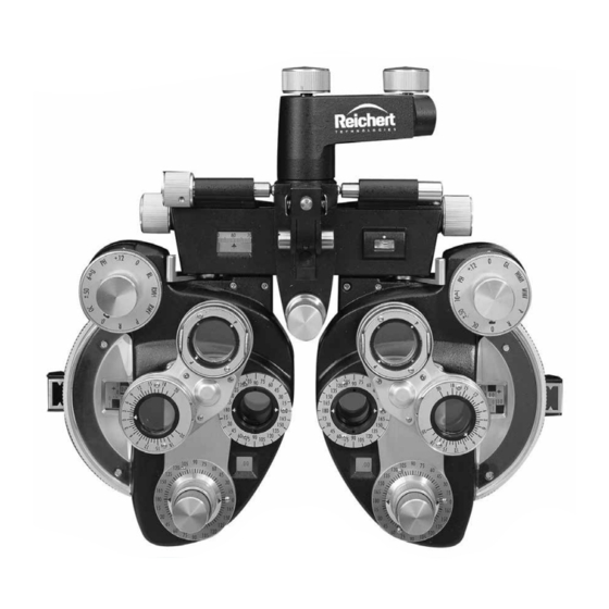
Instrument Setup (continued) Parts Identification Phoroptor (Front) 1. Rotation Adjustment Knob 14. Cross Cylinder Unit 2. Mounting Bracket 15. Cylinder Power Scale 3. Tilt Clamp Knob 16. Cylinder Axis Reference Scale 4. Forehead Rest Knob 17. Cylinder Axis Indicators 5. Spirit Level 18. - Page 10 Instrument Setup (continued) Parts Identification (continued) Phoroptor (Back) 1. Forehead Rest 2. Spring Clip Note: The configuration of the Reichert Phoroptor is a registered trademark in the United ® States & Canada. 11625-101-Rev. L...
-
Page 11: Illuminated Phoroptor (Catalog # 11636, 11367, 11656, 11657)
The illumination option reduces eyestrain by lighting the most commonly used scales and dials. Lighting is provided by energy efficient, cool running LEDs (light emitting diodes) that require no maintenance. Operators simply plug the Illuminated Phoroptor into the appropriate power receptacle to turn the lighting on. All other instrument functions remain unchanged. -
Page 12: Setup
PORTING ARM AND CAUSE SERIOUS INJURY. 1. Place the Phoroptor on the instrument stand arm by sliding the Mounting Bracket over the end of the arm until the threaded hole of the stand arm lines up with the slotted hole in the bottom of the Mounting Bracket. -
Page 13: Attaching The Face Shields
1. Each Face Shield is held in place by a Spring Clip. Attach by sliding the edge of the Face Shield under the clip matching the position of the shield aperture to the main aperture of the Phoroptor. Refer to Figure SU-2. -
Page 14: Attaching Reading Rod
1. Insert the Reading Rod into the hinged Reading Rod Holder and tighten the Reading Rod Clamp Screw. Note: The rod supplied with the Phoroptor is 28 inches (71 cm) in length to allow testing for multi- focal lenses. Note: The graduations are in inches, centimeters, and diopters. -
Page 15: Description Of Operation
The Phoroptor is made up of several sets of dials that control lenses inside the unit. Once the operator becomes familiar with the lenses and dials, operation of the Phoroptor will become quick and routine. -
Page 16: Instructions For Use
Depending upon whether the patient’s eyeglasses are to be adjusted to center the lenses before his eyes or decentered vertically to compensate for the vertical imbalance of the eyes, the Phoroptor may or may not be tilted to center the patient’s eyes in the apertures. -
Page 17: Optical Corneal Aligning Device
7. With this as the standard, the posterior lens surface of the Phoroptor must be placed at a distance of 13.75 mm if the Phoroptor reading is to be directly applied to spectacle lens power. - Page 18 Note: First, assume the Corneal Aligning Device indicates an additional 4 mm; that the spectacle lenses are to be worn at 12 mm instead of 13.75 mm; and that the Phoroptor reading is +13.00 diopters. In this case, fitting distance of 12 mm is subtracted from the refracting distance of 17.75 mm (13.75 mm plus 4 mm), the result being 5.75 mm.
- Page 19 = the distance moved from the spectacle vertex distance P(e) = the corrected power required at the spectacle vertex distance The correction factor is the difference between the effective power and the Phoroptor power cf = P(e)-P . 11625-101-Rev. L...
-
Page 20: Taking Measurements
Instructions for Use (continued) Taking Measurements Distance Tests 1. All tests for distance (static retinoscopy, subjective, phorometry) are generally made with the Vergence Levers in the extreme outward position. Refer to Figure TM-1. 2. At this setting the lens systems are parallel. (For shorter test distances than 20 feet, compensa- tory adjustments may be made by moving the levers inward). -
Page 21: Near Tests
Instructions for Use (continued) Taking Measurements (continued) Near Tests 1. All tests for near (dynamic retinoscopy, amplitude of accommodation, dynamic cross cylinder, positive and negative relative accommodation, phorometry) are generally made with the Vergence Levers in the inward (converged) position. Refer to Figure TM-2. -
Page 22: Operation Of The Sphere Lens Dials
Instructions for Use (continued) Taking Measurements (continued) Operation of the Sphere Lens Dials 1. All sphere powers, plus and minus, can be introduced into the lens aperture in steps of 0.25D by rotation of a single lens dial, (+0.12D sphere in the Auxiliary Lens Knob can be used to refine the spherical correction to 1/8th D steps.) 2. - Page 23 Instructions for Use (continued) Taking Measurements (continued) Operation of the Sphere Lens Dials (continued) 6. The Strong Sphere Control introduces sphere power in 3.00D steps and can often be used as a time saver. Examples: • To obtain a power of +2.75D (starting from zero), the practitioner could add plus power in quarter diopter steps by rotating the Weak Sphere Dial downward until +2.75D shows on the sphere power scale.
-
Page 24: Cylinder Power And Axis
Instructions for Use (continued) Taking Measurements (continued) Cylinder Power and Axis 1. In the Cylinder Lens Dials, which are controlled by turning the Cylinder Power Knobs, the powers range from 0.00 to -6.00D for instruments contain- ing minus cylinders, and from 0.00 to +6.00D for instruments containing plus cylinders. -
Page 25: Auxiliary Lens Dial
Auxiliary Lens Dial 1. The Auxiliary Lens Dial is controlled by turning the Auxiliary Lens Knob. The Phoroptor provides a selection of 10 auxil- iary lenses plus two open apertures. Refer to Figure TM-7. 2. Beginning at “O” (open aperture) at the top... -
Page 26: Rotary Prisms
Instructions for Use (continued) Taking Measurements (continued) Rotary Prisms 1. Each Rotary Prism Unit (loupe) has a range of 20 . Finger Roll Knob 2. Paired, prisms give 40 in any base direction. 3. The scale is marked in broad divisions of one prism diopter ( ). -
Page 27: Cross Cylinders
Instructions for Use (continued) Taking Measurements (continued) Cross Cylinders 1. The standard cross cylinder cells supplied are Roll +0.25D. These cells are removable and +0.37D Knobs and +0.50D are available and may be substituted. 2. The power of the cross cylinder is engraved on the cell. -
Page 28: Jackson Cross Cylinder Tests
Jackson Cross Cylinder Tests One of the unique features of the Phoroptor is that the Cross Cylinder Unit (loupe) lenses are geared to- gether with the correcting cylinder test lenses so that when a change in axis is made in the latter, a cor- responding change will automatically occur in the axis of the cross cylinder lenses. -
Page 29: Power Check
Instructions for Use (continued) Jackson Cross Cylinder Tests (continued) Procedure (continued) Axis Check (continued) 4. The axis check test is performed in the usual manner with the cross cylinder lens flipped from position I to position II. Refer to Figures JC-2. a. - Page 30 Instructions for Use (continued) Jackson Cross Cylinder Tests (continued) Procedure (continued) Power Check (continued) 2. Since the cross cylinder is in the axis check posi- tion, the practitioner merely rotates the unit 45° clockwise to the detent for proper power check positioning.
-
Page 31: Cleaning & Maintenance
FOR CLEANING ONCE EVERY THREE YEARS. Cleaning Make it a habit to always keep your Phoroptor covered when it is not in use. The Dust Cover provided will aid in keeping lenses clean and keep dust from working inside the instrument and eventually con- taminating the lubricant. -
Page 32: Cleaning Procedure
4. Indirect illumination from a standard lamp bulb through the instrument apertures will help identify soiled lenses. Lenses may be cleaned with the Phoroptor in place on the instrument stand for easiest handling or the instrument may be removed and supported on a sturdy, padded table. -
Page 33: Lens Replacement
Cleaning & Maintenance (continued) Lens Replacement Replacing Lenses in Auxiliary Dial - Old Style Phoroptors Five lenses in each dial are cell mounted: the retinoscopic, polarizing, both Maddox rods, and fixed cross cylinder lenses are in individual cells permitting substitution of special lenses. Two washers and screws retain each cell. -
Page 34: Changing Cross Cylinder Lens Assembly
Cleaning & Maintenance (continued) Lens Replacement (continued) Changing Cross Cylinder Lens Assembly The cross cylinder is changed as a complete assembly. Follow the procedure below and refer to Figures MM-1, and MM-2. 1. Using a 0.060-6 Spline Screwdriver, remove the two spline screws. -
Page 35: Adjustments
Cleaning & Maintenance (continued) Adjustments Adjusting Tension of Hinged Reading Rod Holder The Reading Rod Holder is held in the stored position by a spring clip. The Rod Hinge contains two pins Clip which engage into the clip when moved to the vertical position. -
Page 36: Troubleshooting
Troubleshooting Due to the Phoroptor being enclosed and the mechanical nature of the unit, problems associated with the Phoroptor should be handled by trained Reichert personnel. Please contact Reichert customer service with the contact information located in the Introduction section of this manual, or on the back cover. -
Page 37: Specifications
Specifications Catalog Number Ultramatic RX Master Phoroptor: 11625, 11635 Illuminated Phoroptor: 11636, 11637, 11656, 11657 , 11676, 11677 Physical Dimensions Size: Weight, unpacked: 9.5 lbs. (4.3 Kg) Height: 11.56 in. (29.36 cm) Width: 12.75 in (32.38 cm) Depth: 3.90 in (9.91 cm) -
Page 38: Storage Conditions
Storage Conditions Always place the Dust Cover on the Phoroptor when not in use to ensure that dust and other contami- nants do not get inside the unit. Over time, the presence of dust and other contaminants inside the unit may affect operation of the Phoroptor. -
Page 39: Warranty
Reichert instruction manual; nor to a product that has been sold, serviced, installed or repaired other than by Reichert or by an authorized Reichert Ophthalmic Instrument Dealer. - Page 40 3362 Walden Ave Depew, NY 14043 Toll Free: 888-849-8955 Phone: 716-686-4500 Fax: 716-686-4555 Email: reichert.information@ametek.com www.reichert.com AMETEK GmbH Business Unit Reichert Carl-von-Linde-Strasse 42 85716 Unterschleissheim/Munich Germany Email: info.reichert-de@ametek.com Tel: +49 (89) 315 8911 0 Fax: +49 (89) 315 891 99 ISO-9001/13485 Registered 11625-101, Rev.
Need help?
Do you have a question about the PHOROPTOR and is the answer not in the manual?
Questions and answers