Otto Bock C2000 Instructions For Use Manual
Hide thumbs
Also See for C2000:
- Instructions for use manual (188 pages) ,
- Service instructions manual (124 pages) ,
- Instructions for use manual (76 pages)

Related Manuals for Otto Bock C2000


Summary of Contents for Otto Bock C2000
- Page 1 C2000 Instructions for use ....................
- Page 2 [ ] Seat height adjustment [ ] Back angle adjustment [ ] Light [ ] Direction indicator, right [ ] Direction indicator, left [ ] Horn [ ] Warning flasher [ ] Other: *See the section "Use" for more information. 2 | Ottobock C2000...
-
Page 3: Table Of Contents
Adjusting the armrests ......................... 7.3.5 Adjusting the footrest and calf pad ......................7.3.6 Adjusting the control panel position ....................... 7.3.7 Changing control unit parameters ....................................................... Circuit breaker ........................... Side panels ............................8.2.1 Removing/installing the side panels ....................... C2000 Ottobock | 3... - Page 4 ......................... 8.15.2 Attendant control ..........................8.15.3 Push-button module ..........................8.15.4 Special controls ..........................8.15.5 Adapter cable for Piko button ....................... 8.16 Additional options ..........................8.16.1 Control panel holder ..........................8.16.2 Belts/belt systems ..........................8.16.2.1 Adaptation ............................4 | Ottobock C2000...
- Page 5 11.3 Warranty ............................11.4 Service Life ............................11.5 Trademarks ............................Technical data ..............................Appendices ................................ 13.1 Threshold values for wheelchairs transportable by train ................13.2 Required Tools ........................... 13.3 Torque values of the screw connections ....................C2000 Ottobock | 5...
-
Page 6: Foreword
• C2000: For indoor and outdoor use C2000-H: For indoor and outdoor use; power seat height adjustment included as standard equipment • The wheelchair was designed especially for users who are able to move about independently with it: The wheelchair may only be used with the options listed in the product order form. -
Page 7: Indications
Modular design that allows the power wheelchair to be equipped with additional modules and installed equip ment in addition to the main components, such as special controls (see Page 53). • Serviceability due to easy, straightforward access to all components. C2000 Ottobock | 7... -
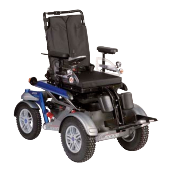
Page 8: Product Overview
Product description 3.2 Product Overview Backrest Drive wheel Rear lighting Footrest Luggage carrier Front lighting Charging receptacle Armrest (side panel) Caster wheel Control panel with joystick 8 | Ottobock C2000... -
Page 9: Safety
► If the service life is reached, the user or a responsible attendant should contact the qualified personnel who fitted the product or the manufacturer's servicing department (see inside rear cover or back page for address). Here the user can obtain information about known risks and the current options for refurbishing the product. C2000 Ottobock | 9... -
Page 10: Effects Of Electromagnetic Interference On The Product And On The User
The product has not been approved by the manufacturer for use as a seat in vehicles for transporting persons with reduced mobility European article number (EAN) Product reference number 10 | Ottobock C2000... -
Page 11: Warning Labels
► Deactivate the circuit breaker if the wheelchair is not used for more than 3 days. ► To deactivate the circuit breaker: see Page 19 Please observe the following if the power wheelchair is not used for more than 3 days: C2000 Ottobock | 11... -
Page 12: Preparation For Use
► Only use insulated tools to perform maintenance work on the batteries. ► Ensure correct polarity when you connect the battery cables. Connect the black cable to the negative terminal and the red cable to the positive terminal. 12 | Ottobock C2000... -
Page 13: Initial Operation
Risk of falling, tipping over or improper user posture due to incorrect settings ► Adjustments may only be carried out by qualified personnel instructed by the manufacturer. ► Check for safe function before delivering the product. C2000 Ottobock | 13... -
Page 14: Adjusting The Standard Seat
► Use only the original packaging for delivery of the product. 7.2.2 Adjusting the standard seat 7.2.2.1 Adjusting the Back Upholstery INFORMATION A well-adjusted backrest provides lasting comfort for the wheelchair user and reduces the risk of secondary dam age and pressure zones. 14 | Ottobock C2000... -
Page 15: Inserting Foam Elements
► Excessively tight adjustment of the belt system may lead to unnecessary pain or illness of the user. ► Adjusting the belt system too loosely can cause the user to slide into a dangerous position. In addition, the fastening snaps could open unintentionally if they slide against hard parts of clothing (e.g. buttons). C2000 Ottobock | 15... -
Page 16: Changing Control Unit Parameters
► After all adjusting/readjusting work authorised by the manufacturer, retighten the mounting screws/nuts firmly. Observe any torque settings which may be specified. 7.3.2 Adjusting the belt length Notes on correctly applying and adjusting the lap belt: see Page 22. Notes on correctly adjusting and applying the belts/belt systems: see Page 55. 16 | Ottobock C2000... -
Page 17: Adjusting The Back Angle
Adjusting the armrest to the forearm length 1) Loosen the 2 Allen head screws on the underside of the armrest. 2) Push the armrest to the front or back into the desired position. 3) Tighten the 2 Allen head screws. C2000 Ottobock | 17... -
Page 18: Adjusting The Footrest And Calf Pad
INFORMATION: If the control panel rail is too long it can be shortened. Please contact the qualified personnel who adjusted your product. 3) Tighten the 3 set screws on the bottom of the arm rest. 18 | Ottobock C2000... -
Page 19: Changing Control Unit Parameters
The installed armrests offer the user additional support for the forearms. 8.2.1 Removing/installing the side panels INFORMATION To remove the side panels with lighting: see Page 41. To make getting in from the side easier or for transportation, the side panels can be removed if needed. C2000 Ottobock | 19... -
Page 20: Footrest
The backrest provides pressure redistribution and support for the upper body. 8.4.1 Folding the backrest up/down The wheelchair may be delivered with the backrest folded down. It has to be folded up and secured prior to use. 20 | Ottobock C2000... -
Page 21: Getting In And Transferring
Getting into and out of the wheelchair can be done by the user individually in a way that suits him or her best. C2000 Ottobock | 21... -
Page 22: Lap Belt
If the lap belt is too loose, the user can shift/slide out to the front. • During the installation/adjustment, the lap belt is routed over parts of the seating system (e.g. over armrests or seat pads). This causes the lap belt to lose its retaining function. 22 | Ottobock C2000... -
Page 23: Use
→ It should be possible to slide two fingers com fortably between the strap and thigh. 2) Pull to check that it is secure. Opening the lap belt 1) Press the release button. 2) Open the belt buckle and lay the belt to the side. C2000 Ottobock | 23... -
Page 24: Control Unit
The control panel is used to switch the power wheelchair on and off, enter driving commands and display the cur rent status of certain functions and components. Front Joystick [On/off] button LCD screen [Mode] button [Warning flasher on/off] button [Horn] button [Direction indicator left/right – on/off] button [Lights on/off] button 24 | Ottobock C2000... -
Page 25: Buttons And Display Functions
The LCD screen is the communication interface between the user and the control unit. It indicates the selected speed level, the battery charge level and the status of power options, as well as warnings and faults. All display symbols are displayed while powering up. C2000 Ottobock | 25... - Page 26 If only 1 blinking segment is shown on the LCD screen (or all segments are off), the battery is in a low voltage state. Because further use will result in battery damage, the warning signal is also shown on the LCD screen. The battery must be charged immediately. 26 | Ottobock C2000...
-
Page 27: Driving Functions
Risk of falling out of the power wheelchair due to lack of restraint ► Always use the installed belt system when driving in public. ► Information about subsequent acquisition and mounting is provided by the qualified personnel that handed the product over to you. C2000 Ottobock | 27... - Page 28 ► The seat and backrest upholstery as well as padding fulfil the requirements for flame resistance according to ISO 8191-2 and DIN EN 1021-2. However, they may still ignite if fire is handled improperly or negligently. ► Keep away from all ignition sources, especially lit cigarettes. 28 | Ottobock C2000...
-
Page 29: Driving Notes
(wheelchair weight + user weight + payload) as well as the ground condi tions, exterior temperature, battery voltage and driving style of the user. In individual cases, the continuous climbing ability can be significantly lower than the value specified. C2000 Ottobock | 29... -
Page 30: Switching On And Off
Malfunctions such as an insufficient supply of power to the controls are recognised by the software, triggering an emergency stop or reducing the speed of the product. A warning signal will also sound. 30 | Ottobock C2000... -
Page 31: Selecting The Speed Levels
The user is able to drive the product out of a hazardous situation at any time. The product is fully functional again once the unit has cooled down sufficiently (this may take several minutes depending on the ambient temperature). The power wheelchair is controlled by moving the joystick: C2000 Ottobock | 31... -
Page 32: Range
2) Push the joystick all the way forward until a beep sounds. 3) Push the joystick all the way back until a beep sounds. 4) Release the joystick. → A long beep confirms that the driving function is enabled. 32 | Ottobock C2000... -
Page 33: Steering Lock
2) Push the [Warning Flasher On/Off] button (see Page 24). → The steering lock is deactivated. → All warning flasher lights stop flashing. 3) Move the joystick. The power wheelchair now drives in the chosen direction without the steering lock. C2000 Ottobock | 33... -
Page 34: Adjusting The Driving Characteristics
→ After switching the control unit on: The control unit recognises that the brake has been unlocked and deactivates the driving function. → A warning will appear on the control panel or LCD monitor when the joystick is deflected: Display Information Brake unlocked 34 | Ottobock C2000... -
Page 35: Batteries/Charging Process
After charging the batteries, the circuit breaker should be deactivated if the wheelchair is not used for more than 3 days. • The power wheelchair control unit must be switched off while the batteries are charging to allow all of the char ging current to be fed into the battery. C2000 Ottobock | 35... -
Page 36: Battery Charger
► Charge the battery immediately when the control panel indicates a deep discharge (see section "Buttons and display functions"). ► Charge the batteries weekly if the power wheelchair is not used for an extended period of time. 36 | Ottobock C2000... -
Page 37: Power Seat Functions
Risk of falling, tipping, pinching, crushing of limbs due to improper handling ► Avoid overloading the actuators. Overloading may cause components to break, leading to uncontrolled drop ping of the seat or causing the backrest to flip back. C2000 Ottobock | 37... -
Page 38: Power Seat Height Adjustment
The seat can be moved up continuously to the height specified. The driving function can be used indoors even when the seat is raised. The speed is decreased as soon as the seat is raised. Creep speed is indicated on the control panel as follows: 38 | Ottobock C2000... -
Page 39: Power Seat Tilt
Falling, tipping over due to user error ► Drive in street traffic only with a vertical backrest. ► When driving with the back angle adjustment activated, even at home, fasten the belts and do not lean out beyond the seat surface. C2000 Ottobock | 39... -
Page 40: Controlling Power Seat Functions
Forward: Seat surface moves up Back: Seat surface moves down Power seat tilt Back: Seat slowly tips back Forward: Seat slowly tips forward to a horizontal position Power back angle adjustment Forward: Backrest tilts forward Back: Backrest tilts backward 40 | Ottobock C2000... -
Page 41: Luggage Carrier
(see fig. 27, right). INFORMATION: Carefully let the side panel with the control panel hang down. 3) Insert the side panel back into the side panel hold 4) Re-tighten the thumb screw on the side panel hold C2000 Ottobock | 41... -
Page 42: Seat Options
► Only use the Ottobock incontinence covers for this product. Contact the qualified personnel to obtain a spare Ottobock cover. 8.14.2 Contoured pads The contoured pads provide the user with good lateral support. 42 | Ottobock C2000... -
Page 43: Taking Off And Putting On The Covers
3) Pull the open end of the incontinence cover up and lay it onto the foam pad (top right). 4) Pull the overhanging end of the incontinence cover down and close it on the underside of the foam pad (bottom). 5) Put on the cover. C2000 Ottobock | 43... -
Page 44: Cleaning The Covers
The seat surfaces X and W are equipped with a pull-out pad at the front of the seat bottom. The adjustment lever for the pad is located below the seat bottom. 1) Pull the pad adjustment lever up and hold it there. 44 | Ottobock C2000... -
Page 45: Use
2) 2nd person: Pull the headrest up and remove. 8.14.4 Headrest The seat of the power wheelchair can be equipped with a headrest. The headrest stabilises and guides the users' head. C2000 Ottobock | 45... -
Page 46: Control Unit Accessories
1 x in order to drive. Only after moving the joystick forward does the Driving menu appear (see below). • The battery symbol is shown on the control panel LCD screen: 46 | Ottobock C2000... - Page 47 Driving menu with speed level and battery charge level display Left direction indicator on Driving menu with speed level Low battery charge level (see Page 62) Charging process with drive-away lock (battery is charging) Creep speed (when driving with raised seat) Drive-away lock activated (see Page 32) C2000 Ottobock | 47...
- Page 48 Light functions menu selectable: Further submenus allow light functions to be turned on/off Additional functions menu selectable (e.g. drive-away lock, depending on pro gramming) Horn menu selectable: Further submenus allow the horn to be turned on/off 48 | Ottobock C2000...
- Page 49 The functions can be assigned by the authorised personnel according to the user's individual requirements. • The joystick is used to navigate in this menu, as described for the Options menu. • Press the [Mode] button on the control panel to return to the main menu. C2000 Ottobock | 49...
-
Page 50: Attendant Control
[Mode] LED indicator [Mode] button [Selected power seat function] LED indicator Joystick The attendant uses the joystick to control the speed and driving direction. When a seat option is activated, the joy stick operates this seat option. 50 | Ottobock C2000... - Page 51 LCD screen (see the section "Power seat functions" > "Joystick and display functions"). The power seat functions are accessed by depressing of the "M" button for approx. 2 seconds. The currently selected seat function is indicated by the following LEDs: C2000 Ottobock | 51...
-
Page 52: Push-Button Module
Depending on the power wheelchair model and programming of the push-button module, up to 5 power seat func tions (see Fig., item 1) can be controlled during normal driving operation: Display Information Power seat height adjustment Power seat tilt 52 | Ottobock C2000... -
Page 53: Special Controls
Using and programming of a special control requires use of an LCD monitor. Detailed information on the available special controls and their operation can be found in the "Special Controls" instructions for use, reference number 647G636=*. C2000 Ottobock | 53... -
Page 54: Adapter Cable For Piko Button
Height-adjustable control panel holder The height-adjustable control panel holder allows for height adjustment of the control panel. Adjusting the height 1) Loosen the mounting screws. 2) Adjust the height of the control panel holder. 3) Tighten the mounting screws. 54 | Ottobock C2000... -
Page 55: Belts/Belt Systems
► Ensure that the buckle lies in the middle of the body. ► Ensure that the belt system is not too close to the throat. Otherwise the upper straps have to be readjusted. ► Remove any objects or clothing which get caught. C2000 Ottobock | 55... - Page 56 4) To shorten: Pull on the free belt end. Cleaning a belt system with metal buckle INFORMATION Observe the washing recommendations on the product and the information in the corresponding instructions for use provided for the product. 56 | Ottobock C2000...
-
Page 57: Overview Of Other Options
► Do not attach the hoisting devices on moveable or adjustable components. ► Ensure that the seat is lowered all the way and the backrest is in a vertical position prior to loading and for transporting the power wheelchair. C2000 Ottobock | 57... -
Page 58: Reducing The Transportation Size
Explanation of symbol: The product must not be used as a seat in vehicles for transport ing persons with reduced mobility. The product may not be used as a seat in vehicles for transporting persons with reduced mobility. 58 | Ottobock C2000... -
Page 59: Care
► Maintain sufficient air pressure in the tyres. The correct tyre pressure is printed on the tyre casing and listed in the section "Technical data". • The function of the product should be checked before each use. C2000 Ottobock | 59... -
Page 60: Maintenance Intervals
Visually inspect all moving components and cabling for functions damage Check whether screw connections are tight Side panel Check whether mounting screws are fastened properly armrest Check whether screw connections between the armrest and the control unit are tight Check armrest for damage 60 | Ottobock C2000... -
Page 61: Repair
(see fig. 47). 4) Hold the new lamp with a cloth, insert it into the socket and lock it in place. 5) Set the cover in place, hook it on, and press it down tightly. C2000 Ottobock | 61... -
Page 62: Replacing A Battery
9.3.2 Wheelchair control unit error overview Display symbol LCD monitor Error/warning Cause Possible measure display Controller temperature Overheating Cool down phase warning excessive load Motor temperature Overheating Cool down phase warning excessive load 62 | Ottobock C2000... - Page 63 Defective drive motor Contact specialist deal Brake fault Brake disabled Close brake release Defective brake Contact specialist deal Emergency stop Severe controller/hand- Check cabling/plug con held control unit and/or tacts drive motor malfunction Contact specialist deal C2000 Ottobock | 63...
-
Page 64: Attendant Control Error Overview
All components of the product must be disposed of properly in accordance with the respective national environ mental regulations. 11 Legal information All legal conditions are subject to the respective national laws of the country of use and may vary accordingly. 64 | Ottobock C2000... -
Page 65: Liability
Seat height adjustment + 300 mm or +400 mm (depending on version) Armrest height 225 – 350 mm Armrest length 260 mm Back height (standard seat) 450/500/550 mm Back angle Manually, in 10° increments: -9°/1°/11°/21° or 0°/10°/20°/30° C2000 Ottobock | 65... - Page 66 24 V DC Max. output current per motor 2 x 130 A Force for operating the joystick on the 1.6 N standard control panel Control unit accessories Model Push-button module for enAble50 control unit Protection rating IPX4 66 | Ottobock C2000...
-
Page 67: Appendices
60 mm (2.4") under the foot rest for going for ward at the end of the slope Maximum inclination angle on which the 6° (dynamic stability in all directions) wheelchair will remain stable 9° (static stability in all directions, also when wheel lock engaged) C2000 Ottobock | 67... -
Page 68: Required Tools
13.3 Torque values of the screw connections Unless otherwise specified, screw connections are tightened with the following torque values: • Thread diameter M4: 3 Nm • Thread diameter M5: 5 Nm • Thread diameter M6: 10 Nm • Thread diameter M8: 25 Nm 68 | Ottobock C2000... -
Page 69: C2000 Ottobock
C2000 Ottobock | 69... - Page 70 70 | Ottobock C2000...
- Page 71 · www.ottobock.com.au Otto Bock Bulgaria Ltd. info@ottobock.sk · www.ottobock.sk 41 Tzar Boris III‘ Blvd. · 1612 Sofia · Bulgaria Beijing Otto Bock Orthopaedic Industries Co., Ltd. T +359 2 80 57 980 · F +359 2 80 57 982 Otto Bock Sava d.o.o. B12E, Universal Business Park info@ottobock.bg · www.ottobock.bg Industrijska bb ·...
- Page 72 Ihr Fachhändler | Your specialist dealer Otto Bock Mobility Solutions GmbH Lindenstraße 13 · 07426 Königsee-Rottenbach/Germany www.ottobock.com Ottobock has a certified Quality Management System in accordance with ISO 13485.
Need help?
Do you have a question about the C2000 and is the answer not in the manual?
Questions and answers