Table of Contents
Advertisement
Quick Links
Advertisement
Table of Contents

Summary of Contents for GSSI SIR 30
- Page 2 Copyright © 2011-2017 Geophysical Survey Systems, Inc. All rights reserved including the right of reproduction in whole or in part in any form Published by Geophysical Survey Systems, Inc. 40 Simon Street Nashua, New Hampshire 03060-3075 USA Printed in the United States SIR, RADAN and UtilityScan are registered trademarks of Geophysical Survey Systems, Inc.
-
Page 3: Geophysical Survey Systems, Inc. Sir
OF ITS EQUIPMENT, WHETHER OR NOT DEFECTIVE. Before returning any equipment to GSSI, a Return Material Authorization (RMA) number must be obtained. Please call the GSSI Customer Service Manager who will assign an RMA number. Be sure to have the serial number of the unit available. - Page 4 Geophysical Survey Systems, Inc. SIR® 30 Manual...
-
Page 5: Table Of Contents
Multi Channel File Playback ................... 93 Chapter 5: Data Transfer ......................97 Transferring Data from the SIR 30 to the Control Laptop ........97 Transferring Data from the SIR 30 to an External Drive ........98 Chapter 6: Configuring the SIR 30 with a GPS ..............99 Appendix A: SIR 30 Pictures ....................101... -
Page 7: Chapter 1: Introduction
GPR data acquisition systems. The SIR 30 has been designed to work with any of GSSI’s current and older line of GPR antennas. The SIR 30 also offers many integration options, so it is easy to integrate GPR to a multi-method data collection vehicle. -
Page 8: Key New Features Of The Sir 30
(Figure 1 above). Power On/Off: This button will turn the SIR 30 On and Off. To turn on the SIR 30, push this button in so that it stays depressed. The SIR 30 will begin its boot up sequence. If you are running the user interface from a separate laptop, there will be no immediate indication from the SIR 30 that it has started. - Page 9 Geophysical Survey Systems, Inc. SIR® 30 Manual wait for the blue ring light around the power button to go out before unplugging the SIR 30 from its power supply. Status Lights: The green LED next to the battery icon will stay lit when the SIR 30 is connected to a power source.
-
Page 10: Sir 30 Hardware Setup
USB mouse. The HDMI Monitor, USB keyboard and USB mouse are not supplied with the SIR 30 system. With the SIR 30 powered Off: Plug the HDMI monitor cable into the HDMI port on the front panel of the SIR 30 and connect the monitor’s power cable to its power supply. Turn on the monitor. - Page 11 Running the SIR 30 from a Laptop or PC The SIR 30 can be controlled from a separate PC running the SIR 30 user interface as a client. The look and feel of the user interface will be the same as running directly from the SIR 30 controller. You will need to power the external computer separately.
- Page 12 Click the System On button to power up the SIR 30. Remember to wait 10 seconds after pushing the button for the SIR 30 to start. The User will hear a Windows start tone once the SIR 30 is has finished booting.
- Page 13 SIR® 30 Manual The USB drive tool shipped with the SIR 30 has a built in utility designed to search the GSSI support site for the latest version of the SIR 30 maintenance tool and the latest software and firmware releases.
- Page 14 SIR30update.exe and SIR 30_MaintenanceTools.exe and Extract/Unzip SIR30Maint.zip manually allowing all files to overwrite. This downloads the update files to your USB flash drive and unpacks them in the appropriate directories. It does NOT install them to your SIR 30 at this time. The procedure is described below.
- Page 15 If you are setting up the laptop for the first time, create a User named ‘Test’ during the out of box experience. This will allow the maintenance tool to create a properly formatted SIR 30 user.
- Page 16 • Username: SIR 30_Admin • Password: SIR Run the SIR 30-MaintenanceTools.exe again. Figure 10: Modify Operating System. Select the Operating System tab from the Tool menu and then select the following functions. (See Figure 10 above) Note: Please wait for the completion of each step before proceeding to the next.
- Page 17 Select the Network tab. Go to the Server Information panel at the bottom left to specify the Serial Number of the SIR 30 system the User is configuring. Enter the last three digits of the serial number of the SIR 30 control unit in place of XXX and click the Connect to Server ID0 (Ch 1-4) button.
- Page 18 Note: If the User is configuring an eight (8) channel system the User will also have to click Connect to Server ID1(Ch 5-8) button and enter the Serial Number of the SIR 30 control unit being used for channels five (5) through eight (8) before selecting the Setup Shares function.
- Page 19 Click the Copy Shortcuts button. Click the Test SIR 30 Registry button. If the User owns or has purchased horn antennas which are to be used with the SIR 30, click the Copy Custom Filters to SIR 30 dir button.
- Page 20 Re-cycle the power on both the laptop and SIR 30 and wait for them to boo. Please wait 10 seconds after pushing the button for the SIR 30 to start. You will hear a Windows start tone once the SIR 30 is has booted up.
- Page 21 The SIR 30 Maintenance tool cannot access it. The setting has been applied at the factory by GSSI, however if it is changed or if SIR 30 software is uninstalled on the SIR 30, it would need to be re-set by hand.
- Page 22 Password: SIR Confirm the Password: SIR When the User has finished checking\modifying the information, click OK to apply. If these steps fail to resolve connectivity issues please contact your sales representative or the GSSI Field Service department. MN 93-101 Rev E...
-
Page 23: Chapter 2: User Interface Descriptions
Figure 19: Laptop system start screen. After powering up the SIR 30, the system display will present the Start screen as illustrated in Figure 18 above. The User must select the system of linear units; either Metric or English, to be used for the survey. -
Page 24: System Settings
When you start data collection, the SIR 30 will reserve a block memory sufficient to store the file. This number does not need to be exact. If you leave this setting at the default value of zero (0), the SIR 30 will reserve a memory block equivalent to 5 GB per channel. - Page 25 The data improvement factor. This is equal to the number of repeats per sample. If you are using a GPS with the SIR 30, select CUSTOM from the GPS Type and enter the location of the GPS receiver antenna with respect to the GPR antenna connected to Channel 1. If the GPS antenna is mounted to the Channel 1 GPR antenna, both the X and Y values will be zero (0).
- Page 26 If two (2) antennas are connected to the SIR 30 and one has a maximum PRF of 100 KHz and the other has a maximum PRF of 330 KHz ,the system will use the 100 KHz PRF rate.
-
Page 27: Main Menu Control Screen
Geophysical Survey Systems, Inc. SIR® 30 Manual Main Menu Control Screen Figure 24 below shows the Collect Mode menu. In this example, the system is configured with one antenna. Selecting the Channel number/Antenna Model button will activate that specific channel display and a full screen line can display will begin to scroll across the screen. - Page 28 We refer to the left hand column of the Setup Controls as the Main Menu (Red) and the right hand column as the Sub-Menu (Blue). The SIR 30 user interface is structured so that the User moves through the control settings from top to bottom.
- Page 29 Geophysical Survey Systems, Inc. SIR® 30 Manual Figure 27: Collect Mode - Two channels Active Mode. Parameter Selection Dialog The User may change any variable parameter by selecting the desired menu button with a mouse, keyboard, or by touching the display (with systems configured with a touch screen display). This will bring up the parameter selection dialog.
- Page 30 Geophysical Survey Systems, Inc. SIR® 30 Manual Figure 29: Test function. If the User is not satisfied with the parameter change, the User can change the parameter variable again and re-test or they may cancel the change. To cancel the change, click the icon.
- Page 31 SIR® 30 Manual System Initialization Messages After any change to a data acquisition parameter such as range, sampling, filters, etc., the SIR 30 will display a system initialization message. Figure 32: System Initialization message. During Initial Startup or when switching from Playback to Collect mode the following initiation message appears.
-
Page 32: Main Menu Control Screen\Control Bar
SIR® 30 Manual Main Menu Control Screen\Control Bar The SIR 30 will display the row of buttons shown in Figure(s) 35 & 36 below while the SIR 30 is in Collect\Setup or Playback mode. Figure 35: Control Bar - Data Collection. -
Page 33: Radar Config
Start Pos box. If the User wishes to have the SIR 30 count up from this point (default) or down from this point, the User should make the desired selection in the Direction menu box. - Page 34 The Time mode is used if data is collected without a survey wheel or distance measuring instrument (DMI). In the Time mode, the SIR 30 will collect data at the scan rate listed in the Scans/Sec option in the RADAR Config/RADAR sub-menu.
- Page 35 Geophysical Survey Systems, Inc. SIR® 30 Manual Figure 41: Run Mode Distance. Point Mode: The Point mode is recommended when using large low frequency antennas or collecting data on rough, uneven terrain, or when collecting velocity data using the CMP or WARR methods. In Point mode the User will be collecting one radar scan at a time.
- Page 36 Geophysical Survey Systems, Inc. SIR® 30 Manual Figure 43: Scans per Second. • SAMPLES/SCAN: The value of the Samples per Scan controls the number of 32-bit samples that will be used to construct the digital waveform. In order to prevent aliasing the User should always calculate the required sampling value.
- Page 37 Geophysical Survey Systems, Inc. SIR® 30 Manual RADAR CONFIG > SCAN Selecting this Main Menu button will display five additional buttons in the Sub-Menu: • TIME RANGE (page 31) • DIELECTRIC CONSTANT (page 32) • POSITION MODE (page 32) • POSITION OFFSET (page 33) •...
- Page 38 If you choose to use the Migration filter in Signal Process\ Advanced filters, the SIR 30 will use this value to perform the migration process. This value is stored in the file header and can be modified in RADAN-7 post-processing software.
- Page 39 This parameter defines the location of Time Zero displayed on the SIR 30 with respect to the direct coupling. The SIR 30 will position the signal at the first positive peak of the direct coupling signal at zero time. This parameter can only be modified if the Position Mode is set to Manual.
- Page 40 Geophysical Survey Systems, Inc. SIR® 30 Manual Figure 50: Surface Mode Auto, Surface 10%. In Figure 51 (below) the Surface percentage has been changed to five (5). The Displayed time is now 9.5 ns; the recorded time is 10 ns. Figure 51: Surface Mode Auto, Surface 5%.
- Page 41 RADAR CONFIG > SYSTEM SETTINGS After selecting the desired linear units from the SIR 30 start screen, the SIR 30 will display the System Settings menu shown in Figure 53 below. It is here that the User will specify the geometry of the data collection setup.
- Page 42 (Annan, 2001) GPS: If you are using a GPS with the SIR 30, select CUSTOM from the GPS Type and enter the location of the GPS receiver antenna with respect to the Channel 1 GPR antenna. If the GPS antenna is mounted to the Channel 1 GPR antenna, both the X and Y values will be zero (0).
- Page 43 Note: In cases where the User is deploying two different antennas the SIR 30 will use the highest transmit rate that is common to all antennas. If two (2) antennas are connected to the SIR 30 and one has a maximum Xmit Rate of 100 KHz and the other has a maximum Xmit Rate of 330 KHz, the system will use the 100 KHz Xmit rate.
- Page 44 Figure 57: Radar Config - Maintenance Sub-menu. RADAR CONFIG > MAINTENANCE > CALIBRATE SW This option allows the User to calibrate their GSSI survey wheel or other DMI device. To begin calibration select Calibrate SW. GSSI recommends calibrating your device as often as practical.
- Page 45 Note: All GSSI supplied carts, survey wheels and DMI’s operate in Quadrature mode. A Quadrature device will count up and down while a pulse device will only count up. If you are using a non-GSSI supplied device, refer to the manufacturer’s documentation or contact your device’s manufacturer to find out what type of DMI you have.
- Page 46 RADAR CONFIG > MAINTENANCE > CUSTOM MARKS The SIR 30 is able to record up to ten different types of User Marks. Theses marks may be used to denote the location along the profile of different survey conditions, physical features or events during the survey.
-
Page 47: Signal Process
Antenna descriptors and the system ID. The User cannot make any manual change to the parameters in this menu. These parameters are modified when the system software is updated with the system maintenance tool. The User may also exit the SIR 30 program through this menu. Figure 61: DSP configuration. - Page 48 Gain is signal amplification used to counteract the natural effects of attenuation of the transmitted signal as it propagates in the media. The SIR 30 allows the user to apply a Time Variable Gain (TVG) function to the radar signal. Gain may be applied between 1-8 evenly spaced locations along the selected time range.
- Page 49 Manual. Figure 64: Gain Mode MANUAL Gain Points = 3. When using more than four (4) gain points the SIR 30 will display a down arrow that enables the User to scroll down to gain points 5 through 8.
- Page 50 SIGNAL PROCESS > IIR FILTERS The SIR 30 system utilizes both IIR and FIR vertical and horizontal filters for noise reduction and signal conditioning. IIR stands for ‘Infinite Impulse Response’. These are a class of digital filters that have an impulse response function that is non-zero over an infinite amount of time.
- Page 51 User should consult their horn antenna manual for instructions on how to use the custom filter creation tool. The User must copy the *.CSV Custom filter file into the FILTER folder on the SIR 30 or use the SIR30 MaintenanceTool. The FILTER folder is located on the SIR 30 server under: \GSSI\SIR30\FILTERS.
- Page 52 This filter is very useful for removing flat, horizontal noise bands in the data. This filter value should be set very high. GSSI recommends that a value of 1023 scans be used when running a FIR background removal.
-
Page 53: Output Options
OUTPUT OPTIONS > DISPLAY Selecting on this Sub-Menu will display six options that control the data display. None of the display parameters are stored with the *.DZW file and are for SIR 30 display purposes only. • COLOR TABLE (Page 47) •... - Page 54 Geophysical Survey Systems, Inc. SIR® 30 Manual Figure 69: Color Tables. OUTPUT OPTIONS > DISPLAY > COLOR TRANSFORM This option allows the User to tailor the distribution of the color table’s shades across the radar signal amplitude scale. This changes how the radar signal amplitudes are mapped to the color table indices. Figure 70: Color Transforms.
- Page 55 Geophysical Survey Systems, Inc. SIR® 30 Manual OUTPUT OPTIONS > DISPLAY > DISPLAY GAIN The option allows the User to apply a display gain to the data during data collection. The display gain is a unity (1 point) gain. The values are expressed in dB. The User may increase or decrease the display gain. The User may change the display gain on the fly during data collection or data playback.
- Page 56 Geophysical Survey Systems, Inc. SIR® 30 Manual Figure 73: Channel Split Scaled- Time. With the channel split set to SCALE and the vertical scale units set to Time, the vertical scale of the channels are scaled relative to the maximum time range selected (Figure 73 above). If the User has the system units of the vertical scale set to Depth, the display will scaled based upon the value of the Dielectric Constant set in the Radar CONFIG menu (Figure 74 below).
- Page 57 The fifth major tick lines up with the distance mark placed in the data at 5 meters as per the parameters set the Distance Control System Settings menu (Figure 75 above). GSSI recommends that when collecting data using metric units to set the scan parameters such that the Scans per Unit divided by the Ticks per Unit is a whole number and to set the Ticks parameters such that the Ticks per Major Tick divided by the ticks per unit is a whole number.
- Page 58 Geophysical Survey Systems, Inc. SIR® 30 Manual display. Other ratio’s of Scans per Unit, Ticks per Unit and Tick per Major Tick may be more (or less) useful. In the example below we have set the Scans per Meter to 100, the Ticks per Unit to five (5) and the Ticks per Major tick to five (5) which results in the distance scale in Figure 77 below.
- Page 59 (1) will generally not yield satisfactory results unless the Units per Mark is large (> 5 ft). GSSI recommends using Ticks per Unit values that are less than or equal to one e.g. 1.0, 0.1, 0.2, 0.3, etc., when operating with English units.
- Page 60 ‘roomy’ horizontal scale display which aligns with the distance markers on the radar data. Note: When operating the SIR 30 at very high scan rates, the SIR 30 will compress the display by a factor of two (2) at 200 scan\sec increments. E.g. at 200 scans\sec the scale is compressed by two (2), at 400 scans\sec the scale is compress by four (4) and so on.
- Page 61 COPY/MOVE TO LAPTOP: These options will only be visible if the User is running the SIR 30 from a laptop. All data is stored on the SIR 30 internal hard drive. The data will have to be copied or moved to the laptop before they can be reviewed or processed in RADAN 7.
- Page 62 This option allows the User to change the Depth/Distance units and to display the vertical scale as either Time or Depth. If the User specifies Depth Scale > Depth, the SIR 30 will use the Dielectric Constant specified by the User in the RADAR CONFIG\SCAN menu to perform the time to depth calculation.
-
Page 63: System Options
• RECALL SETUP (page 58) Figure 86: System Options. SYSTEM OPTIONS > SYSTEM SHUTDOWN This option enables the User to shutdown the SIR 30 User Interface or shutdown the SIR 30 power. Figure 87: System Shutdown. MN 93-101 Rev E... - Page 64 SYSTEM OPTIONS > LANGUAGE The SIR 30 User interface can be displayed in several different languages. GSSI will implement additional language files in the SIR 30 as translations become available. Contact GSSI for details. SYSTEM OPTIONS > VERSIONS This option enables the User to see the currently installed version of software and firmware.
-
Page 65: Chapter 3: Data Collection
In this section, we present a systematic description of a single channel data collection with a four (4) or two (2) channel SIR 30 system. This setup will cover data collection in the Distance mode with a survey wheel (DMI) and a GPS. - Page 66 If the User leaves the value at zero (0), the system will reserve a default file size of 5 GB per channel. The User can use the SIR 30 Calc utility to determine this value.
- Page 67 Set the SAMPLES PER SCAN: The required number of samples per scan should be calculated by the User using the formula on page 21. By default, he SIR 30 load the last value used for samples per scan. The first time that a User connects a specific antenna to the SIR 30 and selects the default setup for the antenna the value loaded for the samples per scan is 256.
- Page 68 Configure the GPS: The User should ensure that the GPS power is on and the GPS serial cable is connected to the GPS COM port on the SIR 30. The User should go to the Systems Settings menu and set the GPS type to CUSTOM.
- Page 69 LED next to GPS label on the front panel of the SIR 30 will illuminate and will begin to flash when the SIR 30 detects incoming GPS data. Measure the in-line (front-back) and cross-line (left-right) offset from the center of the GPR antenna connected to Channel 1 to your GPS antenna.
- Page 70 Step 4: Set Data Path The SIR 30 will store all files in the COMMON directory by default. If the User wishes to have the data files stored in a specific location, the User should go to OUTPUT OPTIONS in the Main menu and select MANAGE FILES.
- Page 71 Select START SCAN. The SIR 30 will begin to collect data as soon as survey wheel is moved. To collect a new file with the same settings, select NEXT FILE. The SIR 30 will begin collecting a new file as soon as you select SAVE/DISCARD file.
- Page 72 The User may try to collect too much data too fast for the radar system to keep up. The SIR 30 data acquisition screen is provided with an...
-
Page 73: Data Collection Setup - Road Survey With Horn Antennas
Data Collection Setup – Road Survey with Horn Antennas In this section, we present a systematic description of the data collection setup of the SIR 30 with a horn antenna. The setup details data collection configuration in distance mode with a GPS. In addition to the GPR system, the User will need a 4 x 4 ft (1.2 x 1.2 M) flat metal plate. - Page 74 SIR 30. The ANTENNA 1, ANTENNA 2, ANTENNA 3 and ANTENNA 4 options correspond to the Channel 1-4 inputs on the back of the SIR 30. For each antenna, choose the Type (Center Frequency), antenna model (some will only have one available), orientation (dipole angle relative to the transect direction), serial number, and antenna offset location relative to the antenna connected to Channel 1.
- Page 75 Geophysical Survey Systems, Inc. SIR® 30 Manual Note: When collecting data with the horn antennas, positioning the direct coupling correctly in the time range window is critical. If the scan is positioned incorrectly, the RADAN 7 ™ data processing functions will not work correctly.
- Page 76 Geophysical Survey Systems, Inc. SIR® 30 Manual Figure 104: Surface % - Surface % = 0. Range displayed 20 ns. Set the POSITION OFFSET. It is very important that the Direct Coupling is visible in the O-scope display as well as some ‘dead time’. Dead time occurs before the direct coupling and records zero (0) amplitude data.
- Page 77 Configure the GPS: The User should ensure power is supplied to the GPS, that the GPS is On and that the GPS serial cable is connected to the GPS COM port on the SIR 30. The User should go to the Systems Settings menu and set the GPS type to Custom.
- Page 78 GPS manual for the COM port configuration instructions. The SIR 30 default values are show in Figure 90 above. The amber LED next to “GPS” will be lit and flash if the SIR 30 detects incoming GPS data.
- Page 79 SIR® 30 Manual Note: All SIR 30 horn default settings use a 10 MHz IIR HP filter by default. When using the 4105 NR and the 41000 and 42000S select FIR FILTERS and turn on CUSTOM FILTER. When the CUSTOM filters are ON, all other Vertical IIR and FIR filters with the exception of the IIR HP are disabled.
- Page 80 Geophysical Survey Systems, Inc. SIR® 30 Manual Figure 109: Metal Plate Calibration file. After 10 seconds, select STOP SCAN and save the file. Remove the metal plate from beneath the antenna. Select RADAR CONFIG > RADAR. Select RUN MODE and switch from TIME Mode to DISTANCE mode. Click the INIT button and the Auto Gain will reset.
- Page 81 Step 8: Collect Data Select START SCAN. If you are using a survey wheel or DMI, the SIR 30 will start to collect data when the vehicle begins to move. To stop collecting and return to the setup screen, Select STOP SCAN. The User will be prompted if to SAVE or DISCARD the data file, the User will them be returned to the setup screen after making the selection.
-
Page 82: Bi Static Data Collection Setup
The User may try to collect too much data too fast for the radar system to keep up. The SIR 30 data acquisition screen is provided with an... - Page 83 In the following setup description, the setup will use Channels 1 and 2. After the User has selected the desired linear units from the SIR 30 Start screen, the SIR 30 will display the SYSTEM SETTINGS menu shown in Figure 113 below.
- Page 84 Antenna Entries Antenna 1 - 2: The User should enter the details of the antennas connected to the Channel 1 and Channel 2 inputs on the SIR 30. The User should select the default setup values for both of the antennas TX- RC Mode: The User should then set the antenna transmit and receive mode of both Channel 1 and Channel 2 to bistatic.
- Page 85 Geophysical Survey Systems, Inc. SIR® 30 Manual Figure 117: Run Mode – Time. Select the SCAN parameters and change the AUTO Signal Position to MANUAL. Figure 118: Position Mode - Manual. The system must be in the MANUAL signal position mode so that User can position the signal correctly in the time range window prior to selecting the initial antenna offset position.
- Page 86 Geophysical Survey Systems, Inc. SIR® 30 Manual Figure 119: Signal Surface % - 0. The User can now see the direct arrival and the arrival time of the direct wave, highlighted in dark blue above. The full time range (50 ns) is indicated in and signal ‘dead time’...
- Page 87 Geophysical Survey Systems, Inc. SIR® 30 Manual Figure 121: Bi-Static offset – Offset 30 cm. Diagrammatically this is presented in Figure 122 below. As the antenna separation increases from their initial offset (‘zero offset’) the travel time for the airwave, the ground wave, the head wave (not show) and the reflected wave should ‘move out’...
- Page 88 Geophysical Survey Systems, Inc. SIR® 30 Manual the media under study. The antenna separation interval, or offset step spacing, should be at least one quarter the wavelength of the antenna center frequency in the media. The minimum offset distance is dictated by the physical characteristics of the antenna housing. Because of the shielded enclosures, an initial offset position of ‘zero’...
-
Page 89: Dual-Receiver Data Collection Setup
ALL channels will be equal to the transmit rate slowest channel. In this case, the SIR 30 will use a 100 KHz Xmit Rate. The Systems Settings menu will display both Xmit rates. - Page 90 Geophysical Survey Systems, Inc. SIR® 30 Manual MN 93-101 Rev E...
-
Page 91: Chapter 4: Data Playback
Chapter 4: Data Playback The data displayed by the SIR 30 during collection exhibits the effect of the various filters and gain that have been applied by the User during data collection. The User may change the vertical and horizontal filters and gain applied to the data file during data playback if so desired. - Page 92 Geophysical Survey Systems, Inc. SIR® 30 Manual Figure 126: Output Options - Data Path. After selecting the Data Path the User must select the directory in which the data resides. The User should highlight the data folder and select ACCEPT. Figure 127: Select Data Path.
- Page 93 Step 2: Select File The SIR 30 will now display the file list from the selected directory. The User must place a check mark in the box next the file name in order to play back the file. If the User highlights the file name without checking the box next to the file name, the file will not playback.
- Page 94 Geophysical Survey Systems, Inc. SIR® 30 Manual Step 3: Select Processing Function(s) In the example above, the data file selected is a single channel file. If the User selects the IIR filters, the system will display the IIR filter parameters used during data collection. If the User selects the Gain Mode, the gain parameters used to collect the data may be reviewed or changed.
- Page 95 Geophysical Survey Systems, Inc. SIR® 30 Manual Figure 134: Preview filter change. IIR HP Filter Off. To evaluate the changes upon the entire file, select Playback Fil’. The entire file will scroll across the system display until the end of the file. The system will then display a cursor on the line scan data at the end of file.
-
Page 96: Dual Channel File Playback
Geophysical Survey Systems, Inc. SIR® 30 Manual Dual Channel File Playback The User should follow Step 1 and Step 2 as described above for selecting the appropriate Data Path and Data Directory and the desired file for playback. Figure 136: Dual Channel Data Playback – Playback Menu. Figure 137: File Info. - Page 97 Figure 138: Dual Channel Filters. When selecting dual channel files for playback, the SIR 30 will display the Channel 1 filter and gain settings by default. In this example (Figure 138 above) Channel one (1) is a horn antenna which has had a 10 MHz IIR HP filter and a Custom vertical filter applied during data collection.
- Page 98 Geophysical Survey Systems, Inc. SIR® 30 Manual Figure 140: Channel 2- Signal Process Parameters. To review the gain settings for each channel select the active channel and the select Signal Process > Gain to review and or change the gain settings. Figure 141: Channel Gain Settings.
-
Page 99: Multi Channel File Playback
Figure 142: 4-Channel Data Playback. After selecting a four (4)-channel file for data playback, the SIR 30 will display all four channels in the O-Scope mode by default. The User must select the active channel to display a specific channel in the Linescan mode. - Page 100 Geophysical Survey Systems, Inc. SIR® 30 Manual Figure 144: 4 Channel Playback - Same Gain applied to all channels. During file playback, if the User wishes to stop the file scrolling, select the PAUSE button from the control bar (Figure 144). The User may apply specific filter and gain settings to each individual channel by selecting the active channel and applying the desired processing functions.
- Page 101 Geophysical Survey Systems, Inc. SIR® 30 Manual Figure 146: Stop Playback. Figure 147: Return to Collect Mode. MN 93-101 Rev E...
- Page 102 Geophysical Survey Systems, Inc. SIR® 30 Manual MN 93-101 Rev E...
-
Page 103: Chapter 5: Data Transfer
This section assumes that the User is using a separate laptop to control the SIR 30. Data must first be copied to the laptop from the SIR 30 and can then be copied off the laptop, or processed on the laptop if you have a copy of RADAN 7 installed. -
Page 104: Transferring Data From The Sir 30 To An External Drive
Select COPY TO DRIVE E. GSSI recommends that the User copy as opposed to move because move will delete the data from the SIR 30. It is best to copy the data, confirm that the data is viable and that all files have been transferred and then delete the data from the SIR 30 later. -
Page 105: Chapter 6: Configuring The Sir 30 With A Gps
The SIR 30 is designed to work with a wide variety of GPS units. In order to operate correctly with the SIR 30, your GPS must be able to output the NMEA GGA string through a 9-pin serial port or a USB to serial connector. - Page 106 If the SIR 30 loses communication with the GPS, it will turn red. If the SIR 30 does not receive a data feed from the GPS for more than 10 seconds, including stopping at intersections, it will alert the User with a warning tone.
-
Page 107: Appendix A: Sir 30 Pictures
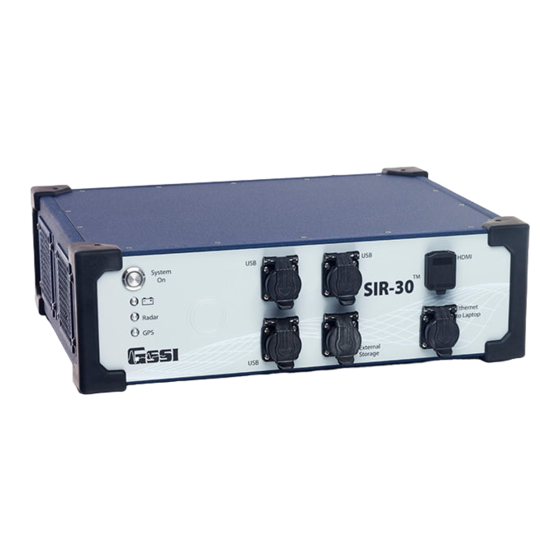
Geophysical Survey Systems, Inc. SIR® 30 Manual Appendix A: SIR 30 Pictures Figure 151: Front Panel - Power switch, HDMI video, Ethernet to Laptop, 4 USB ports. Figure 152: Antenna inputs (2 or 4, 4 shown), Survey Wheel, Marker, DC Power Input, Serial RS232 - GPS port, Sync connector, Accessory connector. - Page 108 Geophysical Survey Systems, Inc. SIR® 30 Manual Figure 154: SIR 30 Mounting options with Universal Mounting Kit. Figure 155: SIR 30 Floor mount. MN 93-101 Rev E...
- Page 109 Geophysical Survey Systems, Inc. SIR® 30 Manual SIR 30 Operational Setups Laptop/PC controlled Standalone with Monitor, mouse and Keyboard Laptop/PC controlled with a remote command set MN 93-101 Rev E...
- Page 110 4 channel Ethernet Switch 8 channel Ethernet Switch SIR 30 Specifications Power: AC supply 95-250VAC 50/60HZ 260W max. DC operating voltage range +10 to +28VDC max 26A @ 10VDC. Weight: 18.5 lbs (8.4 kg) Operating Temperature: -10oC to 40oC external Storage Temperature: -40oC to 60oC Relative Humidity: <95% non-condensing...
-
Page 111: Appendix B: Data Formats
Note: This information is provided to the User for informational use only. It is not supported by GSSI technical support and is provided for those Users who are proficient in working in a C programming environment. - Page 112 // samples per scan short rh_bits; // bits per data word (8,16, 32) * short rh_zero; // if rh_system is SIR 30, // then equals repeats/sample // otherwise is 0x80 for 8 bit data and // 0x8000 for 16 bit data FLOATBYTE(rhf_sps);...
- Page 113 SIR 2000 SIR 3000 TerraVision SIR 20 SS Mini SIR 30 RADAN DZX File Description Version 1.02 3/1/12 Purpose The RADAN DZX file is an XML file used to store all information related to a RADAN DZT file that is not contained in the DZT file.
- Page 114 Geophysical Survey Systems, Inc. SIR® 30 Manual ChannelProperties: The Channel properties element contains child elements that describe the antenna position(s) relative to the GPS or Local 3D coordinates specified in the WayPt elements (which are discussed later). Typically, when a file is collected with GPS, the ChannelProperties element contains the positions of the antennas relative to the GPS location.
- Page 115 Geophysical Survey Systems, Inc. SIR® 30 Manual DZX XML Schema The schema below was created by opening a DZX file in Microsoft Visual Development Studio 2010 Ultimate. It contains all the major elements used for files opened in RADAN 7. <?xml version="1.0"...
- Page 116 Geophysical Survey Systems, Inc. SIR® 30 Manual <xs:element name="hide" type="xs:unsignedByte" /> <xs:element name="localGain" type="xs:decimal" /> <xs:element name="displayOrder" type="xs:unsignedByte" /> <xs:element name="flipDataInVertDir" type="xs:unsignedByte" /> <xs:element name="flipDataInHorizDir" type="xs:unsignedByte" /> </xs:sequence> </xs:complexType> </xs:element> <xs:element maxOccurs="unbounded" name="LocalGlobalCoordSync"> <xs:complexType> <xs:sequence> <xs:element name="scan" type="xs:unsignedByte" /> <xs:element name="name"...
- Page 117 Geophysical Survey Systems, Inc. SIR® 30 Manual <xs:element name="readOnly" type="xs:unsignedByte" /> <xs:element name="diameter" type="xs:decimal" /> <xs:element name="link" type="xs:unsignedByte" /> <xs:element name="pickType" type="xs:unsignedByte" /> <xs:element name="layerNum" type="xs:unsignedByte" /> <xs:element name="velMethod" type="xs:unsignedByte" /> <xs:element name="lockVelocity" type="xs:unsignedByte" /> <xs:element name="defaultVelocity" type="xs:decimal" /> <xs:element minOccurs="0"...
- Page 118 Geophysical Survey Systems, Inc. SIR® 30 Manual <xs:element name="sizePx" type="xs:unsignedByte" /> <xs:element name="outline" type="xs:unsignedByte" /> <xs:element name="readOnly" type="xs:unsignedByte" /> <xs:element name="diameter" type="xs:decimal" /> <xs:element name="link" type="xs:unsignedByte" /> <xs:element maxOccurs="unbounded" name="FreeDrawWayPt"> <xs:complexType> <xs:sequence> <xs:element name="localCoords" type="xs:string" /> <xs:element name="globalCoords" type="xs:string" /> <xs:element name="time"...
-
Page 119: Appendix C: Antenna Specifications
Geophysical Survey Systems, Inc. SIR® 30 Manual Appendix C: Antenna Specifications Center Frequency Model # Pulse Width (nS) Max PRF* (*KHz) (MHz) 4105(NR)/42000 2000 50400A 50400 5104 5106 5100B 1600 52600 2600 4108 1000 3101A 3200MLF 16-80 3207 MN 93-101 Rev E... - Page 120 Geophysical Survey Systems, Inc. SIR® 30 Manual MN 93-101 Rev E...
-
Page 121: Appendix D: Dielectric Values Of Common Materials
Geophysical Survey Systems, Inc. SIR® 30 Manual Appendix D: Dielectric Values of Common Materials Material Dielectric Velocity Shale (wet) (mm/ns) Sandstone (wet) Coal 4 – 5 134 – 150 Water (fresh) Quartz Water (sea) Concrete 5 – 8 55 – 120 Polar snow 1.4 –... - Page 122 Geophysical Survey Systems, Inc. SIR® 30 Manual MN 93-101 Rev E...
-
Page 123: Appendix E: Sir 30 Maintenance Tool Overview
Each version released will come with a document explaining what steps need to be taken to push the changes to the SIR 30. SIR 30 Updater: If you plug the utility into the SIR 30 and ckick Update SIR 30 UI, it will allow you to update the software on the SIR 30 unit. - Page 124 Obtaining the Latest SIR 30 Software, Firmware and Maintenance Utilities Distribution You may have received the maintenance tool with your SIR 30 unit. You can also download the latest SIR 30 Maintenance package from support.geophysical.com. GSSI recommends downloading the latest version.
- Page 125 SIR 30 Maintenance tool available. Note: It may take 30 seconds after you click OK to bring up the SIR 30 Updates Dialog. If a newer version is found it will ask you if you want to download the latest version.
- Page 126 Make certain you have a current version of the SIR 30 maintenance utility. Follow section obtaining the latest SIR 30 maintenance utilities distribution if you have not already done so. Connect SIR 30 to Monitor keyboard and mouse and turn on the SIR 30 control unit. Wait for it to turn on.
- Page 127 Updating SIR 30 Software with the Maintenance Utility The utility is designed to efficiently aid the User in the task of updating SIR 30 Software. If the SIR 30 is operating as a client computer, the SIR 30 control unit may require a direct update .
- Page 128 Follow the instructions :Obtaining the latest SIR 30 software/firmware distribution” if you have not already done so. Connect SIR 30 to your client using Ethernet cable and turn on the SIR 30 and the client. Wait for both to turn on.
- Page 129 Updating SIR 30 Firmware with the Maintenance Utility After you update the Software on both SIR 30 Control Unit (host) and optional client computer and have recorded the current Firmware versions, you may need to install the latest version of firmware. Firmware is always installed to both RADAR1 and RADAR2.
- Page 130 2channel system or RADAR1 and RADAR2 if you have a 4 channel system. Compare these versions to the versions listed in the SIR 30 Release Notes. It is not necessary to change the version of the boot loader.
- Page 131 Click Done when you have completed Parts 1-3 (DO NOT TURN THE SYSTEM OFF). Exit the UI (DO NOT TURN THE SYSTEM OFF) and then run the SIR 30 UI using Prep for System Upgrades button from the Maintenance tool.
- Page 132 SIR 30_Admin user during the out of box experience. Create a user named test during the out of box experience. By doing so you will allow the maintenance tool to create a properly formatted SIR 30 user by following the instructions below.
- Page 133 If you do not see the Computer/User/Group tab on top, select it. Click the Set Workgroup Name button. Click the Create User, Password, Group button. Do this even if you have created the SIR 30 admin user during the Windows out of box experience.
- Page 134 Step 3: Modify the Network On the Network Tab use the control at the bottom left to specify the SIR 30 you want to connect to then enter the serial number in place of “XXX” and select Connect to Server ID0 (Ch 1-4).
- Page 135 Click the On button and then Re/Install SIR 30 Software (wait for completion). Register Server. Copy Shortcuts - After copying the shortcuts you need to right-click on one of the SIR 30 shortcuts and set the Properties > Configuration > Run As Administrator flag.
- Page 136 Troubleshooting SIR 30 Client Computer Connectivity Issues Requirements for Connectivity • SIR 30 with: • Computer Name: SIR 30-SNYYY where YYY is the last 3 digits of the serial number • User Name: SIR 30_Admin • Password: SIR • SIR4xSvr DCOM settings to match above* •...
- Page 137 Manual • Ethernet cable to connect SIR 30 and Client computer (If you have it on a network, check that it works with a direct connection before contacting GSSI. If you are running it through a switch, you will need to troubleshoot any switch connectivity issues with your IT department.) •...
- Page 138 Client). The Maintenance tool cannot access it. The setting has been applied at the factory by GSSI but if it is changed or if SIR 30 software is uninstalled on the SIR 30 Host, it would need to be set up by hand.
- Page 139 Geophysical Survey Systems, Inc. SIR® 30 Manual When the Properties dialog appears, select the Identity tab. The user that needs to be specified must • User: SIR 30_Admin • Password: SIR Confirm Password: SIR It is easier to type it in directly rather than using the Browse button. MN 93-101 Rev E...
- Page 140 When the User has finished adding the information, select OK to apply it. Troubleshooting SIR 30 Update Issues Make sure the client is properly connected and paired to the SIR 30, and that both are turned on. Make sure the maintenance utility is running on the client side.
-
Page 141: Appendix F: Sir 30 Wiring Instructions
SIR® 30 Manual Appendix F: SIR 30 Wiring Instructions The SIR30 runs with a DC input from +10VDC to +28VDC. It will not turn on unless there is a minimum of +10V at the power connector. The system will shut down immediately if the input drops below +9V under load. - Page 142 If custom wiring is to be used to power the unit in a +12V application the wire must be rated for 30A and all 4 INPUT terminals wired. The GSSI cable uses 4 x 12AWG stranded conductors and this should be suitable for 20 feet of cable length.
-
Page 143: Appendix G: Cable Diagrams
Geophysical Survey Systems, Inc. SIR® 30 Manual Appendix G: Cable Diagrams Figure 167: SIR 30 DC\Power Pin out. MN 93-101 Rev E... - Page 144 Geophysical Survey Systems, Inc. SIR® 30 Manual Figure 168: SIR 30 Cable Pin out. MN 93-101 Rev E...
- Page 145 Geophysical Survey Systems, Inc. SIR® 30 Manual Figure 169: Cable Selection Guide. MN 93-101 Rev E...
- Page 146 Geophysical Survey Systems, Inc. SIR® 30 Manual Figure 170: Survey Wheel and Model 10 Marker Pin Out. MN 93-101 Rev E...
- Page 147 Geophysical Survey Systems, Inc. SIR® 30 Manual Figure 171: Serial Port \GPS Pin out. MN 93-101 Rev E...
- Page 148 Geophysical Survey Systems, Inc. SIR® 30 Manual MN 93-101 Rev E...
-
Page 149: Appendix F: Glossary Of Terms
Geophysical Survey Systems, Inc. SIR® 30 Manual Appendix F: Glossary of Terms Antenna: a paired transmitter and receiver that sends electromagnetic energy into a material and receives any reflections of that energy from materials in the ground. Also called a transducer. Antennae are commonly referred to by their center frequency value (i.e. - Page 150 Geophysical Survey Systems, Inc. SIR® 30 Manual Nano-second: unit of measurement for recording the time delay between transmission of a radar pulse and reception of that pulse’s reflections. Equal to one one-billionth of a second. Noise: unwanted background interference that can obscure true data. Noise floor: the noise floor is a measure of the summation of all the noise sources and unwanted signals generated within the data acquisition and signal processing system.
Need help?
Do you have a question about the SIR 30 and is the answer not in the manual?
Questions and answers