
Subscribe to Our Youtube Channel
Related Manuals for Newworld NW 90DFDO


Summary of Contents for Newworld NW 90DFDO
-
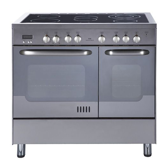
Page 1: Double Oven
DOUBLE OVEN DUAL FUEL COOKER NW 90DFDO Instructions for use - Installation advice... - Page 2 Dear Customer, Thank you for purchasing a NEW WORLD Double Oven Dual Fuel Cooker. The safety precautions and recommendations in these instructions are for your own safety and that of others. They will also provide a means by which to make full use of the features offered by your appliance.
- Page 3 Important: This appliance is designed and manufactured solely for the cooking of domestic (household) food and is not suitable for any non domestic application and therefore should not be used in a commercial environment. The appliance guarantee will be void if the appliance is used within a non domestic environment i.e.
- Page 4 IMPORTANT SAFEGUARDS WARNING When correctly installed, your product AND RECOMMENDATIONS meets all safety requirements laid down for this type of product category. After unpacking the appliance, check to However special care should be taken ensure that it is not damaged and that around the rear or the underneath of the the oven doors close correctly.
-
Page 5: Cooking Hob
COOKING HOB Fig. 1.1 COOKING HOB 1. Auxiliary burner (A) 1,00 kW 2. Semi-rapid burner (SR) 1,75 kW 3. Rapid burner (R) 3,00 kW 4. Triple-ring burner (TR) 3,50 kW Important Note: The electric ignition is incorporated in the knobs. -
Page 6: Control Panel
CONTROL PANEL Fig. 2.1 CONTROL PANEL - Controls description 1. Electronic clock 2. Fan main oven temperature knob 3. Fan main oven switch knob 4. Front left burner control knob 5. Rear left burner control knob 6. Central burner control knob 7. -
Page 7: Use Of Cooking Hob
USE OF COOKING HOB GAS BURNERS Each burner is controlled by a gas tap which opens and closes the gas supply. Turning the knob so that the indicator line points to the symbols printed on the panel achieves the following functions: –... -
Page 8: Lighting The Burners
LIGHTING THE BURNERS CHOICE OF THE BURNER To ignite the burner, the following On the control panel, near each knob, instructions are to be followed: there is a diagram that indicates which burner is controlled by that knob. 1) Lightly press and turn the knob anti- Select the burner that is most suitable clockwise (fig. -
Page 9: General Features
LEFT MAIN FAN OVEN OPERATING PRINCIPLES Attention: the oven door becomes Cooking functions available in this cavity very hot during operation. are: Keep children away. a. Fanned oven The element and the fan work together to produce even results - with no need GENERAL FEATURES to pre-heat. -
Page 10: Thermostat Knob
THERMOSTAT KNOB (Fig. 4.1) This only sets the cooking temperature and does not switch the oven on. Rotate clock- wise until the required temperature is reached (from 50 to 250°C). The light above the thermostat control knob will illuminate when the oven is switched on and turns off when the oven reaches the correct temperature. -
Page 11: Cooking Advice
GRILLING The infra-red heating element is switched on. Use with the function selector knob to position and the thermostat knob between 50°C and 225°C for max 15 minutes, then to position 175°C. The oven door must be closed. For correct use see chapter “USE OF THE GRILL” Before using the grill, preheat for about five minutes. -
Page 12: Oven Cooking
REGENERATION Set the switch to position and the thermostat knob to position 150° C. Bread becomes fragrant again if wet with a few drops of water and put into the oven for about 10 minutes at the highest temperature. ROASTING To obtain classical roasting, it is necessary to remember: –... - Page 13 GRILL PAN AND BAKING TRAY Grilling In order to get the best results from your grill, please grill in the grill area - as shown in the illustration 4.3 - this will given the most even results in the shortest time. Baking In order to achieve optimum results while baking, we recommend that you place your baking tin / tray on top of the grill pan and grid inside the oven.
- Page 14 RIGHT SMALL CONVENTIONAL OVEN ELECTRICAL THERMOSTAT Attention: the oven door becomes Turn on the oven elements by turning the very hot during operation. switch that is also provided with a thermo- Keep children away. stat to control the oven temperature. On the control knob (fig.
-
Page 15: Cooking Guide
COOKING GUIDE Temperature and times given are approximate, as they will vary depending on the quality and amount of food being cooked. Remember to use ovenproof dishes and to adjust the oven temperature during cooking if necessary. COOKING CHART Temperature Food Cooking Time (approx) °C... -
Page 16: Electronic Clock
ELECTRONIC CLOCK ELECTRONIC CLOCK USING THE MINUTE MINDER The minute minder can be set for a This appliance comes with an electronic maximum of 99 minutes. 24 hour clock with minute minder. To set the minute minder, press the plus and minus buttons until the desire length of time is set. -
Page 17: Cleaning And Maintenance
CLEANING AND MAINTENANCE IMPORTANT NOTES IMPORTANT: Installation, and any demonstration, infor- Before cleaning or carrying out mation or adjustments are not included in any maintenance disconnect the the warranty. appliance from the electrical sup- ply and wait for it to cool down. The cooker must be installed by a quali- fied person in accordance with the Gas Attention... -
Page 18: Enamelled Parts
ENAMELLED PARTS REPLACING THE OVEN LIGHT BULB (Left main oven only) All the enamelled parts must be cleaned with a sponge and soapy water or other Switch the cooker off at the mains. non-abrasive products. When the oven is cool, unscrew and Dry preferably with a soft cloth. - Page 19 BURNERS CORRECT REPLACEMENT OF THE BURNERS The burners can be removed and washed with soapy water only. It is very important to check that the They will remain perfect if always burner flame distributor F and the cap C cleaned with products used for silver- has been correctly positioned (see figs.
- Page 20 TRIPLE RING BURNER The triple ring burner must be correctly positioned (see fig. 8.3); the burner rib must be enter in their logement as shown by the arrow. The burners must be correctly positioned so that they cannot rotate (fig. 8.4). Then position the cap A and the ring B (fig.
-
Page 21: Storage Compartment
OVEN DOOR STORAGE COMPARTMENT The storage compartment is accessible The internal glass panel can be easily through the pivoting panel (fig. 8.7). removed for cleaning by unscrewing the 2 retaining screws (Fig. 8.6). Do not store flammable material in the oven or in the storage com- partment. - Page 22 INSIDE OF OVEN ASSEMBLY AND DISMANTLING OF THE SIDE RUNNER FRAMES This must be cleaned after every use. Remove and refit the side runner frames – Fit the side runner frames into the as described on the next chapter. holes on the side walls inside the Wipe the inside walls with a cloth oven (Fig.
-
Page 23: Removing The Oven Door
REMOVING THE OVEN DOOR Fig. 8.10A The oven door can easily be removed as follows: – Open the door to the full extent (fig. 8.10A). – Attach the retaining rings to the hooks on the left and right hinges (fig. 8.10B). –... - Page 24 Advice for the installer IMPORTANT – Cooker installation must only be carried out by QUALIFIED TECHNICIANS and in compliance with local safety standards. Failure to observe this rule will invalidate the warranty. The appliance must be installed in compliance with regulations in force in your country and in observation of the manufacturer's instructions.
-
Page 25: Installation
INSTALLATION The cooker must be installed by a qualified technician and in compliance with local safety standards. This cookers has class “2/1” overheating protection so that it can be installed next to a cabinet. If the cooker is installed adjacent to furniture which is higher than the gas hob cooktop, a gap of at least 200 mm must be left between the side of the cooker and the furniture. -
Page 26: Fitting The Adjustable Feet
BACKGUARD – Remove the two spacers “A” and the screw “B” from the rear of the cooker top. – Assemble the backguard as shown in figure 9.2 and fix it by screwing the central screw “B” and the spacers “A”. Fig. -
Page 27: Moving The Cooker
MOVING THE COOKER WARNING When raising cooker to upright posi- tion always ensure two people carry out this manoeuvre to prevent dam- age to the adjustable feet (fig. 9.5). WARNING Be careful: do not lift the cooker by the door handle when raising to the upright position (fig. -
Page 28: Provision For Ventilation
PROVISION FOR VENTILATION The room containing the cooker should have an air supply in accordance with BS.5540: Part 2: 1989. All rooms require an openable window or equivalent while some rooms require a permanent vent in addition to the openable window. The cooker should not be installed in a bed-sitting room, of volume less than 21 m Where a DOMESTIC COOKER is installed in a room or internal space, that room or internal space shall be provided with a permanent opening which communicates directly... -
Page 29: Gas Section
GAS SECTION GAS INSTALLATION GAS CONNECTION IMPORTANT NOTE The installation of the cooker to Natural Gas or LP Gas must be carried out by a This appliance is supplied for use on qualified gas engineer. Installers shall NATURAL GAS only and cannot be take due account of the provisions of used on any other gas without modifica- the relevant British Standards Code of... - Page 30 GAS CONNECTION The gas supply must use the nearest gas inlet pipe which is located at the left or the right hand side at the rear of the appliance (fig. 10.2). IMPORTANT NOTE: Before connecting the appliance to the gas mains fit the female connector (supplied with the appliance in a separate kit) to the right or the left inlet pipe interposing the gasket.
- Page 31 Right gas inlet pipe Left gas inlet pipe Plug Connector Fig. 10.2 IMPORTANT PRESCRIPTIONS FOR GAS CONNECTION Rear wall Suggested area for gas mains connection Fig. 10.3...
-
Page 32: Conversion To Lpg
CONVERSION TO LPG INJECTORS REPLACEMENT OF THE TOP BURNERS If the injectors are not supplied they can be obtained from the “Service Centre”. The diameter is marked on the injector in cents of millimetre. Select the injectors to be replaced according to the “Table for the choice of the injectors”... -
Page 33: Lubrication Of The Gas Taps
TABLE FOR THE CHOICE OF THE INJECTORS Cat: 2H3+ G30/G31 G 20 Nominal Reduced BURNERS 28-30/37 mbar 20 mbar Power Power Ø injector By-pass Ø injector By-pass [kW] [kW] [1/100 mm] [1/100 mm] [1/100 mm] [1/100 mm] Auxiliary (A) 1,00 0,30 72 (X) Semi-rapid (SR) -
Page 34: Electrical Section
ELECTRICAL SECTION N.B. For connection to the mains, do not use adapters, reducers or IMPORTANT: The cooker must branching devices as they can cause be installed in accordance with overheating and burning. the manufacturer’s instructions. Incorrect installation, for which If the installation requires alterations to the manufacturer accepts no the domestic electrical system, call an responsibility, may cause injury... - Page 35 ELECTRICAL FEEDER CABLE FEEDER CABLE SECTION TYPE CONNECTION HO5RR-F To connect the supply cable: 230 V 3 x 2,5 mm (**) - Remove the screws securing the cover “A” on the rear of the cooker (**) – Connection to wall- mounting dis- (fig.
- Page 36 Descriptions and illustrations in this booklet are given as simply indicative. The manufacturer reserves the right, considering the characteristics of the models described here, at any time and without notice, to make eventual necessary modifications for their construction or for commercial needs. Cod.
Need help?
Do you have a question about the NW 90DFDO and is the answer not in the manual?
Questions and answers