Table of Contents
Advertisement
Quick Links
Advertisement
Table of Contents

Related Manuals for Grundfos DDA 7.5-16


Summary of Contents for Grundfos DDA 7.5-16
- Page 1 GRUNDFOS INSTRUCTIONS SMART Digital - DDA Installation and operating instructions...
-
Page 3: Table Of Contents
English (GB) Installation and operating instructions Analog output Original installation and operating instructions. SlowMode CONTENTS FlowControl Pressure monitoring Page 6.8.1 Pressure setting ranges Safety instructions 6.8.2 Calibration of pressure sensor Symbols used in this document Flow measurement Qualification and training of personnel AutoFlowAdapt 6.10 Safety instructions for the operator/user... -
Page 4: Safety Instructions
1. Safety instructions 1.3 Safety instructions for the operator/user These installation and operating instructions contain general instructions that must be observed during The safety instructions described in these installation, operation and maintenance of the pump. instructions, existing national regulations on health It must therefore be read by the installation engineer protection, environmental protection and for accident and the relevant qualified operator prior to... -
Page 5: Dosing Chemicals
Should you have any questions • Never operate the pump with damaged or loose regarding the material resistance and dosing head screws. suitability of the pump for specific dosing media, please contact Grundfos. -
Page 6: General Information
Grundfos cannot be held • Continuous dosing, as the medium is sucked up liable for any damage resulting from with a short suction stroke, regardless of the incorrect use. -
Page 7: Symbols On The Pump
2.3 Symbols on the pump Symbol Description Indication of universally dangerous spot. In case of emergency and prior to all maintenance work and repairs, take the mains plug out of the mains supply! The device complies with electrical safety class II. Connection for deaeration hose at dosing head. -
Page 8: Type Key
Hose, 3/8" x 1/2" (up to 60 l/h, 10 bar) Mains plug USA, Canada Australia, New Zealand, Taiwan Switzerland Japan Argentina Design Grundfos including: 2 pump connections, foot valve, injection unit, 6 m PE discharge hose, 2 m PVC suction hose, 2 m PVC deaeration hose (4/6 mm) -
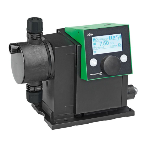
Page 9: Product Overview
2.7 Product overview Control cube Graphic LC display (section 6.2.2) Click wheel (section 6.1) [Start/stop] key (section 6.1) [100%] key (section 6.1) 100% 100% Signal inputs/outputs (section 4.3) Mains connection Mounting plate Fig. 2 Front view of the pump Valve, discharge side Control cube assembly screws Deaeration valve... -
Page 10: Technical Data / Dimensions
3. Technical data / Dimensions 3.1 Technical data Data 7.5-16 12-10 17-7 30-4 Turndown ratio (setting range) [1:X] 3000 1000 1000 1000 [l/h] 12.0 17.0 30.0 Max. dosing capacity [gph] [l/h] 3.75 6.00 8.50 15.00 Max. dosing capacity with SlowMode 50 % [gph] 1.00 1.55... - Page 11 Data 7.5-16 12-10 17-7 30-4 100-240 V, - 10 %/+ 10 %, Voltage 50/60 Hz Length of mains cable Max. inrush current for 2 ms (100 V) Electrical Max. inrush current for 2 ms (230 V) data Max. power consumption P Enclosure class IP65, Nema 4X Electrical safety class...
-
Page 12: Dimensions
3.2 Dimensions 17.5 G 5/8" 100% 4 x Ø6 Fig. 4 Dimensional sketch Pump type A [mm] A1 [mm] B [mm] C [mm] D [mm] DDA 7.5-16 46.5 DDA 12-10/17-7 200.5 39.5 DDA 30-4 204.5 35.5 38.5... -
Page 13: Assembly And Installation
4. Assembly and installation 4.1.3 Engage pump in mounting plate 1. Attach the pump to the mounting plate support For use in Australia: clamps and slide under slight pressure until it engages. Installation of this product must comply with AS/NZS3500! Note Certificate of suitability number: CS9431... -
Page 14: Hydraulic Connection
(approx. 3 bar) on with a suction line, level switch and multifunction the discharge side for the safe generation of the valve on a Grundfos tank. necessary differential pressure. Multifunction valve... -
Page 15: Electrical Connection
4.3 Electrical connection Warning The enclosure class (IP65/Nema 4X) is only guaranteed if plugs or protective caps are correctly installed! Warning The pump can start automatically when the mains voltage is switched on! Do not manipulate mains plug or cable! The mains plug is the separator separating the pump from the mains. - Page 16 Analog, External stop and pulse input Pins Function Plug type 1/brown 2/white 3/blue 4/black Analog GND/(-) mA (+) mA mA signal External stop Pulse Pulse Pulse Level signals: Empty signal and Low-level signal Pins Function Plug type Low-level signal Pulse Empty signal Pulse GENIbus, Analog output...
-
Page 17: Startup
5. Startup 5.1 Setting the menu language For description of control elements, see section 6. 1. Turn click wheel to highlight the cog symbol. Operation 7.50 Manual Operation 2. Press the click wheel to open the "Setup" menu. 7.50 Manual Setup 3. -
Page 18: Deaerating The Pump
5.2 Deaerating the pump Warning The deaeration hose must be connected correctly and inserted into a suitable tank! 1. Open deaeration valve by approximately half a turn. 2. Press and hold down the [100%] key (deaeration key) until liquid flows continuously without any bubbles from the deaeration hose. - Page 19 Calibration process - example for DDA 7.5-16 1. Fill a measuring beaker with dosing medium. Recommended filling volumes V – DDA 7.5-16: 0.3 l – DDA 12-10: 0.5 l = 300 ml – DDA 17-7: 1.0 l – DDA 30-4: 1.5 l 2.
-
Page 20: Operation
6. Operation 6.2 Display and symbols 6.2.1 Navigation 6.1 Control elements In the "Info", "Alarm" and "Setup" main menus, the The pump control panel includes a display options and submenus are displayed in the rows and the following control elements. below. -
Page 21: Overview Of Display Symbols
6.2.4 Overview of display symbols The following display symbols may appear in the menus. Top row with main menus (Sect. 6.3) Operation Back Info Alarm Run display Running - rotates when pump is dosing Setup Blocked drive - flashing symbol Operation 7.48 Manual... -
Page 22: Main Menus
6.3.3 Alarm 6.3 Main menus You can view errors in the "Alarm" main The main menus are displayed as symbols at the top menu. of the display. The currently active main menu is displayed as text. Alarm 6.3.1 Operation Status information such as the dosing flow, 12.02.2010 12:34 selected operation mode and operating state... -
Page 23: Operation Modes
3.40 range for the dosing volume depends on the pump type: Manual 3.40l/h Type Setting range [ml/pulse] DDA 7.5-16 0.0015 - 14.9 Manual mode Fig. 15 DDA 12-10 0.0029 - 29.0 The setting range depends on the pump type: DDA 17-7 0.0031 - 31.0... -
Page 24: Analog 0/4-20 Ma
), which are set in the "Setup mode [mA] > Analog scaling" menu. The dosing flow is controlled according to this setting. ≤ 4.1 4-20 mA Example 1 (DDA 7.5-16) ≥ 19.8 Analog scaling with positive gradient: ≤ 0.1 0-20 mA ≥ 19.8 Q [l/h]... -
Page 25: Batch (Pulse-Based)
Pulse Pulse Batch (pulse-based) Fig. 22 The setting range depends on the pump type: Setting range per batch Type Resolution* from [ml] to [l] [ml] DDA 7.5-16 0.74 0.0925 DDA 12-10 1.45 0.1813 DDA 17-7 1.55 0.1938 DDA 30-4 3.10 0.3875... -
Page 26: Dosing Timer Cycle
6.4.5 Dosing timer cycle The total batch volume (e.g. 125 ml) and the remaining batch volume still to be dosed are In this operation mode, the pump doses the displayed in the "Operation" menu. During breaks in set batch volume in regular cycles. dosing, the time until the next dosing process Dosing starts when the pump is started after a (e.g. -
Page 27: Analog Output
6.5 Analog output The following settings are required in the "Setup > Dosing timer week" menu for each dosing procedure: Analog out Timer Output = Input Procedure Actual flow ❑ Batch volume 80.5ml Backpressure ❑ Dosing time[s] 39.0 Bus control ❑... -
Page 28: Slowmode
6.6 SlowMode When the "SlowMode" function is enabled, the pump slows down the suction stroke. The function is enabled in the "Setup > SlowMode" menu and is used to prevent cavitation in the following cases: • for dosing media with a high viscosity •... -
Page 29: Flowcontrol
6.7 FlowControl FlowControl works with a maintenance-free sensor in the dosing head. During the dosing process, the Applies to DDA-FC/FCM control variant. sensor measures the current pressure and This function is used to monitor the dosing process. continuously sends the measured value to the Although the pump is running, various influences microprocessor in the pump. -
Page 30: Pressure Monitoring
"! "Suction valve removed?" 6.8.1 Pressure setting ranges Sensor not calibrated. Fixed min. Adjustable max. Type Calibration error pressure [bar] pressure [bar] DDA 7.5-16 < 2 3-17 Message: Message: DDA 12-10 < 2 3-11 "Sensor calib. OK!" "Sensor calib. failed!"... -
Page 31: Flow Measurement
6.9 Flow measurement Example of "AutoFlowAdapt" Pressure fluctuations Applies to DDA-FCM control variant. The dosing volume decreases as backpressure The pump accurately measures the actual flow and increases and conversely the dosing volume displays it. Via the 0/4-20 mA analog output, the increases as the backpressure decreases. -
Page 32: Display Setup
6.13 Display Setup The additional display can be set as follows: Use the following settings in the "Setup > Display" Setting Description menu to adjust the display properties: • Units (metric/US) Depending on the operation mode: • Display contrast 1), 2) Actual flow (Manual/Pulse) •... -
Page 33: Bus Communication
DP E-Box 150 V2.0 and higher Modbus RTU E-Box 200 V2.5 and higher The pump can also be connected to a Grundfos CIU unit (CIU = Communication Interface Unit) equipped with one of the following CIM modules (CIM = Communication Interface Module): •... -
Page 34: Characteristics Of Bus Communication
6.15.5 Characteristics of bus communication 6.15.7 Communication faults To start and stop the pump via bus, it needs to be in Faults are only detected, if the respective operating state "Running". When the pump is "BusWatchDog" (see functional profile on E-Box/CIU remotely stopped from bus, the "External stop"... -
Page 35: Inputs/Outputs
6.16 Inputs/Outputs 6.16.1 Relay outputs The pump can switch two external signals using In the "Setup > Inputs/Outputs" menu, you can installed relays. The relays are switched by configure the two outputs "Relay 1+Relay 2" and the potential-free pulses. The connection diagram of the signal inputs "External stop", "Empty signal"... -
Page 36: External Stop
Timer Cycle (Relay 2) 6.16.3 Empty and Low level signals For the "Relay 2 > Timer Cycle" function, set the In order to monitor the filling level in the following parameters: tank, a dual-level sensor can be connected to the pump. -
Page 37: Service
7. Service 7.3 Service system According to the motor runtime or after a defined In order to ensure a long service life and period of operation, service requirements will dosing accuracy, wearing parts such as appear. Service requirements appear regardless of diaphragms and valves must be regularly checked the current operating state of the pump and do not for signs of wear. -
Page 38: Perform Service
7.4 Perform service 7.4.2 Dismantling the diaphragm and valves Only spare parts and accessories from Grundfos Warning should be used for maintenance. The usage of Danger of explosion, if dosing liquid non-original spare parts and accessories renders has entered the pump housing! any liability for resulting damages null and void. -
Page 39: Reassembling The Diaphragm And Valves
7.4.3 Reassembling the diaphragm and valves 7.6 Diaphragm breakage The pump must only be reassembled, if nothing If the diaphragm leaks or is broken, dosing liquid indicates that dosing liquid has entered the pump escapes from the drain opening (fig. 41, pos. 11) on housing. -
Page 40: Dismantling In Case Of Diaphragm
9. Make sure the drain opening (11) is not blocked or soiled. Clean if necessary. If the above requirements are not met, Grundfos may 10. Check the safety diaphragm (1) for wear and refuse to accept delivery of the pump. The shipping damage. -
Page 41: Faults
8. Faults In the event of faults in the dosing pump, a warning or an alarm is triggered. The corresponding fault symbol flashes in the "Operation" menu, see section 8.1 List of faults. The cursor jumps to the "Alarm" main menu symbol. Press the click wheel to open the "Alarm"... -
Page 42: List Of Faults
8.1 List of faults 8.1.1 Faults with error message Display in the Possible cause Possible remedy "Alarm" menu Empty • Dosing medium tank empty • Fill tank. (Alarm) • Check contact setting (NO/NC). Low level • Dosing medium tank almost empty (Warning) •... -
Page 43: General Faults
Display in the Possible cause Possible remedy "Alarm" menu • Broken "FlowControl" cable (see • Check plug connection. fig. 11) • Change sensor if necessary. Pressure sensor • Sensor defect • Calibrate pressure sensor correctly (see (Warning) • Pressure sensor not correctly section 6.8.2 Calibration of pressure calibrated. -
Page 44: Disposal
7.4 Perform service). 9. Disposal This product or parts of it must be disposed of in an environmentally sound way. Use appropriate waste collection services. If this is not possible, contact the nearest Grundfos company or service workshop. Subject to alterations. - Page 45 Appendix Safety declaration Please copy, fill in and sign this sheet and attach it to the pump returned for service. Fill in this document using English or German language. Note Product type (nameplate) Model number (nameplate) Dosing medium Fault description Please make a circle around the damaged parts.
-
Page 46: Declaration Of Conformity
DK: EF-overensstemmelseserklæring My firma Grundfos prohlašujeme na svou plnou odpovědnost, Vi, Grundfos, erklærer under ansvar at produkterne DDA, DDC og DDE že výrobky DDA, DDC a DDE, na něž se toto prohlášení vztahuje, jsou som denne erklæring omhandler, er i overensstemmelse med disse af v souladu s ustanoveními směrnice Rady pro sblížení... - Page 47 GR: ∆ήλωση συμμόρφωσης EC ES: Declaración CE de conformidad Εμείς, η Grundfos, δηλώνουμε με αποκλειστικά δική μας ευθύνη ότι Nosotros, Grundfos, declaramos bajo nuestra entera responsabilidad τα προϊόντα DDA, DDC και DDE στα οποία αναφέρεται η παρούσα que los productos DDA, DDC y DDE, a los cuales se refiere esta δήλωση, συμμορφώνονται...
- Page 48 75 V DC. Toto prehlásenie o konformite ES je platné iba vtedy, ak je zverejnené ako súčasť montážnych a prevádzkových pokynov Grundfos. ES izjava o skladnosti velja samo kadar je izdana kot del Grundfos instalacije in navodil delovanja.
- Page 49 CN: EC 产品合格声明书 JP: EC 適合宣言 我们格兰富在我们的全权责任下声明,产品 DDA, DDC 和 DDE,即该 Grundfos は、 その責任の下に、 DDA, DDC 製品お よ び DDE 製品が EC 合格证所指之产品,符合欧共体使其成员国法律趋于一致的以下欧共理 加盟諸国の法規に関連す る 、 以下の評議会指令に適合 し て い る こ と を 事会指令: 宣言 し ます :...
- Page 50 Argentina China Germany Bombas GRUNDFOS de Argentina S.A. Grundfos Alldos GRUNDFOS GMBH Ruta Panamericana km. 37.500 Centro Dosing & Disinfection Schlüterstr. 33 Industrial Garin ALLDOS (Shanghai) Water Technology 40699 Erkrath 1619 - Garin Pcia. de B.A. Co. Ltd. Tel.: +49-(0) 211 929 69-0 Phone: +54-3327 414 444 West Unit, 1 Floor, No.
- Page 51 Fax: + 370 52 395 431 Тел. (+7) 495 737 30 00, 564 88 00 Turkey Факс (+7) 495 737 75 36, 564 88 11 Malaysia GRUNDFOS POMPA San. ve Tic. Ltd. E-mail grundfos.moscow@grundfos.com GRUNDFOS Pumps Sdn. Bhd. Sti. Serbia 7 Jalan Peguam U1/25 Gebze Organize Sanayi Bölgesi...
- Page 52 95724708 1213 ECM: 1125152 www.grundfos.com...
Need help?
Do you have a question about the DDA 7.5-16 and is the answer not in the manual?
Questions and answers