Table of Contents
Advertisement
Quick Links
Advertisement
Table of Contents

Related Manuals for GeoMax Zoom 20 series


Summary of Contents for GeoMax Zoom 20 series
- Page 1 GeoMax Zoom 20/Zoom 30 Series User Manual Version 1.0...
- Page 2 The type and serial number of your product are indicated on the type plate. cation Enter the type and serial number in your manual and always refer to this infor- mation when you need to contact your agency or GeoMax authorised service workshop. Type: _____________________________________ Serial No.:...
- Page 3 Symbols The symbols used in this manual have the following meanings: Type Description Danger Indicates an imminently hazardous situation which, if not avoided, will result in death or serious injury. Warning Indicates a potentially hazardous situation or an unin- tended use which, if not avoided, could result in death or serious injury.
- Page 4 Zoom | 4 Introduction Validity of this Description manual General This manual applies to Zoom 20 and Zoom 30 instru- ments. Where there are differences between the instruments they are clearly described. Telescope • Measuring with IR modes: When measuring distances to a reflector with Electronic Distance Measurement (EDM) mode "IR", the telescope uses a wide visible red laser beam, which emerges...
- Page 5 Warning Zoom_019 Do NOT remove the battery during operation of the instrument, or during the shutdown procedure. This can result in a file system error and data loss! Always switch off the instrument by pressing the On/Off key, and wait until the instrument has shutdown completely before removing the battery.
-
Page 6: Table Of Contents
Zoom | 6 Table of Contents Table of Contents In this manual Chapter Page Description of the System 1.1 System Components 1.2 Container Contents 1.3 Instrument Components User Interface 2.1 Keyboard 2.2 Screen 2.3 Status Icons 2.4 Softkeys 2.5 Operating Principles 2.6 Pointsearch Operation 3.1 Instrument Setup... - Page 7 3.5 Survey Application 3.6 Distance Measurements - Guidelines for Correct Results Settings 4.1 General Settings 4.2 EDM Settings 4.3 Communication Settings Tools 5.1 Calibration 5.2 Auto Start Routine 5.3 System Information 5.4 Loading Software Functions 6.1 Overview 6.2 Distance Offset 6.3 Z-Coordinate 6.4 2 Dist.
- Page 8 Zoom | 8 Table of Contents Applications - Getting Started 8.1 Overview 8.2 Starting an Application 8.3 Selecting the Job 8.4 Selecting the Station 8.5 Selecting the Orientation 8.5.1 Overview 8.5.2 Manual Orientation 8.5.3 Orientation with Coordinates Applications 9.1 Common Fields 9.2 Survey 9.3 Reference Element - Reference Line 9.3.1...
- Page 9 9.4.3 Subapplication Measure Line & Offset 9.4.4 Subapplication Setout 9.5 COGO 9.5.1 Starting COGO 9.5.2 Inverse and Traverse 9.5.3 Intersections 9.5.4 Offsets 9.5.5 Extension 9.6 Missing Line Measurement 9.7 Resection 9.7.1 Starting Resection 9.7.2 Measuring Information 9.7.3 Computation Procedure 9.7.4 Resection Results 9.8 Set Out 9.9 Area &...
-
Page 10: Table Of Contents Zoom
10.1 Data Management 10.2 Exporting Data 10.3 Importing Data 10.4 Working with a USB Memory Stick 10.5 Working with Bluetooth 10.6 Working with GeoMax Geo Office and GGO Tools 11 Calibration 11.1 Overview 11.2 Preparation 11.3 Calibrating Line-of-Sight and Vertical Index Error 11.4 Calibrating the Circular Level of the Instrument and Tribrach... - Page 11 13 Safety Directions 13.1 General 13.2 Intended Use 13.3 Limits of Use 13.4 Responsibilities 13.5 Hazards of Use 13.6 Laser Classification 13.6.1 General 13.6.2 Distancer, Measurements with Reflectors 13.6.3 Distancer, Measurements without Reflectors (Reflectorless mode) 13.6.4 Laser Plummet 13.7 Electromagnetic Compatibility EMC 13.8 FCC Statement, Applicable in U.S.
- Page 12 Zoom | 12 Table of Contents 14.5.1 Zoom 20 14.5.2 Zoom 30 14.6 General Technical Data of the Instrument 14.7 Scale Correction 14.8 Reduction Formulas 15 International Limited Warranty 16 Glossary Appendix A Menu Tree Appendix B Directory Structure Index...
-
Page 13: Description Of The System
1 Description of the System 1.1 System Components Main Compo- nents a) Zoom instrument b) Computer with GGO or GGO Tools software c) Data transfer Zoom_001 Component Description Zoom instru- An instrument for measuring, calculating and capturing data. ment Ideally suited for tasks from simple surveys to complex appli- cations. - Page 14 Zoom | 14 Description of the System Component Description Firmware The firmware package installed on the instrument. Consists of a standard base operating system with optional additional features. GGO or GGO An office software consisting of a suite of standard and Tools soft- extended programs for the viewing, exchanging, managing ware...
-
Page 15: Container Contents
1.2 Container Contents Container contents part 1 of a) Instrument with supplied tribrach b) ZDC100 data cable (USB-RS232)* c) Protective cover Optional Zoom_022a Zoom | 15 Description of the System... - Page 16 Zoom | 16 Description of the System Container contents part 2 of d) Adjustment tools e) ZBA200 battery charger* USB memory stick - for Zoom 30 instruments* g) ZBA400 battery* h) Tip for mini prism pole* User manual GLS115 mini prism pole* Optional Zoom_022...
-
Page 17: Instrument Components
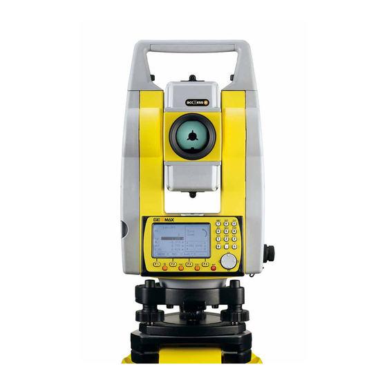
1.3 Instrument Components Instrument components part 1 of 2 a) Detachable carrying handle with mounting screw b) Optical sight c) Objective with integrated Elec- tronic Distance Measurement (EDM). Exit for EDM laser beam d) Vertical drive e) Serial interface RS232/USB USB host port g) Horizontal drive h) Second keyboard*... - Page 18 Zoom | 18 Description of the System Instrument components part 2 of 2 Focusing telescope image Eyepiece; focusing graticule k) Battery cover Foot screw m) Circular level n) Display o) Keyboard Zoom_003...
-
Page 19: User Interface
2 User Interface 2.1 Keyboard Alphanumeric keyboard a) Alphanumeric keypad b) Navigation key c) ENTER key d) Function keys F1 to F4 e) ESC key FNC key g) PAGE key Zoom_009 Keys Description Page key. Displays the next screen when several screens are avail- able. - Page 20 Zoom | 20 User Interface Description Navigation key. Controls the focus bar within the screen and the entry bar within a field. ENTER key. Confirms an entry and continues to the next field. ESC key. Quits a screen or edit mode without saving changes. Returns to next higher level.
-
Page 21: Screen
2.2 Screen Screen a) Title of screen b) Focus in screen. Active field c) Status icons d) Fields e) Softkeys Zoom_032 All shown screens are examples. It is possible that local firmware versions are different to the basic version. Zoom | 21 User Interface... -
Page 22: Status Icons
Zoom | 22 User Interface 2.3 Status Icons Description The icons provide status information related to basic instrument functions. Depending on the firmware version, different icons are displayed. Icons Icon Description The battery symbol indicates the level of the remaining battery capacity, 75% full shown in the example. - Page 23 Icon Description Indicates that horizontal angle is set to left side angle measure- ment (anticlockwise). A double arrow indicates a field has a selectable list. Up and down arrows indicate that several screens are available, which are accessed using Indicates telescope position is face I. Indicates telescope position is face II.
-
Page 24: Softkeys
Zoom | 24 User Interface 2.4 Softkeys Description Softkeys are selected using the relevant F1 to F4 function key. This chapter describes the functionality of the common softkeys used by the system. The more specialised softkeys are described where they appear in the application chapters. - Page 25 Description If entry screen: Confirms measured or entered values and continues the process. If message screen: Confirms message and continues with selected action or returns to the previous screen to reselect an option. IR/RL To toggle between IR and RL EDM modes. DISPL.
-
Page 26: Operating Principles
Zoom | 26 User Interface 2.5 Operating Principles Turn instrument Use the On/Off key. on/off Alphanumeric The alphanumerical keypad is used to enter characters directly into editable keypad fields. • Numeric fields: Can only contain numerical values. By pressing a key of the keypad the number will be displayed. - Page 27 In edit mode the position of the decimal place cannot be changed. The decimal place is skipped. Special charac- Character Description ters Used as wildcards in search fields for point numbers or codes. Refer to "2.6 Pointsearch". In the alphanumeric character set "+" and "-" are treated as normal alphanumeric characters with no mathematical function.
-
Page 28: Pointsearch
Zoom | 28 User Interface 2.6 Pointsearch Description Pointsearch is a function used by applications to find measured or fixed points in the memory storage. It is possible to limit the point search to a particular job or to search the whole storage. - Page 29 Wildcard search The wildcard search is indicated by a "*". The asterisk is a place holder for any following sequence of characters. Wildcards should be used if the point number is not fully known, or to search for a batch of points. Examples of All points are found.
-
Page 30: Operation
Zoom | 30 Operation 3 Operation 3.1 Instrument Setup Description This topic describes an instrument setup over a marked ground point using the laser plummet. It is always possible to set up the instrument without the need for a marked ground point. Important features •... - Page 31 Loosen the clamping screws on the tripod legs, pull out to the required length and tighten the clamps. a) In order to guarantee a firm foothold sufficiently press the tripod legs into the ground. b) When pressing the legs into the ground note that the force must be applied along the legs.
- Page 32 Zoom | 32 Operation Setup step-by- step Zoom_004 Extend the tripod legs to allow for a comfortable working posture. Position the tripod over the marked ground point, centring it as best as possible. Fasten the tribrach and instrument onto the tripod. Turn on the instrument, and, if tilt correction is set to 1- or 2-axis, the laser plummet will be activated automatically, and the Level &...
- Page 33 Center the instrument precisely over the ground point by shifting the tribrach on the tripod plate (2). Repeat steps 6 and 7 until the required accuracy is achieved. Level up with the The electronic level can be used to precisely level up the instrument using the electronic level footscrews of the tribrach.
- Page 34 Zoom | 34 Operation Center the electronic level of the first axis by turning the two footscrews. Arrows show the direction of rotation required. When the electronic level is centered the arrows are replaced by checkmarks. Center the electronic level for the second axis by turning the last foot- screw.
- Page 35 Change the External influences and the surface conditions may require the adjustment of intensity of the the intensity of the laser plummet. laser plummet In the Level & Plummet screen, adjust the intensity of the laser plummet using the navigation key. The laser can be adjusted in 25% steps as required.
-
Page 36: Working With The Battery
+10°C to +20°C/+50°F to +68°F if possible. • It is normal for the battery to become warm during charging. Using the chargers recommended by GeoMax, it is not possible to charge the battery if the temperature is too high. Operation / discharging •... - Page 37 Change the Open the battery compartment (1) battery step-by- step and remove the battery holder. Remove the battery from the battery holder (2). Zoom_006 Insert the new battery into the battery holder (3), ensuring that the contacts are facing outward. The battery should click into position.
- Page 38 Zoom | 38 Operation Warning Batteries not recommended by GeoMax may be damaged if charged or discharged. They may burn and explode. Precautions: Only charge and discharge batteries recommended by GeoMax.
-
Page 39: Data Storage
3.3 Data Storage Description An internal memory is included in all instruments. The firmware stores all data in jobs in a database in the internal memory. Data can then be transferred to a computer or other device for post processing via a cable connected to the serial interface RS232 port. -
Page 40: Main Menu
Zoom | 40 Operation 3.4 Main Menu Description The MAIN MENU is the starting place for accessing all functionality of the instrument. It is usually displayed immediately after the Level & Plummet screen, after switching on the instrument. MAIN MENU Description of the MAIN MENU functions Function Description... - Page 41 Function Description Settings To change EDM configurations, comm.-setup and general instru- ment settings. Refer to "4 Settings". Survey Survey program to begin measuring immediately. Refer to "3.5 Survey Application". Transfer To export and import data. Refer to "10.2 Exporting Data". Tools To access instrument related tools such as calibrations, personal start up settings, licence keys and system information.
-
Page 42: Survey Application
Zoom | 42 Operation 3.5 Survey Application Description After switching on and setting up correctly, the instrument is immediately ready for measuring. Access Select Survey from the MAIN MENU. SURVEY CODING To find/enter codes. Refer to "7 Coding". To enter station data and set the station. - Page 43 The procedure for the quick start Survey is identical to the procedure for the application Survey available under the Apps menu. Therefore this procedure is only described once within the application chapter. Refer to "9.2 Survey". Zoom | 43 Operation...
-
Page 44: Distance Measurements - Guidelines For Correct Results
Zoom | 44 Operation 3.6 Distance Measurements - Guidelines for Correct Re- sults Description A laser distancer (EDM) is incorporated into the Zoom instruments. In all versions, the distance can be determined by using a visible red laser beam which emerges coaxially from the telescope objective. There are two EDM modes: •... - Page 45 instrument and the point to be measured, the EDM may measure to the obstruction. • Be sure that the laser beam is not reflected by anything close to the line of sight, for example highly reflective objects. • Avoid interrupting the measuring beam while taking reflectorless measure- ments or measurements using reflective foils.
- Page 46 Zoom | 46 Operation Red laser to • RL-Long Range mode enables distance measurements of over 3.5 km to prism standard prisms using the visible red laser beam. Red laser to • The visible red laser beam can also be used to measure to reflective foils. reflector foil To guarantee the accuracy the red laser beam must be perpendicular to the reflector foil and it must be well adjusted.
-
Page 47: Settings
4 Settings 4.1 General Settings Access Select Settings from the MAIN MENU. Select General from the SETTINGS menu. Press to scroll through the screens of available settings. SETTINGS DelLng To delete a selected language. Field Description Contrast 0% to 100% Sets the display contrast in 10% steps. Tilt Corr. - Page 48 Zoom | 48 Settings Field Description Single Axis Vertical angles refer to the plummet line. Dual Axis Vertical angles refer to the plummet line and the horizontal directions are corrected by the standing axis tilt. For corrections depending on the HA Corr: setting, refer to the table "Tilt and horizontal corrections".
- Page 49 Field Description Face I Def. Sets the face I in relation to the position of the vertical drive. VA-Left Sets face I to be when the vertical drive is on the left of the instrument. VA-Right Sets face I to be when the vertical drive is on the right of the instrument.
- Page 50 Zoom | 50 Settings Field Description VA-Setting Sets the vertical angle. Zenith Zenith=0°; Horizon=90°. Horizont Zenith=90°; Horizon=0°. Vertical angles are positive above the horizon and negative below it. Slope % Slope % 45°=100%; Horizon=0°. +300 % Vertical angles are expressed --.--% +100% in % with positive above the...
- Page 51 Field Description Angle Unit Sets the units shown for all angular fields. ° ' " Degree sexagesimal. Possible angle values: 0° to 359°59'59'' dec. deg Degree decimal. Possible angle values: 0° to 359.999° Gon. Possible angle values: 0 gon to 399.999 Mil.
- Page 52 Zoom | 52 Settings Field Description Mil: (0.01 / 0.05 / 0.1). Dist. Unit Sets the units shown for all distance and coordinate related fields. meter Meters [m]. ft (US) US feet [ft]. ft (INT) International feet [fi]. ft-in/16 US feet-inch-1/16 inch [ft]. Temp.
- Page 53 Field Description Beep The beep is an acoustic signal after each key stroke. Normal Normal volume. Loud Increased volume. Beep is deactivated. Sector Sector Beep sounds at right angles (0°, 90°, Beep 180°, 270° or 0, 100, 200, 300 gon). 1)No beep.
- Page 54 Zoom | 54 Settings Field Description Crossh ill. Low, Sets the illumination level of the crosshairs. Medium or High Heating The display heater is activated. The display heater is deactivated. The display heater is automatically activated when the display illumination is on and the instrument temperature is 5°C.
- Page 55 Field Description Sets the GSI output format. Format GSI 8 81..00+12345678 GSI 16 81..00+1234567890123456 Mask Sets the GSI output mask. Mask1 Pt, HA, VA, sDIST, ppm+mm, TgtHGT, Instr.h. Mask2 Pt, HA, VA, sDIST, E, N, H, TgtHGT. Code Sets if the codeblock is saved before or after the measurement. saving Refer to "7 Coding".
- Page 56 Zoom | 56 Settings Field Description Disable Automatic switch-off is deactivated. Battery discharges quicker. Tilt and hori- Setting Correction zontal correc- Tilt Horizontal Incline Incline Horizontal Tiltin tions correction correction longitudinal transversal collimation g axis 1-Axis 2-Axis 1-Axis 2-Axis...
-
Page 57: Edm Settings
4.2 EDM Settings Description The settings on this screen define the active EDM, Electronic Distance Meas- urement. Different settings for measurements are available with Recflectorless (RL) and Prism (IR) EDM modes. Access 1) Select Settings from the MAIN MENU. 2) Select EDM from the SETTINGS menu. EDM SETTINGS ATMOS To enter atmospheric data ppm. - Page 58 Foil For distance measurements using Retro reflective targets. RL-Default For distance measurements without prisms. RL-Contin- For continuous distance measurements without uous prisms. RL-Long For long range distance measurements with prisms. Type Circular Standard prism ZPR100 GeoMax Constant: 0.0 mm...
- Page 59 None RL-modes GeoMax Constant: +34.4 mm GeoMax This field displays the GeoMax prism constant for the selected Const. Type: Where Type: is Custom this field becomes editable to set a user defined constant. Input can only be made in mm.
- Page 60 Refer to "14.7 Scale Correction" for the application of the values entered in this screen. When PPM=0 is selected, the GeoMax standard atmosphere of 1013.25 mbar, 12°C, and 60% relative humidity will be applied. PROJECTION This screen enables entry of the scale of projection.
-
Page 61: Communication Settings
4.3 Communication Settings Description For data transfer the communication parameters of the instrument must be set. Access 1) Select Settings from the MAIN MENU. 2) Select Comm from the SETTINGS menu. COMMUNICA- TION SETTINGS BTCode To set a code for the Bluetooth connection. - Page 62 Zoom | 62 Settings Field Description Communication is via the USB host port. Bluetooth Communication is via Bluetooth. Automatically Communication is set to auto detect. Blue- Bluetooth sensor is activated. tooth Bluetooth sensor is deactivated. The following fields are active only when Port: RS232 is set. Field Description Baudrate Speed of data transfer from receiver to device in bits per second.
- Page 63 Field Description Parity Even Even parity. Available if data bit is set to 7. Odd parity. Available if data bit is set to 7. None No parity. Available if data bit is set to 8. Endmark CR/LF The terminator is a carriage return followed by a line feed.
-
Page 64: Tools
Zoom | 64 Tools 5 Tools 5.1 Calibration Description The CALIBRATION menu contains tools to be used for the electronic calibra- tion of the instrument. Using these tools helps to maintain the measuring accu- racy of the instrument. Access 1) Select Tools from the MAIN MENU. 2) Select Calibr. -
Page 65: Auto Start Routine
5.2 Auto Start Routine Description Through the Auto Start tool, it is possible to record a user defined sequence of key presses so that, after switching on the instrument, a particular screen can be displayed after the Level & Plummet screen instead of the MAIN MENU. For example, the general SETTINGS screen for configuring the instrument settings. - Page 66 Zoom | 66 Tools as automatically setting EDM Mode: IR-Quick upon switching on the instru- ment, are not possible.
-
Page 67: System Information
5.3 System Information Description The System information screens display instrument, system and firmware information, as well as settings for the date and time. Access 1) Select Tools from the MAIN MENU. 2) Select SysInfo from the TOOLS MENU. SYSTEM INFOR- This screen displays information about the instrument and operating system. - Page 68 Zoom | 68 Tools Before selecting FORMAT, to format the internal memory, ensure that SOFTWARE- all important data is first transferred to a computer. Jobs, formats, INFORMATION codelists, configuration files, uploaded languages and firmware will be deleted by formatting. Field Description Zoom-FW.
-
Page 69: Loading Software
5.4 Loading Software Description To load application software or an additional language, connect the instrument to GGO via the serial interface and load using "GGO - Software Upload". Refer to the GGO online help for further information. For Zoom 30 instruments, the software can be loaded via a USB memory stick. This process is described below. - Page 70 Zoom | 70 Tools The Upload Languages screen will appear displaying all language files in the system folder of the USB memory stick. Select Yes or No for a language file to be uploaded. At least one language must be set to Yes. Press OK.
-
Page 71: Functions
6 Functions 6.1 Overview Description Functions can be accessed by pressing FNC from any measurement screen. FNC opens the functions menu and a function can be selected and activated. Functions Function Description Level & Plummet Activates the laser plummet and electronic level. Distance Offset Refer to "6.2 Distance Offset". - Page 72 Zoom | 72 Functions Function Description Screen ill. On /Off Activates and deactivates the screen illumination light. Distance unit Sets the distance measurement unit. Angle unit Sets the angle measurement unit. Z-Coordinate Refer to "6.3 Z-Coordinate". 2 Dist. Offset Refer to "6.4 2 Dist. Offset". Control Distance Refer to "6.5 Control Distance".
-
Page 73: Distance Offset
6.2 Distance Offset Description This function calculates the target point coordinates if it is not possible to set up the reflector, or to aim at the target point directly. The offset values (length, trav. and/or height offset) can be entered. The values for the angles and distances are calculated to determine the target point. - Page 74 Zoom | 74 Functions DIST-OFF DEFLT To reset offset values to 0. Field Description Trav. Perpendicular offset. Positive if the offset point is to the right of Offset the measured point. Length Longitudinal offset. Positive if the offset point is further away Offset than the measured point.
- Page 75 Field Description The offset values are always reset to 0 when the application is quit. Next step • Press OK to calculate the corrected values and return to the application from which the offset function was started. The corrected angle and distances are displayed as soon as a valid distance measurement has been triggered or exists.
-
Page 76: Z-Coordinate
Zoom | 76 Functions 6.3 Z-Coordinate Description This function determines the height of the instrument from measurements to a maximum of five target points, with known heights, in two faces. With measurements to several targets, the improvement is indicated in the "d" value. - Page 77 2) Press ALL to complete the measurement and display the calculated height. • AddTg: Adds another height of a known point. • FACE: Measures to the same target in second face. • OK: Saves the changes and sets the station height. Zoom | 77 Functions...
-
Page 78: Dist. Offset
Zoom | 78 Functions 6.4 2 Dist. Offset Description This function is used for measurements to a point that is not directly visible, using a special 2 Dist. Offset pole. E, N, H of Target Point Pole Length Distance P1-P2 Access 1) Press FNC when within any application. - Page 79 Field Description GeoMax Displays the prism constant. Const Pole Length Total length of 2 Dist. Offset pole Dist. P1-P2 Spacing between the centers of the prisms P1 and P2. Meas. Tol Limit for the difference between the given and measured spacing of the prisms.
- Page 80 Zoom | 80 Functions 2 DIST. OFFSET Displays Easting, Northing and Height coordinates of the target point. RESULT To record results and return to application where FNC was selected. To return to the 2 DIST. OFFSET screen. Next step Press END to return to the application where FNC was selected.
-
Page 81: Control Distance
6.5 Control Distance Description This function calculates and displays the slope and horizontal distance, height difference, azimuth, grade, and coordinate differences between the last two measured points. Valid distance measurements are required for the calcula- tion. Azimuth Slope distance Height distance Horizontal distance Zoom | 81 Functions... - Page 82 Zoom | 82 Functions Access 1) Press FNC when within any application. 2) Select Control Distance from the FUNCTIONS menu. CONTROL Field Description DISTANCE Difference in bearing between the two points. Grade Difference in gradient between the two points. hDIST Difference in horizontal distance between the two points.
-
Page 83: Edm Continuous
6.6 EDM Continuous Description This function activates or deactivates the tracking measurement mode. The new setting is displayed for about one second and then set. The function can only be activated from within the same EDM mode and prism type. The following options are available. -
Page 84: Coding
Zoom | 84 Coding 7 Coding Description Codes contain information about recorded points. With the help of coding, points can be assigned to a particular group simplifying later processing. Codes are stored in codelists, with each codelist supporting a maximum of 200 codes. - Page 85 CODE-LIBRARY To record the code without meas- urement. AddLst To add the entered code to the codelist. Field Description Search/Ne Code name. After entry, the firmware searches for a matching code name, and displays these in the code field. If a matching code name doesn’t exist this value becomes the new code name.
- Page 86 Zoom | 86 Coding Extend / edit To each code a description and a maximum of 8 attributes with up to 16 char- codes acters each can be assigned. Existing code attributes, displayed in fields Text 1: to Text 8:, can be overwritten freely with the following exceptions: The codelist editor of GGO can assign a status to the attributes.
-
Page 87: Applications - Getting Started
8 Applications - Getting Started 8.1 Overview Description Applications are predefined programs, that cover a wide spectrum of surveying duties and facilitate daily work in the field. The following applications are avail- able, although application packages for each instrument may vary from that stated below: •... -
Page 88: Starting An Application
Zoom | 88 Applications - Getting Started 8.2 Starting an Application Access 1) Select Apps from the MAIN MENU. 2) Press to move through the screens of available applications. 3) Press a function key, F1 - F4, to select the specified application in the APPS menu. - Page 89 Field Description Select Station To define the current position of the instrument station. Refer to "8.4 Selecting the Station". Select To define the orientation, horizontal direction, of the instru- Orientn. ment station. Refer to "8.5 Selecting the Orientation". Starts the selected application. Zoom | 89 Applications - Getting Started...
-
Page 90: Selecting The Job
Zoom | 90 Applications - Getting Started 8.3 Selecting the Job Description All data is saved in Jobs, like file directories. Jobs contain measurement data of different types, for example measurements, codes, fixed points, or stations. Jobs are individually manageable and can be exported, edited or deleted sepa- rately. - Page 91 Field Description Time Time the selected job was created. Next step • Either, press OK to continue with the selected job. • Or, press NEW to open the NEW JOB screen and create a new job. Recorded data Once a job is set up, all subsequent recorded data will be stored in this job. If no job was defined and an application was started, or if in Survey and a measurement was recorded, then the system automatically creates a new job and names it "DEFAULT".
-
Page 92: Selecting The Station
Zoom | 92 Applications - Getting Started 8.4 Selecting the Station Description All measurements and coordinate computations are referenced to the set station coordinates. The station coordinates that are set must include: • at least grid coordinates (E, N), and •... - Page 93 If no station was set and an application was started, or if in Survey and a measurement was recorded, then the last station is set as the current station. Next step The Inst.H. field appears once the station coordinates have been entered. Enter the instrument height if desired and press OK to return to the Pre- Settings screen.
-
Page 94: Selecting The Orientation
Zoom | 94 Applications - Getting Started 8.5 Selecting the Orientation 8.5.1 Overview Description All measurements and coordinate computations are referenced to the orienta- tion of the set station. The orientation can be entered manually or determined from points that are either measured or selected from the memory. Access Select Select Orientn. -
Page 95: Manual Orientation
8.5.2 Manual Orientation Access Select Angle in the STN.ORIENTATION screen. MANUAL ANGLE SETTING HA=0 To set Brg: 0 Field Description Horizontal direction of the station. TgtHGT. Height of the reflector. BS ID Point ID of the backsight point. Zoom | 95 Applications - Getting Started... - Page 96 Zoom | 96 Applications - Getting Started Next step • Either, press ALL to measure and record the distance and horizontal angles. This will calculate and set the orientation and return to the Pre- Settings screen. • Or, press REC to record the horizontal direction only. This will set the orientation and return to the Pre-Settings screen.
-
Page 97: Orientation With Coordinates
8.5.3 Orientation with Coordinates Diagram Known coordinates Target point Target point Target point Calcuations HA1 Station orientation Access Select Coordinates in the STN-ORIENTATION screen. Orientation with Field Description coordinates Point ID of the backsight point. Next step Find an existing backsight point in the pointsearch or enter ENZ coordinates for a new point. - Page 98 Zoom | 98 Applications - Getting Started Sight target point Field Description BS ID Point ID of the selected, or entered backsight point. Next step After each measurement the message, Do you want to take additional measurements appears. Selecting: • Yes returns to the Sight target point screen to take an additional meas- urement.
- Page 99 Stn. Orientation Field Description result Number of points used in the calculation. Station name for which the orientation has been set. HA Corr Horizontal correction Std.Dev Standard deviation indicating the potential variance between the true orientation and that calculated. Next step •...
- Page 100 Zoom | 100 Applications - Getting Started Field Description BS ID Point IDs of the target points used in calculating the orientation. d.H.A The difference in horizontal direction to the target point. d.H.D The difference in horizontal distance to the target point. The difference in height to the target point.
-
Page 101: Applications
9 Applications 9.1 Common Fields Description of The following table describes common fields that are found within the firmware fields applications. These fields are described here once and not repeated in the appli- cation chapters unless the field has a specific meaning within that application. Field Description Pt, Pt 1... -
Page 102: Survey
Zoom | 102 Applications 9.2 Survey Description Survey is an application used for the measurement of an unlimited number of points. It is comparable to Survey from the MAIN MENU, but includes pre- settings for the job, station and orientation prior to beginning a survey. Access 1) Select Apps from the MAIN MENU. - Page 103 Field Description Comment / Comment or Code name depending on the coding method. Two Code coding methods are available: 1) Comment coding: This text is stored with the corresponding measurement. The code is not related to a codelist, it is just a simple comment.
-
Page 104: Reference Element - Reference Line
Zoom | 104 Applications 9.3 Reference Element - Reference Line 9.3.1 Overview Description Reference Element - Line is an application that facilitates the easy set out or checking of lines, for example, for buildings, sections of road, or simple exca- vations. -
Page 105: Defining The Base Line
9.3.2 Defining the Base Line Description A reference line can be defined by referencing a known base line. The reference line can be offset either longitudinally, in parallel or vertically to the base line, or be rotated around the first base point as required. Furthermore the refer- ence height can be selected as the first point, second point or interpolated along the reference line. -
Page 106: Defining The Reference Line
Zoom | 106 Applications 9.3.3 Defining the Reference Line Description The base line can be offset from, either longitudinally, in parallel or vertically, or be rotated around the first base point. This new line created from the offsets is called the reference line. All measured data refers to the reference line. Reference line Base point Base line... - Page 107 REFERENCE LINE To define a new base line. MEAS To measure Line & Offset. SETOUT To set out points orthogonal to the reference line. Field Description Length Length of the base line. Offset Parallel offset of the reference line relative to the base line (P1-P2). Positive values are to the right of the base line.
- Page 108 Zoom | 108 Applications Field Description Ref.Hgt Pt. 1 Height differences are computed relative to the height of the first reference point. Pt. 2 Height differences are computed relative to the height of the second reference point. Interpolated Height differences are computed along the refer- ence line.
-
Page 109: Subapplication Measure Line & Offset
9.3.4 Subapplication Measure Line & Offset Description The Measure Line & Offset subapplication calculates from measurements or coordinates, longitudinal offsets, parallel offsets and height differences of the target point relative to the reference line. Reference line 1RP Start point Measured point Longitudinal offset dOff Parallel offset Zoom | 109... - Page 110 Zoom | 110 Applications Example of height difference 1RP 1st reference point relative to first 1BP 1st base point reference point d Z+ Reference height Height difference between refer- d Z- ence and base point d Z Height difference from reference height Access Press MEAS in the REFERENCE LINE screen.
-
Page 111: Subapplication Setout
9.3.5 Subapplication Setout Description The setout subapplication calculates the difference between a measured point and the calculated point. The orthogonal (dLine, dOffset, d.d.Z) and polar (dHA, d.hDIST, d.d.Z) differences are displayed. Example orthogonal setout d L- 1RP 1st reference point Set out point Measured point d O-... - Page 112 Zoom | 112 Applications SETOUT Enter the set out elements for the target points to be set out relative to the reference line. Field Description Line Longitudinal offset: Positive if set out point is further away from the reference line. Offset Perpendicular offset: Positive if set out point is to the right of the reference line.
- Page 113 SET OUT The signs for the distance and angle differences are correction values (required minus actual). The arrows indicate the direction to move to get to the set out point. NextPt To add the next point to be set out. Field Description d HA...
- Page 114 Zoom | 114 Applications Field Description dOffset Perpendicular distance from the measured point to the set out point. Positive if the set out point is to the right of the measured point. dLine Longitudinal distance from the measured point to the set out point. Positive if the set out point is further away than the measured point.
- Page 115 Next step • Either, press ALL to measure and record. • Or, press BACK to return to the REFERENCE LINE screen. • Or, continue selecting ESC to exit the application. Zoom | 115 Applications...
-
Page 116: Reference Element - Reference Arc
Zoom | 116 Applications 9.4 Reference Element - Reference Arc 9.4.1 Overview Description The Reference Element - Arc application allows the user to define a reference arc and then complete the following tasks with respect to the arc: • Line & offset •... -
Page 117: Defining The Reference Arc
9.4.2 Defining the Reference Arc Description The reference arc can be defined by a center point and start point, or a start point, end point, and radius. All points can be either measured, manually entered, or selected from the memory. Off - Start point End point... - Page 118 Zoom | 118 Applications Reference Arc - Field Description Measure to start Start Pt Point ID of the start point. point C-Pt Point ID of the center point. End Pt Point ID of the end point. Radius Radius of the arc. Next step After defining the reference arc the REFERENCE ARC screen will appear.
-
Page 119: Subapplication Measure Line & Offset
9.4.3 Subapplication Measure Line & Offset Description The Measure Line & Offset subapplication calculates from measurements or coordinates, longitudinal and orthogonal offsets and height differences of the target point relative to the reference arc. Access Press MEAS from the REFERENCE ARC screen. Measure Field Description... -
Page 120: Subapplication Setout
Zoom | 120 Applications 9.4.4 Subapplication Setout Description The setout subapplication calculates the difference between a measured point and the calculated point. The reference arc application supports four ways to set out: • Set out point • Set out chord •... - Page 121 Set out arc To set out a series of equidistant points along the arc. Center point of arc Start point of arc End point of arc Set out point(s) Radius of arc Arc length Set out chord To set out a series of equidistant chords along the arc. Center point of arc Start point of arc End point of arc...
- Page 122 Zoom | 122 Applications Set out angle To set out a series of points along the arc defined by the angle segments from the center point of the arc. Center point of arc Start point of arc End point of arc Measured point Radius of arc Central angle...
- Page 123 Field Description Equal The misclosure will be equally distributed between all sections. Start Arc All of the misclosure will be added to the first arc- section. For set out arc: The length of the arc-segment to set out. Length Chord For set out chord: The length of the chord to set out.
- Page 124 Zoom | 124 Applications REFERENCE ARC - The signs for the distance and angle differences are correction values (required SET OUT minus actual). The arrows indicate the direction to move to get to the set out point. NextPt To add the next point to be set out.
- Page 125 Next step • Either, press ALL to measure and record. • Or, press BACK to return to the REFERENCE ARC screen. • Or, continue selecting ESC to exit the application. Zoom | 125 Applications...
-
Page 126: Starting Cogo
Zoom | 126 Applications 9.5 COGO 9.5.1 Starting COGO Description COGO is an application used to perform coordinate geometry calculations such as, coordinates of points, bearings between points and distances between points The COGO calculation methods are: • Inverse and Traverse •... -
Page 127: Inverse And Traverse
9.5.2 Inverse and Traverse Access 1) Select Inverse & Traverse from the COGO MAIN MENU. 2) Select Inverse or Traverse. Inverse Use the inverse subapplication to calculate the distance, direction, height difference and grade between two known points. Known First known point Second known point Unknown α... - Page 128 Zoom | 128 Applications Traverse Use the traverse subapplication to calculate the position of a new point using the bearing and the distance from a known point. Offset optional. Known Known point α Direction from P1 to P2 Distance between P1 and P2 Positive offset to the right Negative offset to the left Unknown...
-
Page 129: Intersections
9.5.3 Intersections Access 1) Select Intersection from the COGO MAIN MENU. 2) Select the desired COGO method: • Brg-Brg • Dst-Dst • Brg-Dst • Ln-Ln Bearing-Bearing Use the bearing-bearing subapplication to calculate the intersection point of two lines. A line is defined by a point and a direction. Known First known point Second known point... - Page 130 Zoom | 130 Applications Bearing-Distance Use the bearing-distance subapplication to calculate the intersection point of a line and a circle. The line is defined by a point and a direction. The circle is defined by the center point and the radius. Known First known point Second known point...
- Page 131 By Points Use the line-line subapplication to calculate the intersection point of two lines. A line is defined by two points. Known First known point Second known point Third known point Fourth known point Line from P1 to P2 Line from P3 to P4 Unknown COGO point Zoom | 131...
-
Page 132: Offsets
Zoom | 132 Applications 9.5.4 Offsets Access 1) Select Offset from the COGO MAIN MENU. 2) Select the desired COGO method: • DistOff • Set Pt Distance - Offset Use the distance-offset subapplication to calculate the distance and offset of a known point, with the basepoint in relation to a line. - Page 133 Set point by..Use the set point subapplication to calculate the coordinates of a new point in relation to a line from known longitudinal and offset distances. Known Instrument station Start point End point d Line d Offset Unknown COGO point Zoom | 133 Applications...
-
Page 134: Extension
Zoom | 134 Applications 9.5.5 Extension Access Select Extension from the COGO MAIN MENU. Extension Use the Extension subapplication to calculate the extended point from a known base line. Known d L1 Baseline start point Baseline end point d L2 dL1,dL2 Distance Unknown P2, P4 Extended COGO points... -
Page 135: Missing Line Measurement
9.6 Missing Line Measurement Description Missing Line Measurement is an application used to compute slope distance, horizontal distance, height difference and azimuth of two target points which are either measured, selected from the memory, or entered using the keypad. Missing Line The user can choose between two different methods: Measurement •... - Page 136 Zoom | 136 Applications Radial method SD 1-2 SD 1-3 Target points SD 1-2 Slope distance from 1-2 SD 1-3 Slope distance from 1-3 SD 1-4 Slope distance from 1-4 Az 1-2 Azimuth from 1-2 Az 1-3 Azimuth from 1-3 Az 1-4 Azimuth from 1-4 SD 1-4 Center point...
- Page 137 NewPt 1 MISSING LINE To calculate an additional line. RESULT - Polyg- onal method Application starts again at point 1. NewPt 2 To set point 2 as the starting point of a new line. A new point 2 must be measured. RADIAL To switch to radial method.
-
Page 138: Resection
Zoom | 138 Applications 9.7 Resection 9.7.1 Starting Resection Description Resection is an application used to determine the instruments position from measurements to known points. A minimum of two known points and a maximum of 5, can be used to determine the position. Access 1) Select Apps from the MAIN MENU. - Page 139 Select Accuracy Limit: • Status: On to activate a warning message if the calculated standard deviation exceeds the limit. • Set the accuracy limits for the Easting, Northing and Height coordi- nates and the standard deviation angle. • Press OK to save the limits and return to the Pre-settings screen. 5) Select GO! to begin the application.
- Page 140 Zoom | 140 Applications Sight target point In the Sight target point screen: 2 / I: Indicates that the second point was measured in face I. 2 / I II: Indicates that the second point was measured in faces I and II. CALC.
-
Page 141: Measuring Information
9.7.2 Measuring Information Measurement The following measurement sequences are possible: sequences • Horizontal direction and vertical-angles only (resection) • Distance and horizontal direction and vertical-angle • Horizontal direction and vertical-angles to some point(s) and horizontal direction and vertical angles plus distance to other point(s). Single face I, single face II, or dual face I and II measurements are always possible. -
Page 142: Computation Procedure
Zoom | 142 Applications 9.7.3 Computation Procedure Description The measuring procedure automatically determines the method of evaluation, for example resection or three point resection. If more than the minimum required measurements are performed, the proce- dure uses a least squares adjustment to determine the 3D position and aver- ages orientation and height measurements. -
Page 143: Resection Results
9.7.4 Resection Results Access Press CALC. from the Sight target point screen after at least two points and a distance have been measured. STATION COOR- This screen displays calculated station coordinates. The final computed results DINATES are Easting, Northing and Height coordinates of the present instrument station, including the instrument height. - Page 144 Zoom | 144 Applications Next step Press RESID to display the target residuals. Target Residuals The TARGET RESIDUALS screen displays the computed residuals for the horizontal and vertical distances and the horizontal direction. Residual = Calculated value - Measured value. Messages The following are important messages or warnings that may appear.
- Page 145 Messages Description HA (I - II) > 0.9 deg, This error occurs if a point was measured in one face measure point and the measurement in the other face differs by again! more than 180° ± 0.9° for the horizontal angle. VA (I - II) >...
-
Page 146: Set Out
Zoom | 146 Applications 9.8 Set Out Description Set Out is an application used to place marks in the field at predetermined points. These predetermined points are the points to be staked. The points to be staked may already exist in a job on the instrument, or be manually entered. - Page 147 Orthogonal to Station Set Out mode Current position Point to be set out Longitudinal offset: positive if nominal point is further away. Transversal offset, perpendicular to +d T line-of-sight: positive if nominal point d HA +d L is to the right of the measured point. dHA Angle offset: positive if nominal point is to the right of the actual direction.
- Page 148 Zoom | 148 Applications Access 1) Select Apps from the MAIN MENU. 2) Select Set Out from the APPS menu. 3) Complete application pre-settings. Refer to "8 Applications - Getting Started". SET OUT MANUAL To manually enter coordinates of a point.
- Page 149 Field Description d HA Angle offset: Positive if set out point is to the right of the measured point. d.H.D Horizontal offset: Positive if set out point is further away than the measured point. d.d.Z Height offset: Positive if set out point is higher than the measured point.
- Page 150 Zoom | 150 Applications Next step • Either, press ALL to record measurements for a set out point. • Or, press ESC to exit the application.
-
Page 151: Area & Volume
9.9 Area & Volume Description Area is an application used to compute online areas to a maximum of 50 points connected by straights. The target points have to be measured, selected from memory, or entered via the keypad in a clockwise direction. The calculated area is projected onto the horizontal plane (2D) or projected onto the sloped reference plane defined by three points (3D). - Page 152 Zoom | 152 Applications Access 1) Select Apps from the MAIN MENU. 2) Select Area & Volume from the APPS menu. 3) Complete application pre-settings. Refer to "8 Applications - Getting Started". AREA & VOLUME The graphic always shows the area projected onto the horizontal plane. 1PtBACK To undo measurement or selection of the previous point.
- Page 153 The 2D area is calculated and displayed once three points have been measured or selected. The 3D area is calculated once the sloped reference plane is defined by three points. Graphical repre- P0 Instrument station sentation P1 Target point which defines the sloped reference plane P2 Target point which defines the sloped reference plane...
- Page 154 Zoom | 154 Applications Next step Press CALC to calculate area and volume and proceed to the Area & Volume Result screens. 2D/3D-AREA & VOLUME RESULT Perimeter and volume are updated if further area points are added. Next step • Either, press New to define a new area.
-
Page 155: Remote Elevation
9.10 Remote Elevation Description Remote Elevation is an application used to compute points directly above the base prism without a prism at the target point. Remote point Height difference Slope distance Base point Access 1) Select Apps from the MAIN MENU. 2) Select Remote Elevation from the APPS menu. - Page 156 Zoom | 156 Applications Remote elevation Measure to the base point or press Tgt.H=? to determine an unknown measurement reflector height. Next step After measuring, the REMOTE ELEVATION screen appears. REMOTE ELEVA- Aim the instrument at the inaccessible remote point. TION - Aim at Field Description...
-
Page 157: Construction
9.11 Construction 9.11.1 Starting Construction Description Construction is an application used to define a construction site by combining set-up of the instrument along a construction line, measuring and setting out points in relation to the line. Access 1) Select Apps from the MAIN MENU. 2) Select Construction from the APPS menu. -
Page 158: Layout
Zoom | 158 Applications 9.11.2 Layout Description Search or enter points for setting out relative to the defined construction line. The on-screen graphics show the position of the prism relative to the set out point. Below the graphic, the exact values are displayed, combined with arrows to show the direction for setting out the point. - Page 159 LAY-OUT The graphics are scaled to give a better overview. Therefore it is possible that the set out point moves in the graphic. AsBLT To switch to AsBuilt mode to check points relative to the construction line. Shift To enter values for shifting the line.
-
Page 160: As Built Check
Zoom | 160 Applications 9.11.3 As Built Check Description The As built screen displays the Line, Offset and d.d.Z of a measured point in relation to the construction line. The on-screen graphics show the position of the measured point relative to the construction line. The height of the line start point is always used as the reference height! Access Press AsBLT from the LAY OUT screen. - Page 161 Field Description Longitudinal offset: Positive if measured point is further along the construction line from the start point. Perpendicular offset: Positive if measured point is to the right of the construction line. d HGT Calculated difference in height: Positive if measured point is higher than the construction line start point height.
-
Page 162: Data Management
Zoom | 162 Data Management 10 Data Management 10.1 Data Management Access Select Data from the MAIN MENU. DATA MANAGE- The Data Management menu contains all functions for entering, editing, MENT checking and deleting data in the field. F1-F4 To select menu item. Menu item Description To view, create and delete jobs. - Page 163 Menu item Description Known To view, create, edit and delete known points. Valid fixed points points contain at least the point ID and the coordinates E, N or Observa- To view and delete observation data. Observation data avail- tions able in the internal memory can be searched for via a specific point search, or by viewing all points within a job.
- Page 164 Zoom | 164 Data Management Menu item Description USB- To view, delete, rename and create folders and files stored on Explorer the USB memory stick. Only available for Zoom 30 instru- ments. Refer to "10.4 Working with a USB Memory Stick"and "Appendix B Directory Structure".
-
Page 165: Exporting Data
10.2 Exporting Data Description Job data can be exported from the internal memory of the instrument. Data can be exported via: The RS232 serial interface A receiver, such as a laptop, is connected to the RS232 port. The receiver requires Zoom or another third party software. If the receiver is too slow in processing data the data could be lost. - Page 166 Zoom | 166 Data Management DATA EXPORT SEARCH To search for jobs within the internal memory. DISPL. To list all jobs within the internal memory. Field Description USB memory stick or RS232 serial interface. Data Type Data type to be transferred. Observations, Known Points or Obs.
- Page 167 All jobs will be stored in the backup folder created on the USB memory stick. The job data will be stored as individual database files for each job, which can then be imported again. Refer to "10.3 Importing Data". Exportable job Job data can be exported from a job in a variety of file types.
- Page 168 Zoom | 168 Data Management GSI-IDs GSI-IDs continued Height difference Instrument height...
-
Page 169: Importing Data
10.3 Importing Data Description For Zoom 30 instruments, data can be imported to the internal memory of the instrument via a USB memory stick. Importable data When importing data, the instrument automatically stores the file in a direc- formats tory folder based on the file extension. The following data formats can be imported: Data Type File extension... - Page 170 Zoom | 170 Data Management DATA IMPORT Field Description From USB-Stick Instrument File Single File...
- Page 171 Import data 1) Press OK in the DATA IMPORT screen to proceed to the USB memory step-by-step stick file directory. 2) Select the file on the USB memory stick to be imported and press OK. 3) Define the Job name for the imported file, and, if requested, the file defi- nition and layers, and press OK to import.
-
Page 172: Working With A Usb Memory Stick
Zoom_008 Always return to the MAIN MENU before removing the USB memory stick. GeoMax cannot be held responsible for data loss or any other error that may occur when using a USB memory stick. • Keep the USB memory stick dry. -
Page 173: Working With Bluetooth
10.5 Working with Bluetooth Description Zoom 30 instruments can communicate with external devices via a Bluetooth connection. The instrument Bluetooth is a slave only. The Bluetooth of the external device will be the master, and therefore will control the connection and any data transfer. - Page 174 Zoom | 174 Data Management When the external Bluetooth device has located the instrument for the first time, a message will display on the instrument stating the name of the external device and requesting confirmation that connection to this device should be allowed.
-
Page 175: Working With Geomax Geo Office And Ggo Tools
10.6 Working with GeoMax Geo Office and GGO Tools Description The program package GGO is used for the data exchange between the instru- ment and a computer. It contains several auxiliary programs in order to support the instrument. Installation on a The installation program can be found on the CD-ROM supplied. -
Page 176: Calibration
11 Calibration 11.1 Overview Description GeoMax instruments are manufactured, assembled and adjusted to a high quality. Quick temperature changes, shock or stress can cause deviations and decrease the instrument accuracy. It is therefore recommended to calibrate the instrument from time to time. This can be done in the field by running through specific measurement procedures. - Page 177 Mechanical cali- The following instrument parts can be calibrated mechanically: bration • Circular level on the instrument and tribrach. • Laser plummet. • Screws on the tripod. During the manufacturing process, the instrument errors are carefully deter- mined and set to zero. As mentioned, these errors can change and it is highly recommended to redetermine them in the following situations: •...
-
Page 178: Preparation
Zoom | 178 Calibration 11.2 Preparation Before determining the instrument errors, level-up the instrument using the electronic level. The Level & Plummet is the first screen to appear after turning on the instrument. The tribrach, the tripod and the ground should be very stable and secure from vibrations or other disturbances. -
Page 179: Calibrating Line-Of-Sight And Vertical Index Error
11.3 Calibrating Line-of-Sight and Vertical Index Error Line-of-sight The line-of-sight error, or horizontal collimation error is the deviation from the error perpendicular between the tilting axis and the line of sight. The effect of the line-of-sight error to the horizontal direction increases with the vertical angle. a) Tilting axis b) Line perpendicular to tilting axis c) Horizontal collimation, or line-of-sight, error... - Page 180 Zoom | 180 Calibration a) Mechanical vertical axis of the instrument, also called standing axis b) Axis perpendicular to the vertical axis. True 90° c) Vertical angle is reading 90° d) Vertical index error By determining the vertical index error the elec- tronic level is adjusted automatically Zoom_012 Access...
- Page 181 Calibration step- 1) Level the instrument with the electronic level. Refer to "3 Operation"- by-step "Level up with the electronic level step-by-step". Aim at a point approximately 100 m from the instrument which is within 5° of the hori- zontal. ±...
- Page 182 Zoom | 182 Calibration Press REC to measure to the target point. The old and new calculated values are displayed. Either: • Press OK to save the new calibration data, or • Press ESC to exit without saving the new calibration data. Messages The following are important messages or warnings that may appear.
- Page 183 Messages Description Measurement Error. Measurement error appears when, for example, Try again. there is an unstable set up. Repeat the process. Confirmation of the message required. Time limit exceeded ! Time difference between measurements for results Please repeat adjust- storage exceeds 15 minutes. Repeat the process. ment ! Confirmation of the message required.
-
Page 184: Calibrating The Circular Level Of The Instrument And Tribrach
Zoom | 184 Calibration 11.4 Calibrating the Circular Level of the Instrument and Tribrach Calibrate the circular level step-by-step Place and secure the tribrach onto the tripod, and then secure the instru- ment onto the tribrach. Using the tribrach footscrews, level the instrument with the electronic level. - Page 185 The bubbles of the instrument and tribrach levels must be centered. If one or both circular levels are not centered, adjust as follows. Instrument: If the bubble extends beyond the circle, use the Allen key supplied to center it with the adjustment screws. Tribrach: If the bubble extends beyond the circle, adjust it using the adjustment pin in conjunction with the adjustment screws.
-
Page 186: Inspecting The Laser Plummet Of The Instrument
The laser plummet is integrated into the vertical axis of the instrument. Under normal conditions of use, the laser plummet does not need adjusting. If an adjustment is necessary due to external influences, the instrument has to be returned to a GeoMax service department. Inspect the laser plummet step- by-step 1) Set up the instrument on the tripod approximately 1.5 m above the ground... - Page 187 If the center of the laser dot makes a clearly circular movement, or moves more than 3 mm away from the point which was first marked, an adjust- ment may be required. Call your nearest GeoMax service department. Depending on brightness and surface type, the size of the laser dot can vary.
-
Page 188: Servicing The Tripod
Zoom | 188 Calibration 11.6 Servicing the Tripod Service the tripod step-by- step The connections between metal and timber components must always be firm and tight. 1) Tighten the leg cap screws moderately with the allen key supplied. 2) Tighten the articulated joints on the tripod head just enough to keep the tripod legs open when lifting the tripod off the ground. -
Page 189: Care And Transport
Always carry the product in its transport container and secure it. Shipping When transporting the product by rail, air or sea, always use the complete original GeoMax packaging, transport container and cardboard box, or its equivalent, to protect against shock and vibration. Shipping, trans-... -
Page 190: Storage
Zoom | 190 Care and Transport 12.2 Storage Product Respect the temperature limits when storing the equipment, particularly in summer if the equipment is inside a vehicle. Refer to "14 Technical Data" for information about temperature limits. Field adjustment After long periods of storage inspect the field adjustment parameters given in this user manual before using the product. -
Page 191: Cleaning And Drying
12.3 Cleaning and Drying Objective, • Blow dust off lenses and prisms. eyepiece and • Never touch the glass with your fingers. reflectors • Use only a clean, soft, lint-free cloth for cleaning. If necessary, moisten the cloth with water or pure alcohol. Do not use other liquids; these may attack the polymer components. - Page 192 Zoom | 192 Care and Transport Cables and plugs Keep plugs clean and dry. Blow away any dirt lodged in the plugs of the connecting cables.
-
Page 193: Safety Directions
13 Safety Directions 13.1 General Description The following directions enable the person responsible for the product, and the person who actually uses the equipment, to anticipate and avoid operational hazards. The person responsible for the product must ensure that all users understand these directions and adhere to them. -
Page 194: Intended Use
Modification or conversion of the product. • Use after misappropriation. • Use of products with obviously recognisable damages or defects. • Use with accessories from other manufacturers without the prior explicit approval of GeoMax. • Aiming directly into the sun. - Page 195 • Inadequate safeguards at the working site, for example when measuring on roads. • Deliberate dazzling of third parties. • Controlling of machines, moving objects or similar monitoring application without additional control- and safety installations. Warning Adverse use can lead to injury, malfunction and damage. It is the task of the person responsible for the equipment to inform the user about hazards and how to counteract them.
-
Page 196: Limits Of Use
Zoom | 196 Safety Directions 13.3 Limits of Use Environment Suitable for use in an atmosphere appropriate for permanent human habita- tion: not suitable for use in aggressive or explosive environments. Danger Local safety authorities and safety experts must be contacted before working in hazardous areas, or close to electrical installations or similar situations by the person in charge of the product. -
Page 197: Responsibilities
13.4 Responsibilities Manufacturer of GeoMax AG, CH-9443 Widnau, hereinafter referred to as GeoMax, is respon- the product sible for supplying the product, including the user manual and original acces- sories, in a safe condition. Manufacturers of The manufacturers of non GeoMax accessories for the product are responsible... - Page 198 Zoom | 198 Safety Directions Warning The person responsible for the product must ensure that it is used in accord- ance with the instructions. This person is also accountable for the training and the deployment of personnel who use the product and for the safety of the equipment in use.
-
Page 199: Hazards Of Use
13.5 Hazards of Use Warning The absence of instruction, or the inadequate imparting of instruction, can lead to incorrect or adverse use, and can cause accidents with far-reaching human, material, financial and environmental consequences. Precautions: All users must follow the safety directions given by the manufacturer and the directions of the person responsible for the product. - Page 200 Zoom | 200 Safety Directions Precautions: Keep at a safe distance from electrical installations. If it is essential to work in this environment, first contact the safety authorities responsible for the elec- trical installations and follow their instructions. Warning If the product is used with accessories, for example masts, staffs, poles, you may increase the risk of being struck by lightning.
- Page 201 Precautions: Adhere to the instructions given by the computer manufacturer regarding field use with GeoMax products. Caution If the accessories used with the product are not properly secured and the product is subjected to mechanical shock, for example blows or falling, the product may be damaged or people can sustain injury.
- Page 202 Before transportation or shipping contact your local passenger or freight transport company. Warning Using a battery charger not recommended by GeoMax can destroy the batteries. This can cause fire or explosions. Precautions: Only use chargers recommended by GeoMax to charge the batteries.
- Page 203 Make sure that the battery terminals do not come into contact with metallic objects. Warning Batteries not recommended by GeoMax may be damaged if charged or discharged. They may burn and explode. Precautions: Only charge and discharge batteries recommended by GeoMax.
- Page 204 Always prevent access to the product by unauthorised personnel. Product specific treatment and waste management information is available from GeoMax AG. Warning Only GeoMax authorised service workshops are entitled to repair these prod- ucts.
-
Page 205: General
13.6 Laser Classification 13.6.1 General General The following directions (in accordance with the state of the art - international standard IEC 60825-1 (2007-03) and IEC TR 60825-14 (2004-02)) provide instruction and training information to the person responsible for the product and the person who actually uses the equipment, to anticipate and avoid oper- ational hazards. -
Page 206: Distancer, Measurements With Reflectors
Zoom | 206 Safety Directions 13.6.2 Distancer, Measurements with Reflectors General The EDM module built into this product produces a visible laser beam which emerges from the telescope objective. The laser product described in this section, is classified as laser class 1 in accordance with: •... - Page 207 Labelling ......... . . Class 1 Laser Product .
-
Page 208: Distancer, Measurements Without Reflectors (Reflectorless Mode)
Zoom | 208 Safety Directions 13.6.3 Distancer, Measurements without Reflectors (Reflec- torless mode) General The EDM module built into the product produces a visible laser beam which emerges from the telescope objective. The laser product described in this section is classified as laser class 3R in accordance with: •... - Page 209 Description Value (A2/A4/A6) Maximum average radiant power 5.00 mW Pulse duration 800 ps Pulse repetition frequency 100 MHz - 150 MHz Wavelength 650 nm - 690 nm Beam divergence 0.2 mrad x 0.3 mrad NOHD (Nominal Ocular Hazard Distance) @ 0.25 s 80 m / 262 ft Warning From a safety perspective class 3R laser products should be treated as poten- tially hazardous.
- Page 210 Zoom | 210 Safety Directions Do not look through or beside the optical sight at prisms or reflecting objects when the laser is switched on, in laser pointer or distance measurement mode. Aiming at prisms is only permitted when looking through the telescope.
- Page 211 Labelling Laser Aperture Laser Radiation Avoid direct eye exposure Class 3R Laser Product according to IEC 60825-1 (2007 - 03) Po 5.00 mW λ = 650 - 690 nm Zoom_020 a) Laser beam Zoom | 211 Safety Directions...
- Page 212 Zoom | 212 Safety Directions ..........
-
Page 213: Laser Plummet
13.6.4 Laser Plummet General The laser plummet built into the product produces a visible red laser beam which emerges from the bottom of the product. The laser product described in this section, is classified as laser class 2 in accordance with: •... - Page 214 Zoom | 214 Safety Directions Warning From a safety perspective class 2 laser products are not inherently safe for the eyes. Precautions: Avoid staring into the beam or pointing the beam at other people. Labelling ..
- Page 215 Zoom_016 a) Laser beam b) Exit for laser beam Zoom | 215 Safety Directions...
-
Page 216: Electromagnetic Compatibility Emc
Warning Electromagnetic radiation can cause disturbances in other equipment. Although the product meets the strict regulations and standards which are in force in this respect, GeoMax cannot completely exclude the possibility that other equipment may be disturbed. Caution There is a risk that disturbances may be caused in other equipment if the... - Page 217 Although the product meets the strict regulations and standards which are in force in this respect, GeoMax cannot completely exclude the possibility that the product may be disturbed by intense electromagnetic radiation, for example, near radio transmitters, two-way radios or diesel generators.
- Page 218 Although the product meets in combination with radio or digital cellular phone devices recommended by GeoMax the strict regulations and standards which are in force in this respect, GeoMax cannot completely exclude the possibility that other equipment may be disturbed or that humans or animals may be affected.
-
Page 219: Fcc Statement, Applicable In U.s
13.8 FCC Statement, Applicable in U.S. Applicability The greyed paragraph below is only applicable for Zoom 20 instruments. Warning This equipment has been tested and found to comply with the limits for a Class B digital device, pursuant to part 15 of the FCC rules. These limits are designed to provide reasonable protection against harmful interference in a residential installation. - Page 220 Zoom | 220 Safety Directions Warning Changes or modifications not expressly approved by GeoMax for compliance could void the user's authority to operate the equipment. Labelling Zoom ....
- Page 221 Labelling internal This device complies with part 15 of the FCC Rules. Operation battery ZBA400 is subject to the following two conditions: (1) This device may not cause harmful interference, and (2) this device must accept any interference received, including interference that may cause undesired operation.
-
Page 222: Technical Data
Zoom | 222 Technical Data 14 Technical Data 14.1 Angle Measurement Accuracy Available angular Standard deviation Display resolution accuracies HA, VA, ISO 17123-3 ["] [mgon] ["] [°] [mgon] [mil] 0.0001 0.01 0.0001 0.01 0.0001 0.01 0.0001 0.01 Characteristics Absolute, continuous, diametric. Updates each 0.1 to 0.3 s. -
Page 223: Distance Measurement With Reflectors
14.2 Distance Measurement with Reflectors Range Reflector Range A Range B Range C [ft] [ft] [ft] Standard prism 1800 6000 3000 10000 3500 12000 3 prisms 2300 7500 4500 14700 5400 17700 Reflector foil 60 mm x 60 mm Shortest measuring distance: 1.5 m Range A: Strong haze, visibility 5 km;... - Page 224 Zoom | 224 Technical Data Accuracy Accuracy refers to measurements to standard reflectors. EDM measuring mode Standard deviation Measurement ISO 17123-4 time, typical [s] IR-Default 2 mm + 2 ppm IR-Quick 5 mm + 2 ppm IR-Continuous 5 mm + 2 ppm <0.15 Foil 5 mm + 2 ppm...
-
Page 225: Distancer, Measurements Without Reflectors (Reflectorless Mode)
14.3 Distancer, Measurements without Reflectors (Re- flectorless mode) Range A2 (without reflector) Kodak Gray Card Range D Range E Range F [ft] [ft] [ft] White side, 90 % reflective 150 ≤250 ≤820 Grey side, 18 % reflective ≤110 ≤360 A4 (without reflector) Kodak Gray Card Range D Range E... - Page 226 Zoom | 226 Technical Data A6 (without reflector) Kodak Gray Card Range D Range E Range F [ft] [ft] [ft] White side, 90 % reflective 350 1150 1480 ≤600 ≤1970 Grey side, 18 % reflective ≤350 ≤1150 Range of Measurement: 1.5 m to 1200 m Display unambiguous: up to 1200 m...
- Page 227 Continuous meas- Standard deviation Measure time, typical [s] uring* Continuous 5 mm + 3 ppm 0.25 Accuracy and measure time depend on atmospheric conditions, target object and observation situation. Characteristics Type: Coaxial, visible red laser Carrier wave: 658 nm Measuring system: System analyser basis 100 MHz - 150 MHz Laser dot size Distance [m]...
-
Page 228: Distance Measurement Reflector (Long Range)
Zoom | 228 Technical Data 14.4 Distance Measurement Reflector (Long Range) Range A2, A4, A6, (with Range A Range B Range C reflector) [ft] [ft] [ft] Standard prism 2200 7300 7500 24600 >10000 >33000 Reflector foil 2000 1000 3300 1300 4200 60 mm x 60 mm Range of measurement:... - Page 229 Accuracy Standard ISO 17123-4 Measure time, Measure time, measuring typical [s] maximum [s] Long range 5 mm + 2 ppm Beam interruptions, severe heat shimmer and moving objects within the beam path can result in deviations of the specified accuracy. Principle: Phase measurement Characteristics...
-
Page 230: Conformity To National Regulations
Zoom | 230 Technical Data 14.5 Conformity to National Regulations 14.5.1 Zoom 20 Hereby, GeoMax AG, declares that the instrument is in compliance Conformity to with the essential requirements and other relevant provisions of national regula- applicable European Directives. The declaration of conformity is tions available from GeoMax AG. -
Page 231: Zoom 30
• FCC Part 15 (applicable in US). Conformity to • Hereby, GeoMax AG, declares that the Zoom 30 instrument is in compli- national regula- ance with the essential requirements and other relevant provisions of tions Directive 1999/5/EC. The declaration of conformity is available from GeoMax AG. -
Page 232: General Technical Data Of The Instrument
Zoom | 232 Technical Data 14.6 General Technical Data of the Instrument Magnification: 30 x Telescope Free Objective aperture: 40 mm Focusing: 1.7 m/5.6 ft to infinity Field of view: 1°30’/1.66 gon. 2.7 m at 100 m Compensation Quadruple axis compensation (2-axis compensator with HA-collimation and VA-Index). - Page 233 Circular level sensitivity: 6’/2 mm Level Electronic level resolution: 2" Display: 280 x 160 pixels, LCD, backlit, 8 lines with 31 characters each, Control unit heatable (temp. <-5°). Instrument Ports Name Description RS232 6 pin Hiroshi for power, communication, data transfer. This port is located at the base of the instrument.
- Page 234 Zoom | 234 Technical Data Instrument Dimensions 86.6 mm 86.6 mm 226 mm 173.2 mm Zoom_024 Zoom_023 Instrument: 4.2 kg - 4.5 kg (depending on hardware configuration) Weight Tribrach: 760 g Battery ZBA400: 110 g...
- Page 235 Without tribrach: 196 mm Tilting axis With tribrach: 240 mm ±5 mm height Recording Model Memory Type Number of measurements Zoom 20 / Zoom 30 Internal memory 10,000 Laser plummet Type: Visible red laser class 2 Location: In standing axis of instrument Accuracy: Deviation from plumbline: 1.5 mm (2 sigma) at 1.5 m instrument height...
- Page 236 Zoom | 236 Technical Data Type: Li-Ion Battery ZBA400 Voltage: 7.4 V Capacity: 2.2 Ah Operating time*: approximately 9 hours Based on a single measurement every 30 s at 25°C. Operating time may be shorter if battery is not new. Environmental Temperature specifications...
- Page 237 Humidity Type Protection Zoom instrument Max 95% non condensing. The effects of condensation are to be effectively counter- acted by periodically drying out the instrument. Automatic The following automatic corrections are made: corrections • Line of sight error • Vertical index error •...
-
Page 238: Scale Correction
Zoom | 238 Technical Data 14.7 Scale Correction Use of scale By entering a scale correction, reductions proportional to distance can be taken correction into account. • Atmospheric correction. • Reduction to mean sea level. • Projection distortion. Atmospheric The distance displayed is correct if the scale correction in ppm, mm/km, which correction has been entered corresponds to the atmospheric conditions prevailing at the time of the measurement. - Page 239 Atmospheric Atmospheric corrections in ppm with temperature [°C], air pressure [mb] and corrections °C height [m] at 60 % relative humidity. 550 mb 10001050 mb 50°C 50°C 40°C 40°C 30°C 30°C 20°C 20°C 10°C 10°C 0°C 0°C -10°C -10°C -20°C -20°C 550 mb 950 10001050 mb...
- Page 240 Zoom | 240 Technical Data Atmospheric Atmospheric corrections in ppm with temperature [°F], air pressure [inch Hg] correction °F and height [ft] at 60 % relative humidity. 16 17 18 19 20 21 22 23 24 25 26 27 28 29 30 31 32 inch Hg 130°F 130°F 120°F...
-
Page 241: Reduction Formulas
14.8 Reduction Formulas Formulas Mean Sea Level Instrument Reflector Slope distance Horizontal distance Height difference The instrument calculates the slope distance, horizontal distance, and height difference in accordance with the following formulas. Earth curvature (1/R) and mean refraction coefficient (k = 0.13) are automatically taken into account when calculating the horizontal distance and height difference. - Page 242 Zoom | 242 Technical Data Slope distance Displayed slope distance [m] SD = D · ( 1 + ppm · 10 ) + mm Uncorrected distance [m] ppm Atmospheric scale correction [mm/km] mm prism constant [mm] Horizontal distance Horizontal distance [m] HD = Y - A ·...
- Page 243 Height difference Height difference [m] VD = X + B · Y SD * sinζ SD * cosζ ζ = Vertical circle reading (1 - k)/2R = 6.83 * 10-8 [m-1] k = 0.13 (mean refraction coefficient) R = 6.378 * 106 m (radius of the earth) Zoom | 243 Technical Data...
-
Page 244: International Limited Warranty
Limited Warranty which you can download from the GeoMax home page at http://www.geomax-positioning.com/internationalwarranty or collect from your GeoMax distributor. The foregoing warranty is exclusive and is in lieu of all other warranties, terms or conditions, express or implied, either in fact or... - Page 245 You must not install or use the software unless you have read and accepted the terms and conditions of the GeoMax Software Licence Agreement. Instal- lation or use of the software or any part thereof, is deemed to be an accept- ance of all the terms and conditions of such Licence Agreement.
-
Page 246: Glossary
Zoom | 246 Glossary 16 Glossary Instrument axis ZA = Line of sight / collimation axis Telescope axis = line from the cross hairs to the center of the objective. SA = Standing axis Vertical rotation axis of the telescope. KA = Tilting axis Horizontal rotation axis of the tele- scope. - Page 247 Direction of gravity. The compensator defines the plumb line Plumb line / within the instrument. compensator Angle between plumb line and standing axis. Standing axis Standing axis tilt is not an instrument error and is not elim- inclination inated by measuring in both faces. Any possible influence it may have on the horizontal direction or vertical angle is elim- inated by the dual axis compensator.
- Page 248 Zoom | 248 Glossary Glass plate within the telescope with reticle. Crosshairs Line-of-sight The line-of-sight error (c) is the deviation from the perpen- dicular between the tilting axis and line of sight. This could error (horizontal be eliminated by measuring in both faces. collimation) TS0X_005 With a horizontal line of sight the vertical circle reading...
- Page 249 Indicated meteorological corrected slope Explanation of E, N, Z distance between instrument tilting axis displayed data and center of prism/laser dot Indicated meteorological corrected hori- zontal distance Height difference between station and target point Reflector height above ground Instrument height above ground Stn.E, Stn.N, Stn.Z Easting, Northing and Height coordi- nates of station...
-
Page 250: Appendix A Menu Tree
Zoom | 250 Menu Tree Appendix A Menu Tree Depending on local firmware versions the menu items may differ. |—— Apps Menu Tree |—— Survey |—— Reference Element |—— COGO |—— Missing Line Measurement |—— Resection |—— Setout |—— Area & Volume |——... - Page 251 |—— Settings |—— General |—— Contrast, Tilt Correction, HA Correction, Face I Defi- nition, HA Increment, VA-Setting, Angle Unit, Minimum Reading, Distance Unit, Temperature Unit, Pressure Unit, Beep, Sector Beep, Screen IIIumina- tion, Crosshair IIIumination, Heating, Data Output, GSI Format, Mask, Code Saving, Language, Auto- Off.
- Page 252 Zoom | 252 Menu Tree |—— Tools |—— Calibration |—— HA-Collimation |—— Vertical Index |—— Auto start |—— System Info |—— Instrument Information, Software Information, Set Date, SetTime |—— Load Firmware |—— Firmware, Languages Only...
-
Page 253: Appendix B Directory Structure
Appendix B Directory Structure Description On the USB memory stick, files are stored in certain directories. The following diagram is the default directory structure. |—— CODES • Codelists (*.cls) Directory Struc- ture |—— FORMATS • Format files (*.frt) |—— JOBS •... -
Page 254: Index
Zoom | 254 Index Index Applications - Getting Started ..... 87 Pre-settings for applications ....88 2 Dist. Offset ........... 78 Select Job ..........90 Select Orientation .........94 Accuracy Select Station ........92 Angle measurement ......222 Set accuracy limit ....... 139 IR mode ..........224 Set EDM .......... - Page 255 Beep, setting of ........53 Cleaning and Drying ........ 191 Bluetooth Code Code ..........61 Bluetooth Code ......61, 173 Communication setup ......62 Code Library ..........84 Connection .........173 Coding Data transfer ........174 Code library ......... 71 Icon ........... 23 Data management ......
- Page 256 Zoom | 256 Index Corrections Atmospheric ........238 Edit fields, how to ........26 Automatic ..........237 Electromagnetic compatibility EMC .... 216 Scale ..........238 Electronic calibration ....... 176 Crosshair illumination, setting of ....54 Electronic Distance Measurement EDM ..44 Crosshairs ..........248 RL Mode ........208, 225 Settings ..........
- Page 257 File extensions ........169 Firmware information ....... 68 Icons ............22 Folder structure ........253 Import data ........... 169 Formats, management of ......163 Instrument Formatting Components ........17 Internal memory ........68 Dimensions ........234 Free PPM, setting of ........60 Level up ..........33 Functions FNC Ports ..........
- Page 258 Zoom | 258 Index Labelling ....207, 211, 214, 220, 221 Main menu ..........40 Language Manual angle setting, orientation ....95 Deleting ..........47 Manual, validity of ........4 Upload language ........69 Mechanical calibration ......177 Language, setting of ......... 55 Memory information, management of ..
- Page 259 Safety Directions ........193 Pressure unit, setting of ......52 Screen ............ 21 Prism Screen illumination, setting of ....53 GeoMax constant ......... 59 Search ............ 28 Type ..........58 Sector beep, setting of ......53 Prism measurements ........ 45 Select job ..........90...
- Page 260 Zoom | 260 Index Software Load Software ........69 Loading ..........69 System Information ......67 Software information Transport ..........189 Application information ......68 Tripod Standing axis ..........247 Service ..........188 Stopbits ..........63 Setup ..........30 Storage ..........190 Storage temperature .......236 Units, settings of ........51 Survey application ......
- Page 261 Weight ...........234 Wildcard search ........29 Z-Coordinate ........72, 76 Zenith ..........50, 247 Zenith angle ...........246 Zoom 30 frequency band ......231 Zoom | 261 Index...
- Page 262 GeoMax Zoom 20 / Zoom 30 Series 780085-1.0.0en Original text © 2010 GeoMax AG, Widnau, Switzerland GeoMax AG www.geomax-positioning.com info@geomax-positioning.com...
Need help?
Do you have a question about the Zoom 20 series and is the answer not in the manual?
Questions and answers