Table of Contents
Advertisement
Advertisement
Table of Contents

Related Manuals for Konnwei KW830


Summary of Contents for Konnwei KW830
- Page 1 KW830 CAN OBDII/EOBD...
-
Page 3: Table Of Contents
Table of Contents Safety Precautions and Warnings General Information 2.1 On-Board Diagnostics(OBD)II 2.2 Diagnostic Trouble Codes (DTCs) 2.3 Location of the Data Link Connector(DLC) 2.4 OBD II Readiness Monitors 2.5 OBD II Monitor Readiness Status 2.6 OBD II Definitions 2.7 OBD II Modes of Operation Using the Scan Tool 3.1 Tool Description 3.2 Specifications... -
Page 4: Safety Precautions And Warnings
1. Safety Precautions and Warnings To prevent personal injury or damage to vehicles and/or the scan tool,read this user’s manual first carefully and observe the following safety precautions at a minimum whenever working on a vehicle: Always perform automotive testing in a safe environment. Do not attempt to operate or observe the tool while driving a vehicle.Operating or observing the tool will cause driver distraction and could cause a fatal accident. -
Page 5: General Information
2. General Information 2.1 On-Board Diagnostics(OBD)II The first generation of On-Board Diagnostics(calle OBD I) was developed by the CaLIFORNIA Air Resources Board (ARB) and implemented in 1988 to monitor some of the emission control components on vehicles. As technology evolved and the desire to improve the On-Board Diagnostic system increased,a new generation of On-Board diagnostic system was developed. -
Page 6: Location Of The Data Link Connector(Dlc)
2.3 Location of the Data Link Connector(DLC) The DLC (Data Link Connector or Diagnostic Link Connector) is the standardized 16-cavity connector where diagnostic scan tools interface with the vehicle’s side for most vehicles. If Data Link Connector is not located under dashboard, a label should be there telling location. For some Asian and European vehicles, the DLC is located behine the ashtray and the ashtray must be removed to access the connector. -
Page 7: Obd Ii Readiness Monitors
2.4 OBD II Readiness Monitors An important part of a vehicle’s OBD II system is the Readiness Monitors, which are indicators used to find out if all of the emissions components have been evaluated by the OBD II system。They are running periodic tests on specific systems and components to ensure that they are performing within allowable limits。... -
Page 8: Obd Ii Monitor Readiness Status
The following monitors are to be used for spark ignition (Gasoling) engines only: 1) EGR System 2) O2 Sensors 3) Catalyst 4) Evaporative System 5) O2 Sensor Heater 6) Secondary air 7) Heated Catalyst The following monitors are to be used for compression ignition (Diesel) engines only: 1)... -
Page 9: Obd Ii Definitions
2.6 OBD II Definitions Power-train Control Module (PCM) – OBD II terminology for the on-board Computer that controls engine and drive train。 Malfunction Indicator Light (MIL) – Malfunction Indicator Light (Service Engine Soon,Check Engine) is a term used for the light on the instrument panel。It is to alert the driver and/or the repair technician that there is a problem with one or more of vehicle’s systems and may cause emissions to exceed federal standards。If the MIL illuminates with a steady light,it... -
Page 10: Obd Ii Modes Of Operation
2.7 OBD II Modes of Operation Here is a basic introduction to the OBD II communication protocol。 Mode byte : The first byte in the stream is the mode number。There are 10 modes for diagnostic requests。 The first byte in the response data bytes is this same number plus 64。For example,a mode 1 request would have the first data byte =1,and the response would have the first data byte=65。Here is a brief description of the modes :... - Page 11 Mode $06 – Non-continuously Monitored Systems test results. There are typically a minimum value,a maximum value,and a current value for each non-continuous monitor。This data is optional,and it is defined by a given vehicle maker if it’s used。 Mode $07 – Request for DTCs (pending) from Continuously Monitored Systems after a single driving cycle has been performed to determine if repair has fixed a problem.
-
Page 12: Using The Scan Tool
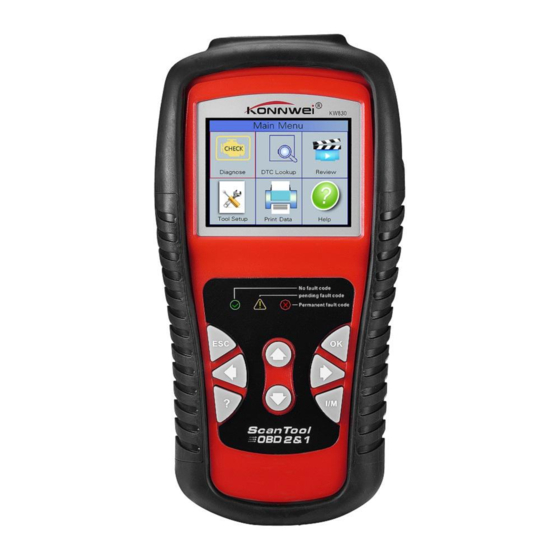
3. Using the Scan Tool 3.1 Tool Description 1) OBD II CONNECTOR – Connects the scan tool to the vehicle’s Data Link Connector (DLC)。 2) LCD DISPLAY – Displays menus and test results。 GREEN LED – Indicates that engine systems are running normally (The number of monitors on the vehicle which are active and performing their diagnostic testing is in the allowed limit,and no DTCs are present)。... - Page 13 “pending” DTC is present and/or some of the vehicle’s emission monitors have not run their diagnostic testing。 RED LED – Indicates there is a problem in one or more of the vehicle’s systems。The red LED is also used to show that DTCs are present。DTCs are shown on the Scan Tool’s emission monitors have not run their diagnostic testing。...
-
Page 14: Specifications
and upgrading。 3.2 Specifications 1) Display: TFT color display (320 x 240 dpi) 2) Operating Temperature: 0 to 60℃ (32 to 140 F°) 3) Storage Temperature: -20 to 70℃ (-4 to 158 F°) 4) External Power : 8.0 to 18.0V power provided via vehicle battery 5) Dimensions:... -
Page 15: Tool Setup
1) Connect the OBD II Cable to scan tool。 2) Find DLC on vehicle。 . A plastic DLC cover may be found for some vehicles and you need to remove it before plugging the OBDII cable. 3) plug OBD II cable to the vehicle’s DLC。 3.7 Tool Setup Use the UP/DOWN and LEFT/RIGHT scroll button to Select [Tool Setup] in the Main Menu and press OK , The screen will display the... - Page 16 press UP/DOWN key to Choose [Unit of Measure] and press OK button,the screen will display the interface as shown below: Unit Of Measure Flow: Speed: km/h Distance: Pressure1: Pressure2: Pressure3: Pressure4: Temperature: ℃ Senal: 201602001 You can press UP/DOWN key to select any option and press OK button to convert,Press ESC key to retrun。...
- Page 17 Device Self-Test Screen Test Key test LED test Senal: 201602001 A. Screen Test The Screen Test function checks if the LCD display is working normally。 1) From Tool Setup screen,use the UP/DOWN scroll button to select Tool Self-Test,and press the OK button。 2) Select Screen Test from Tool Self-Test menu and press the OK button to start test,Press ESC key to retrun。...
-
Page 18: Vehicle Coverage
2) Double press ESC to return to previous menu。 C. LED Test The LED Test Function verifies if the I/M Readiness LED indicator lamps are functioning properly。 1)When completed,Press any key to exit。 3.8 Vehicle Coverage The scan tool is specially designed to work with all OBD II compliant vehicles,including control area network (CAN),it is required by EPA that all 1996 and newer vehicles (Cars and light trucks) sold in the united states must be OBD II compliant and this includes all american,... -
Page 19: Diagnostic
CAUTION: Don’t connect or disconnect any test equipment with ignition on or engine running。 4.1 Diagnostic Use the LEFT/RIGHT button or UP/DOWN button to select [Diagnostic] in Main Menu and press OK button,the screen will display Monitor Status interface as following figure4.3: Monitor Status MIL Status DTCs in this ECU... - Page 20 Read Codes Current DTCs ($03) Pending DTCs ($07) Permanent DTCs ($0A) Record DTC 14.4V Figure 4.5 According to the above Figure to select different item by pressing UP or DOWN and press OK to confirm. Then You can usr DOW key to view the next code.
-
Page 21: Erase Codes
each codes has determined that the malfunction is no longer present and is not commanding the MIL on. Permanent codes shall be stored in non-volatile memory and may not be arased by any diagnostic services or by diasconnecting power to ECU. 4) Record DTC: Record DTC are also known as “hard codes ”... -
Page 22: I/M Readiness
Erase DTC Emission-Related Diagnostic Information has been Cleared! 14.4V Figure 4.8 Notes: Before performing this function, make sure to retrieve and record the trouble codes。 After clearing,you should retrieve trouble codes once more or turn ignition on and retrieve codes again。If there are still some trouble codes in the system,please troubleshoot the code using a factory diagnosis guide,then clear the code and recheck。... -
Page 23: Data Stream
You can use UP/DOWN button to select and press OK button,the screen will display the interface as shown below: I/M Reeadiness Misfire monitor Fuel system monitor Comprehensive component monitor Catalyst monitor Heated catalyst monitor Evaporative system monitor Secondary air system monitor Oxygen sensor monitor Oxygen sensor heater monitor EGR and/or VVT system monitor... - Page 24 AII Datastream Fuel system1 status Fuel system2 status Calculated LOAD Value 0.0% Engine Coolant Temperature 39℃ Short Term Fuel Trim - Bank 1 0.0% 1.5V Figure 4.14 You can use LEFT/RIGHT button to view other data streams。 Press ESC to return to Diagnostic Menu. Select [Select Items] in Data stream menu and press OK ,the screen will display the interface as shown below: Select Datastream...
- Page 25 Select Datastream [√] Fuel system1 status [√] Fuel system2 status [√] Calculated LOAD Value [√] Engine Coolant Temperature [√] Short Term Fuel Trim - Bank 1 1.5V Figure 4.16 After selected items and press OK, the screen will display the interface as shown below: AII Datastream Fuel system 1 status...
- Page 26 Press ESC to return to Diagnostic Menu. Select [View Graphic Items] in Data stream menu and press OK, the screen will display the interface as shown below: Select Datastream Calculated LOAD Value Engine Coolant Temperature Short Term Fuel Trim - Bank 1 Long Term Fuel Trim - Bank 1 Engine RPM 14.5V...
-
Page 27: Freeze Frame
Data Stream max 0.0 min 0.0 ■LOAD-PCT=0.0% Figure 4.19 Press ESC to return to Diagnostic Menu. You can view all data stream items or select a certain item of live data with a graph. 4.1.5 Freeze Frame When and emission-related fault occurs, certain vehicle conditions are recorded by the on-board computer. -
Page 28: O2 Sensor Test
Freeze Frame DTC that caused required freeze P0113 frame data storage Fuel system1 status Fuel system2 status Calculated LOAD Value 0.0% 96℃ Engine Coolant Temperature 14.4V Figure 4.20 You can use LEFT/RIGHT button to view the data. Press ESC to return to Diagnostic Menu. 4.1.6 O2 sensor Test The results of O2 sensor test are not live values but instead the results of the ECU’s last O2 sensor test. -
Page 29: On-Board Monitoring
Select O2 Sensor Bank1-Sensor1 Bank1-Sensor2 14.4V Figure 4.22 Press OK button, the screen will display as shown bellow: Bank1- Sensor2 Minimum sensor voltage Maximum sensor voltage 14.4V Figure 4.23 You can use UP/DOWN button to select an item and press OK , the screen will display as shown below: Minimum sensor voltage Test ID... -
Page 30: Evap System
as show below: On-Board Monitoring Test $01 Data Test $02 Data Test $04 Data Test $06 Data Test $08 Data 14.4V Figure 4.25 You can use UP/DOWN button to select an item and press OK , the screen will display as shown below: Test $01 Data $07 Component ID... -
Page 31: Vehicle Information
Evap System(mode$8) Evaporative system leak test passed 14.4V Figure 4.27 4.1.9 Vehicle Information Select [Vehicle Information] and press OK, the screen will display the information, such as VIN (Vehicle identification Number), CID (Calibration ID) and CVN (Calibration verification number), as shown below: Vehicle lnformation Vehicle ldentification Number(VIN): LFV3A24G8D3000130... -
Page 32: Review
DTC Lookup Please input DTC: P0000 The 1st range:P.C.B.U The 2nd range:0.1.2.3 The others from 0 to F Press[▲]or [ ]to change input,press[ ]or [ ]to select position, then press[ ]to confirm. Senal: 201602001 Figure 4.29 You can use UP/DOW key to change the first letter. It can be swiched among “P” , “B”... -
Page 33: Help
Tool Setup Time And Date DTC num. DTC type DTC RECORD 0 NOT SUPPORT VIN DTC RECORD 1 Pending NOT SUPPORT VIN Senal: 201602001 Figure 4.31 The recorded DTC will be displayed as shown in Figure 4.31. You can use UP/DOW key and press OK button to view detailed information. 2) Review Data stream The operation is similar to the “Review DTC”... -
Page 34: Update Mode
1. KW830 2. A PC or laptop with USB ports 3. USB cable 1) Download the programs in our website, www.konnwei.com , to be updated to your computer. 2) Run the Maxiscan in your computer.( Figure 4.34) 3) Connect the scan tool to your computer through the USB cable provided. -
Page 35: Led Interpretation
Figure 4.34 7) During the update procedure. 8) Restart the scan tool to finish the whole update. NOTE: When you made a wrong choice and the scan tool is unable to work properly, you may need to update the programs. To hole LEFT scroll button and power on the scan tool, you will enter the update mode forcedly. -
Page 36: Audio Tone Interpretation
2. A PC or laptop with USB ports 3. A USB cable 1) install Maxiscan applications through the included CD, or downloading the applications from our website: www.konnwei.com or our distributors’ site. 2) Connect the scanner to computer with the USB cable supplied. - Page 37 3) Run Maxiscan in your computer. Figure 5.1 4) Use the UP/DOWN or LEFT/RIGHT scroll button to select Print Data from Main Menu in the scan tool , and press the OK button. (Figure 5.2) Print Data Print All Print Data Stream Print Freeze Data Print DTC Senal: 201602001...
-
Page 38: Warranty And Service
1) The sole responsibility of Konnwei under the warranty is limited to either the repair or, at the option of Konnwei, replacement of the scan tool at no charge with proof of purchase, the sales receipt may be used for this purpose.
Need help?
Do you have a question about the KW830 and is the answer not in the manual?
Questions and answers