
Related Manuals for DHD Series 52


Summary of Contents for DHD Series 52
- Page 1 Series 52 52/DX Compact Mixing Console Manual © 2013 DHD Deubner Hoffmann Digital GmbH Version: 1.2.0...
-
Page 2: Table Of Contents
2 Option 2 - Both USB connected to single PC ........................... 22 3 Internal sample rate converter 10 Configuration ........................... 24 1 Program Menus File Menu ................................. New Device ..............................Open Device ..............................Save Device ..............................© 2013 DHD Deubner Hoffmann Digital GmbH... - Page 3 Series 52 - 52/DX Compact Mixing Console Manual Save Device as ..............................History ..............................Exit ..............................View Menu ................................. Maintenance Window ..............................Key Functions ..............................Logic Sources ..............................Audio Sources ..............................Watches - Logic Monitor ..............................Transfer Menu ................................. Load to Device ..............................
-
Page 4: Terms Of Use - Legal Disclaimer
52/DX Compact Mixing Console Manual © 2013 DHD Deubner Hoffmann Digital GmbH This manual is copyright of DHD. It might be distributed and copied as long as it is copied completely as a whole and this copyright notice is included. -
Page 5: About This Book
This book will provide you an overview about the applications of the 52/DX Compact Mixing Console. The content of this manual is subject to change without notice. DHD recommends to visit the DHD website once in a while to check if there is a newer version of this document available. - Page 6 Recommendations and further information are marked as notes. Sometimes you will also find off-topic content in this field, which is related to the actual topic. Tips are helpful advices, which should make work with DHD systems easier. Weblink In this fields you can find links to websites, which include for example an other manual or the possibility to download a driver for the respective DHD system.
-
Page 7: What Is New In This Version Of The Manual
Series 52 - 52/DX Compact Mixing Console Manual What is new in this version of the manual? All sections that had been added, deleted or changed are listed below. Click on the entries to reach the respective sections directly. Current version (1.2.0) (related to DXConfig, version 7.1.13):... -
Page 8: General Information
Always act according to the directions of this manual. Fix the device well in a rack or studio furniture with the mounting orientation given by DHD. Only connect the power cable of the device to a socket, which carries the voltage stated on the specification plate. - Page 9 To clean your DHD device, in general a soft, lint-free and dry cloth is sufficient. In case of severe soiling, you can use a damp cloth and household detergent.
-
Page 10: Key Features
Key Features The Series 52 Mixing Console 52/DX has been designed to be an easy-to-use tool for a broad range of TV and radio broadcasting applications. With its 4 faders and its compact table top design, it is ideal for OnAir, in the OB van, for News, Edit- and Ingest Stations. -
Page 11: Components
· highly efficient external wide-range power supply, Energy Star Level V, redundancy option · minimal system power consumption · expandable modular system allows optional integration of other DHD product lines · serial or TCP/IP interface options to radio automation or other external control systems... -
Page 12: O Modules And Connections
Components In the following table the main Features of the 52-1804 with a 52/DX control module are listed. Feature 52-1804 support for redundant power supply number of supported faders number of supported I/O boxes number of audio, power & control ports (APC) serial interface for external control TCP/IP interface for external control I/O modules and connections... -
Page 13: Xc Mic/Headphone/Gpio Module
Series 52 - 52/DX Compact Mixing Console Manual Digital outputs, AES3/EBU sample rate converter, stereo Digital outputs, S/PDIF sample rate converter, stereo Digital outputs, USB sample rate converter, stereo General purpose inputs opto coupler General purpose outputs photo mos relays... -
Page 14: Xc Digital I/O/Gpio Module
Components Weblink Please find a PDF file with pin assignments in the 52/DX list of modules on www. dhd-audio.com. 6.2.3 XC Digital I/O/GPIO module The 52-7111 XC Digital I/O/GPIO module is an input/output module with AES3/EBU-S/PDIF inputs and outputs for the 52/ DX mixing console. -
Page 15: Devicelink
Series 52 - 52/DX Compact Mixing Console Manual In the following table you can find the type and number of interfaces, which are available on each XC Analog I/O/GPIO module 52-7223: Interface type Number Specifications Line inputs 24 dBu max. - Page 16 Components The control module is tightly integrated with the control engine. It collects all events from the faders, rotary knobs and buttons and sends back the information into the status indicators and displays. To make configuration easier, the software allows to print out labels for the keys of the control module. These labels are slid under the key caps.
- Page 17 Series 52 - 52/DX Compact Mixing Console Manual The push-button caps can be removed to insert a customised label. Cap and diffuser are connected by a snap-fit on the right and on the left of the pushbutton. Grab the cap on the upper and lower side an pull it away from the black main part of the push button.
- Page 18 Components Put the diffuser on the main push-button part and push it down until the snap-fits click into their positions. Please make sure, that the snap-fits are located on the right and left hand side. Put a transparent film label (dimensions 12 mm x 12 mm) on the diffuser.
-
Page 19: 52/Dx Control Module
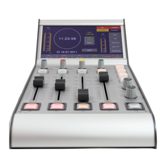
Series 52 - 52/DX Compact Mixing Console Manual 6.3.1 52/DX control module The 52/DX control module 52-1104 is a table top module including a 7" TFT Touch Display, 4 faders, push buttons, encoder and potentiometers. 1 The TFT/Touch Display shows diverse pre-set TFT pages. These pages show, for example peak meters, correlation display, clock, stopwatch and setting of EQ, dynamics unit, snapshots and other parameters. -
Page 20: Cabling
Note Breakout cables for the D-sub connectors of the 52/XS Multi-I/O Box are not available from DHD. D-Sub Pin assignment of 52-7111 Rear View 52-7111 The connectors on the rear site of the 52-7111 are D-sub type (9 pins) and provide all GPIOs for this module. -
Page 21: Sub Pin Assignment Of 52-7222 / 52-7223
Network connection To connect a PC for maintenance and configuration or the usage of DHD software together with a 52/SX console, please create a DHD exclusive network. The following drawing shows a possible 52/SX installation and it should explain the Ethernet wiring of this application. - Page 22 Example of a 52/DX installation. Connect the ETH 1 port of the 52/XS Core to the configuration PC or to the DHD Ethernet network, where the PC with the configuration software is located. To establish the connection to the office network, you should use a server PC with a second network interface card to avoid slowing down the communication in the DHD network and to block non-authorised access to the connected DHD systems.
-
Page 23: Connecting Modules To The Xs Core
Series 52 - 52/DX Compact Mixing Console Manual Connecting modules to the XS Core The control module and I/O boxes have to be connected to the APC ports of the 52/XS Core 52-1804. It is important to connect the peripheral modules to the correct APC port. -
Page 24: Usage Of Usb Audio On 52-1330
Usage of USB audio on 52-1330 Usage of USB audio on 52-1330 The 52-1330 has two USB audio ports. Each port can be used to connect a personal computer with the Multi-I/O Box of the 52/DX for input and output of a stereo signal. Connected to a PC, each USB audio port is recognised as an USB audio device, which can be used for playback and recording in every audio software. -
Page 25: Internal Sample Rate Converter
Series 52 - 52/DX Compact Mixing Console Manual A single PC connected to the 2 USB audio ports of the 52-1330. Each USB port will be identified as an "USB Audio CODEC". To use these two USB audio ports properly you should rename these two USB Audio Devices. -
Page 26: Configuration
When opening DXConfig, another software application is loaded automatically: DHD Communication Server (DHDCS). DHDCS filters TCP/IP and UDP packets from the network that are transferred to and from DHD devices and prepares them for several software applications. Please find detailed information on DHDCS in the Application Software Manual of the RM4200D. -
Page 27: Program Menus
Series 52 - 52/DX Compact Mixing Console Manual 10.1 Program Menus In this section of the manual, the menus and the commands of the DXConfig software are described. 10.1.1 File Menu 10.1.1.1 New Device A new device is created. The device contains only the default values. -
Page 28: History
Configuration 10.1.1.5 History Using the History function in the File menu of DXConfig, you can log modifications of the configuration. This way, you can later reproduce, which user made which modifications of the system at which time. Project History, logging modifications during configuration. In the File menu click History ;... -
Page 29: View Menu
10.1.2.1 Maintenance Window Using this command, you open the maintenance window. In this window, you have direct access to the modules of DHD systems, important settings and services. These functions are of a great variety and are therefore dealt with in an own chapter. -
Page 30: Audio Sources
Configuration Window Logic Sources, selecting logic sources. 10.1.2.4 Audio Sources This window shows all internal audio signals that are available for configuring the device. The audio signals are grouped according to their characteristics. Audio, selecting audio sources. On the internal TDM bus, the following audio channels are available: inputs, delays, mixing functions (sums, groups, Aux busses) pre-fader signals (fader channel after input processing), clean feeds (n-1 busses), monitor functions, fixed Version 1.2.0 - 04.02.2013 Specifications and design are subject to change without notice. -
Page 31: Watches - Logic Monitor
Series 52 - 52/DX Compact Mixing Console Manual processing, output functions, super output functions and talk outputs. You can also open this window by pressing F6 . 10.1.2.5 Watches - Logic Monitor With the Logic View window you can monitor all logics of the currently loaded DXConfig device. -
Page 32: Transfer Menu
In the DXConfig software, you can choose between different options, how the configuration PC can exchange data with the device. Select the command for up- or download. After that, the DHD Connection Dialog window opens that is identical for both commands: Version 1.2.0 - 04.02.2013... - Page 33 Fixed IP box. If the configuration PC and the devices can communicate via the UDP protocol, the list in the DHD Connection Dialog window shows all available systems. You can now select the desired destination from the list.
-
Page 34: Load To Device
This command copies the current Config from the DXConfig software to the selected device. To do this, use the command Load to Device . The DHD Connection Dialog window opens, in which you can select the desired device. (See figure DHD Connection Dialog window for connections with the device) After confirming the selection, the new Config is transferred. -
Page 35: Load From Device
Series 52 - 52/DX Compact Mixing Console Manual 10.1.3.2 Load from Device This command loads a Config from a device to the DXConfig software. In the DHD Connection Dialog window you must select the corresponding device. (See figure DHD Connection Dialog window for connections with the device) -
Page 36: Help Menu
Configuration area option description · Define here, how many backup generations shall be created. (min. Backup Levels =0, max.=100) · If this check box is selected, the software creates backups of the project file automatically. · The number of backup files can be set in the Backup Levels box. -
Page 37: Hardware
Series 52 - 52/DX Compact Mixing Console Manual 10.2 Hardware DXConfig Software - Hardware On the Hardware page you can set, which 52/DX modules are connected to your system. area option description Common settings Device name Please enter a distinctive device name for this 52/DX mixing console. -
Page 38: System Settings
Configuration 10.3 System Settings On the System Settings page, you can configure general options for your 52/DX. DXConfig Software - System Settings In the following table you can find the descriptions for these options. area option description Select here, which sample rate should be set for internal 44.1 kHz / 48 kHz synchronisation. - Page 39 Series 52 - 52/DX Compact Mixing Console Manual area option description Select the colour of the peak program meter on the TFT display. The Scale Color selected colour is used for all peak program meters of the 52/DX. Scale Type Select your preferred type of peak meter scale.
-
Page 40: O Settings
Configuration 10.4 I/O Settings On the I/O Settings page, you can configure different options for each input and output. Not all options are available for any input or output. DXConfig Software - I/O Settings In the following table you can find the descriptions for these options. area option description... - Page 41 Series 52 - 52/DX Compact Mixing Console Manual area option description Type of Shows the general signal type of the port. Signal Enter Label Enter a distinctive name for the selected input. Choose the headroom for each input from the corresponding drop-down menu. The shown Level Adjust values always refer to the devices internal default level of 0 dBint.
- Page 42 ( Off ) for this output. Dithering If you connect devices with a lower resolution of the digital signals to a DHD device, here you can define how the internal audio signal is to be dithered before leaving the digital output.
- Page 43 Series 52 - 52/DX Compact Mixing Console Manual area option description This option can adopt the values Pro (default value) or Consumer . The following parameters are changed accordingly: Mode Pro (Default) Consumer Terminator 110 Ohm 75 Ohm Output voltage...
-
Page 44: Console
Configuration area option description IOModule-X. Type of <port> Shows the general signal type of the port. Signal General Purpose Enter Label Enter a distinctive name for the selected input. Inputs (GPI) Type of Shows the general signal type of the port. Signal IOModule-X. - Page 45 Series 52 - 52/DX Compact Mixing Console Manual Element option description In this list, all available default TFT views are shown. Select a default view from the list. (For Default View differences between the default views see Default views table)
- Page 46 Configuration Monitoring key - Program: Press the Program key, to send the PGM 1 bus audio signal to the Mon1 bus. When the Program key is not active, the audio sources which is selected in the Selector view on the TFT is sent to the Mon1 bus. To set the audio source for this Mon1 bus, follow these steps: 1.
-
Page 47: Monitoring
Series 52 - 52/DX Compact Mixing Console Manual Std-CUE+Clk (without CUE peak meter) Std+Tmr Std+3PM+Tmr Std+Clk+Tmr X…the element is available in this view 10.6 Monitoring On the Monitoring page you can configure the monitoring features of the 52/DX and set up a simple talkback, for example between the control room and the studio. - Page 48 Configuration These output functions belong to the monitoring signals on this page: name on Monitoring page output function MON1 SPK Vol L MON1 SPK MON1 SPK Vol R MON1 HP Vol L MON1 HP MON1 HP Vol R MON2 SPK Vol L MON2 SPK MON2 SPK Vol R MON2 HP Vol L...
-
Page 49: Talkback
Series 52 - 52/DX Compact Mixing Console Manual 10.6.1 Talkback On the Monitoring page a talkback area with talkback specific settings is available. For each monitoring signal, you can assign 2 talkback signals. These could be microphone inputs or other audio sources. You can switch on these talkback signals by a logic source. - Page 50 Configuration Click the button, next to the Talk 1 Source box. The Audio Sources window opens. Select a audio source from the list and click assign. Talk 1 Source When the Talk 1 Condition logic becomes true, the Talk 1 Source is active on the corresponding bus.
-
Page 51: On-Air Switch
Series 52 - 52/DX Compact Mixing Console Manual column description Select this check box to add a bus to source list 2. This bus will be available for Add to Selector List 2 monitoring in the Monitor 2 list, which is available in the Selector view of the TFT/Touch Display. - Page 52 Configuration On-Air Switch configuration To configure the On-Air switch, follow these steps: 1. Click the -button next to the Source 1L box, the Audio Sources window opens. 2. In the Audio Sources window, select a source and click Assign . Alternatively you can double-click on the source or drag it to the Source box.
-
Page 53: Users
Series 52 - 52/DX Compact Mixing Console Manual 10.9 Users On the Users page you can you can create users with different access rights. DXConfig Software - Users You can create users with different access rights by assigning them to the preconfigured user groups. To do this, follow these steps: 1. -
Page 54: Authorisation
Configuration 10.10 Authorisation On the Authorisation page you can assign access rights for different preconfigured user groups. DXConfig Software - Authorisation To assign access rights to authorisation groups, follow these steps: 1. In the Group Name list, select a authorisation group. 2. -
Page 55: Index
I/Os Digital Out Mode digital outputs APC ports digital signal processing assignment of the control modules Audio Sources DIM MON1/2 SPK Authorisation display Autolock Dithering download DSub type D-sub type 17, 18 © 2013 DHD Deubner Hoffmann Digital GmbH... - Page 56 9, 10 monitor selector Hardware page monitoring headphone outputs 9, 10 mono Headroom multichannel audio connection Help Menu Multi-I/O Box History MUTE Mute Logic I/O boxes I/O connections New Device I/O Settings © 2013 DHD Deubner Hoffmann Digital GmbH...
- Page 57 TFT Touch display TFT view TFT/Touch Display TFT/Touch displays timer real-time operation Red Bar Over Toolbox5 touch Transfer Menu sample rate Save Device Save Device as upload Scale Color USB audio Scale Type user group © 2013 DHD Deubner Hoffmann Digital GmbH...
- Page 58 Index users view View Menu Watches - Logic Monitor Windows 7 Windows Vista XS Core 8, 34 XS Multi-I/O Box Zero Offset © 2013 DHD Deubner Hoffmann Digital GmbH...
Need help?
Do you have a question about the Series 52 and is the answer not in the manual?
Questions and answers