Table of Contents
Advertisement
Advertisement
Table of Contents

Related Manuals for Chamberlain CAPXL


Summary of Contents for Chamberlain CAPXL
- Page 1 LiftMaster Cloud™ Connected Access Portal - High Capacity INSTALLATION MANUAL...
- Page 2 To protect against fire and electrocution: • Disconnect power at the fuse box BEFORE proceeding. • Disconnect power BEFORE installing or servicing CAPXL. • To AVOID damaging gas, power or other underground utility • NEVER connect a keypad/reader or lock to doors without first lines, contact underground utility locating companies BEFORE consulting the applicable fire code.
-
Page 3: Table Of Contents
Internet Service ............10 Phone Provider ............10 Setup a LiftMaster Cloud Account ....... 10 INSTALL Remove Knockouts ............. 11 Mount the CAPXL ............12 Install Antennas............13 Install the Ground............14 Connect Power ............15 NETWORK Connect Internet ............16 Validate Setup ............. -
Page 4: Capxl Overview
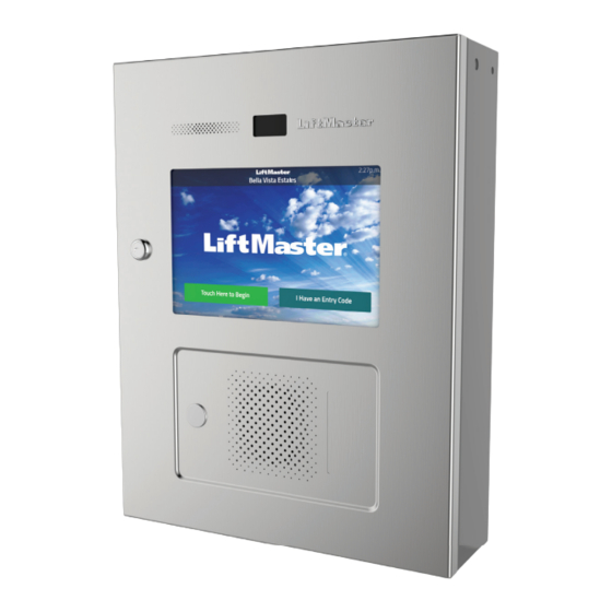
INTRODUCTION PRE-INSTALL INSTALL NETWORK ACCESS CONTROL CAPXL Overview CAMERA WINDOW MICROPHONE DISPLAY (TOUCHSCREEN) LOCK PROXIMITY READER LOCATION POSTAL LOCK SPEAKER LOCATION Wi-Fi ® ANTENNA SENSOR BOARD ® Security+ 2.0 CAMERA MOUNTING BRACKET POWER/INTERNET BOARD RADIO ANTENNA RADIO ANTENNA Wi-Fi ®... -
Page 5: Power/Internet Board Overview
INTRODUCTION PRE-INSTALL INSTALL NETWORK ACCESS CONTROL Power/Internet Board Overview Speaker Audio Postal Lock Sensor Board Display Backlight Display (Touch) Dip Switches Power Connection (Switch #1 is used to for Control Board toggle Admin Mode) LOOP BOARD Door Board 2 RADIO ANTENNA POWER Door Board 1 ETHERNET... -
Page 6: Door Board Overview
PRE-INSTALL INSTALL NETWORK ACCESS CONTROL Door Board Overview The CAPXL has a combination of access control inputs/outputs on the Door Boards that work in conjunction to control up to 4 access points. DOOR BOARD 1 DOOR BOARD 2 Door 1... -
Page 7: Carton Inventory
INTRODUCTION PRE-INSTALL INSTALL NETWORK ACCESS CONTROL Carton Inventory CAPXL Goose-neck Gasket Power Supply ® Radio Antenna (Security+ 2.0 and Cable Keys (2) S10K30MOV (Metal Oxide Varistor)(4) 1N4005 Diode Kit (4) Wi-Fi ® Antenna and Cable Ferrite Core PROVIDED (NOT SHOWN) •... -
Page 8: Dimensions
Operating Current 1.25 Amps - Without Accessories Surge Suppression EFT: 2 kV Power Line, ESD: 15 kV HBM / 8 kV Direct / 200V MM CAPXL Operating Temperature Range - 29°C to 54°C (-20°F to 130°F) Enclosure Stainless Steel Storage and Shipping Temperature Range -40°C To 65°C (-40°F to 149°F) -
Page 9: Wire Specifi Cations
Local Area Network (LAN) 8-Conductor, 24 AWG Twisted pair 328 feet* (100 m) CAT 5 or better Network Cable Grounding the Chassis (use grounding lug in CAPXL) 12 AWG Copper 12 feet (3.7 m) Door Strike 2-Conductor 18-22 AWG Shielded 100 - 250 feet (30.5 - 76.2 m) -
Page 10: Internet Service
Phone Service A subscription with a SIP provider is required for the CAPXL to make phone calls. Phone.com is the preferred SIP provider and the only provider LiftMaster certifi es calling performance. Sign up through LiftMaster Cloud after a CAPXL is added to a Facility. -
Page 11: Remove Knockouts
• BEFORE opening the front cover of the CAPXL, remove ANY table as shown. accumulated water from the top of the CAPXL. -
Page 12: Mount The Capxl
Attach the goose-neck gasket (provided) if mounting to a goose-neck. prevent damage to the CAPXL from moisture. 2. Mount the CAPXL securely to a fl at surface or pedestal with appropriate hardware taking care to route wiring through appropriate knockouts. Stainless steel hardware is recommended to mount the CAPXL. -
Page 13: Install Antennas
Wi-Fi ® antennas must be a minimum of 8 inches (20 cm) apart. Install the antennas on opposite sides of the CAPXL. Optional antenna cable kits are available for remote antenna mounting (refer to accessories). ® Security+ 2.0 Radio Antenna (if applicable) Used with LiftMaster Passport Security+ 2.0... -
Page 14: Install The Ground
IMPORTANT: An earth ground rod is strongly recommended and should be no To AVOID damaging gas, power or further than 12 feet (3.7 m) from the CAPXL and use a minimum of 12 gauge other underground utility lines, contact underground utility locating wire in most cases. -
Page 15: Connect Power
NETWORK ACCESS CONTROL Connect Power The outlet for the CAPXL MUST be an external dedicated 120 Vac outlet. • DO NOT use ANY power supply other Refer to the table below for maximum wire run distances. This outlet should than those supplied with your CAPXL. -
Page 16: Connect Internet
Wired Connection The Local Area Network (LAN) port is a 10/100/1000 Ethernet interface with an RJ45 jack for connecting the CAPXL to a hub, switch, or router in order for it to gain connectivity to the Internet. Use a straight, (i.e., non-crossover) Cat5, Cat5e, or Cat6 cable to connect to a local hub, switch or router. -
Page 17: Gate Access (Wired)
Isolation or equivalent LINE Relay Use 18-22 AWG NORMALLY CLOSED NOTE: DO NOT run high voltage power within the CAPXL COMMON enclosure. ALARM BYPASS Power for Maglock COMMON (Not Provided) For DC Power: DO NOT use the power NORMALLY OPEN... -
Page 18: Gate Access (Wireless)
(email notifi cations are confi gured in LiftMaster Cloud). Up to 8 gate operators can be paired with the CAPXL - one for each primary and auxiliary relay. If using dual gates, program the CAPXL to the primary operator. -
Page 19: Door Access
Isolation LINE or equivalent Relay NOTE: DO NOT Use 18-22 AWG NORMALLY CLOSED run high voltage power within the CAPXL COMMON enclosure. ALARM BYPASS Power for Maglock COMMON (Not Provided) For DC Power: DO NOT use the power NORMALLY OPEN... -
Page 20: Card Reader
NETWORK ACCESS CONTROL Card Reader The CAPXL is designed specifi cally for the LMMC-MINI reader to be mounted on the faceplate. 1. Disconnect power from the CAPXL. 2. Remove and discard the wing nuts and reader cover from the CAPXL. -
Page 21: Wiegand Output
Disconnect power BEFORE making electrical connections. The CAPXL offers a Wiegand output capable of 26 bit transmission of the following data: • Success Call with access granted by the resident. The CAPXL will provide a LiftMaster Cloud specifi ed facility code followed by the Directory Code of the resident that granted access. And/Or •... -
Page 22: Postal Lock
INTRODUCTION PRE-INSTALL INSTALL NETWORK ACCESS CONTROL Postal Lock 1. Remove the wing nut and plug. Discard the wing nut and plug. 2. Remove 4 mounting nuts from studs. 3. Install postal lock using 4 nuts from step 2. 4. Cut the factory installed wire tie from the postal lock switch. The postal lock switch is wired from the factory. -
Page 23: Auto-Call Feature
Not supported automatically dialed. AUXILIARY 1. Secure the Loop Detector Board (model LPEXP) to the standoffs in the CAPXL with the provided screws. 2. Connect the wire harness from the Loop Detector Board to the Power/Internet Board. 3. Connect the loop wires to the input on the Loop Detector Board. -
Page 24: Wiring Diagram
Wiring Diagram Not responsible for conflicts between the information listed in the wiring diagram and the requirements of your local building codes. The information is for suggested use ONLY. Check your local codes BEFORE installation. orange blue white MICROPHONE 1 - Red black 2 - Orange 3 - Yellow... -
Page 25: Repair Parts
Repair Parts ITEM PART NUMBER Cam And Lock Kit K002B0799-3 Power Supply K002A1978 Wi-Fi ® Antenna Kit K76-38957 Radio Antenna Kit K76-38958 Faceplate Kit K76-38327 Sensor Board K001D8592 Camera Window And Gasket K41-38476 Touchscreen Display K002C1904 Control Board K002C1905 Power/Internet Board K001D8439 Door Board And Covers K001D8478... -
Page 26: Confi Guration Sheet
Confi guration Sheet Record device information and confi guration settings below. CAPXL Name: NOTE: Any user of the system is subject to the terms outlined in the product EULA. Notes: DEVICE CONFIGURATION: DOOR 1 DOOR/GATE NAME: WIEGAND STATUS INPUTS EOL (Y / N) -
Page 27: Legal Disclaimers
Consult the dealer for help. Canada-Underwriters Laboratories Compliancy The CAPXL shall be installed in accordance with Part 1 of the Canadian Electrical Code. Documentation Disclaimer and Restrictions Information in this document is subject to change without notice and does not represent a commitment on the part of LiftMaster. For the most up-to-date information, visit LiftMaster.com. -
Page 28: Warranty
Warranty LiftMaster (“Seller”) warrants to the fi rst purchaser of this product, for the structure in which this product is originally installed, that it is free from defect in materials and/or workmanship for a period of two years from the date of purchase. The proper operation of this product is dependent on your compliance with the instructions regarding installation, operation, maintenance and testing.
Need help?
Do you have a question about the CAPXL and is the answer not in the manual?
Questions and answers