Table of Contents
Advertisement
Indoor Mobility Point™
Quick Start Guide
Trapeze Networks, Inc.
5753 W. Las Positas Blvd.
Pleasanton, CA 94588
Tel: +1 925-474-2200
Fax: +1 925-251-0642
Toll-Free: 877-FLY-TRPZ (877-359-8779)
For the most current version of all documentation, go to
www.trapezenetworks.com
Part Number: 730-9502-0242 Rev. H
Advertisement
Table of Contents

Related Manuals for Trapeze MP-82

Summary of Contents for Trapeze MP-82
-
Page 1: Quick Start Guide
Indoor Mobility Point™ Quick Start Guide Trapeze Networks, Inc. For the most current version of all documentation, go to 5753 W. Las Positas Blvd. www.trapezenetworks.com Pleasanton, CA 94588 Tel: +1 925-474-2200 Fax: +1 925-251-0642 Toll-Free: 877-FLY-TRPZ (877-359-8779) Part Number: 730-9502-0242 Rev. H... - Page 2 Trapeze Networks This document provides basic hardware installation instructions for indoor MP Access Point models. Warning! Installation must be performed by qualified service personnel only. Read and follow all warning notices and instructions marked on the product or included in the documentation.
- Page 3 Trapeze Networks Varning! Installation får endast utföras av kvalificerad servicepersonal. Läs och följ alla varningsmeddelanden och instruktioner markerade på produkten eller inkluderade i dokumenteringen. Innan produkten installeras skall resten av dessa dokument läsas. Warning! Advarsel! Installation må kun gennemføres af faglært servicepersonale. Læs, og følg alle de advarselsmeddelelser og anvisninger, der er anført på...
- Page 4 Warning! Warning! Warning! Warning! Operation of the MP-82 with the PowerDsine PD-7001G PoE injector is subject to Class A emissions restrictions. Please consult the Trapeze Networks Regulatory Guide Note: for more complete details and suggestions. Indoor Mobility Point™ Quick Start Guide...
-
Page 5: Package Contents
For more information about MP installation as well as safety and installation requirements, see the following: Trapeze Indoor Mobility Point Installation Guide ❑ For detailed compliance information see the Trapeze Regulatory Guide located at: ❑ http://www.trapezenetworks.com/support/contact_support/. The guide can be downloaded in PDF format. - Page 6 Trapeze Networks MP-422/432/522 Package Contents The shipping carton for an MP contains the following items: 1. One MP 2. Mounting kit including: One mounting bracket (attached to the MP) ❑ The MP-522 package contains a specific mounting bracket (attached to the MP) One paper mounting template (used for marking cutting areas and screw holes) ❑...
-
Page 7: Fcc Caution
Four ANT-7360P-IN antennas T-bar clamps The Trapeze-approved antennas listed in the table below can also be used with the MP-522E. FCC Caution To reduce potential radio interference to other users, the antenna type and its gain should be so chosen that the equivalent isotropically radiated power (e.i.r.p) is not more Warning! than that permitted for successful communication. -
Page 8: Installation Requirements And Recommendations
If you are using RingMaster to plan your Trapeze Networks Mobility System installation, you might want to create and verify a network plan for the entire Trapeze Network installation and generate an MP work order before installing MPs. A network plan and the MP work orders generated from it... -
Page 9: Wall Installation Recommendations
Trapeze Networks MX Recommendation Trapeze Networks recommends that you install and configure the MX before installing an MP. If the MX is already installed and configured for the MP, you can immediately verify the cable connection(s) when you plug the cable(s) into the MP. - Page 10 Trapeze Networks This device complies with Part 15 of the FCC Rules. Operation is subject to the following two conditions: (1) This device may not cause harmful interference, and (2) this device must accept any interference received, including interference that may cause undesired operation.
-
Page 11: Additional Radio Safety Advisories
Cet appareil numérique de la classe B est conforme á la norme NMB-003 du Canada. Additional Radio Safety Advisories For translations of warnings, see the TrapezeRegulatory Guide. The Trapeze Regulatory Guide is located at http://www.trapezenetworks.com/support/contact_support/ and can be downloaded in PDF format. -
Page 12: Cabling Requirements
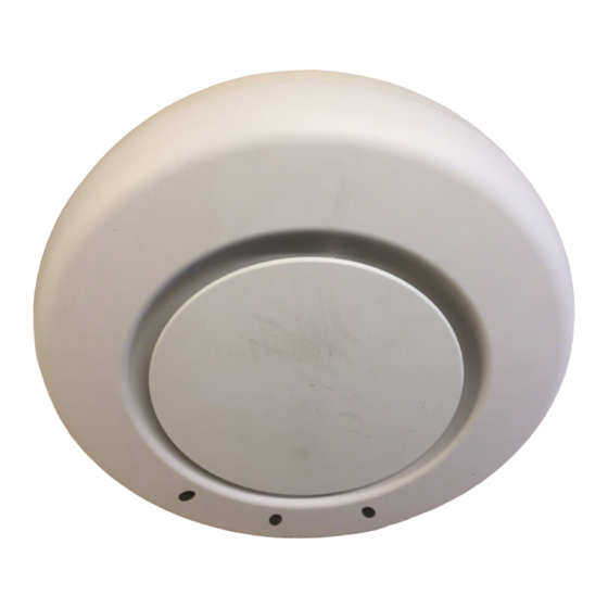
Warning! The MP is intended for indoor use only. Do not install the device outdoors, unless you install it with a Trapeze Networks outdoor MP enclosure. Note: To reduce the possibility of connection interference caused by dust, clean the Cat 5 connector pins before inserting a cable into an MP. - Page 13 Note: MP-82 Ceiling Mount Instructions Suspended Ceiling Installation — Flush Ceiling Tiles MP-82 1. Select an installation location centered over a T-bar in the ceiling. 2. Cut a hole as follows in the ceiling tile for the Cat 5 cable: a.
- Page 14 Trapeze Networks If the T-bar width is 14.2 millimeter (9/16 inches), you need to install the 14.2-millimeter (9/ ❑ 16 inches) T-bar clamp. Go to step 4. If the T-bar width is 23.9 millimeter (15/16 inches), the universal mounting bracket fits ❑...
- Page 15 Pull on the lock to verify that it is secured to the MP. f. Remove the key. 9. Unlock the MP-82 by inserting the lock/unlock tool into the Unlock hole and push until you feel the internal bracket slide across.
- Page 16 Trapeze Networks 10. Lift the MP into place on the universal mounting bracket as shown below. Make sure the cable feeds properly into the ceiling as you lift the device, and does not become trapped between the MP and the bracket.
-
Page 17: Wall Mount Installation
3. Unlock the MP by inserting the lock/unlock tool into the Unlock hole and push until you feel the internal bracket slide across. 4. Mount the MP-82 onto the mounting bracket. 5. Lock the MP onto the bracket by inserting the lock/unlock tool into the Lock hole on the MP and... - Page 18 Trapeze Networks Figure 1–5. Step 4—Installing a T-bar Clamp T-bar Slide together T-bar clamp halves 5. Unlock the universal mounting bracket from the MP by inserting the lock/unlock tool into the Unlock hole on the MP as shown in Figure 1–6 below.
- Page 19 Trapeze Networks 7. Install the universal mounting bracket as follows onto the T-bar or T-bar clamp. a. As shown in Figure 1–8 below, place the universal mounting bracket against the T-bar or clamp so that the two screw holes face downward and the two T-bar flanges face upward and are adjacent to the T-bar edges.
- Page 20 Trapeze Networks MP-522-Specific Optional Earthquake Safety Step Note: At this point, once you have the T-bar installed and the universal mounting bracket snapped into place, you have the option of securing the bracket for earthquake safety using the two supplied M3 pan head threaded screws.
- Page 21 Trapeze Networks a. Loop the Kensington lock cable around an object that cannot be moved or damaged by a person pulling on the cable. b. Insert the key into the Kensington lock. c. Insert the Kensington lock into the security slot on the MP.
-
Page 22: Suspended Ceiling Installation-Drop Ceiling Tiles
Trapeze Networks 12. Lock the MP onto the bracket by inserting a small-pointed instrument or a paperclip into the Lock hole on the MP as shown in Figure 1–11 below. To prevent possible damage to the MP, make sure the device is fully locked onto the bracket before releasing it. - Page 23 Trapeze Networks Figure 1–12 shows an example for a 23.9-millimeter (15/16-inch) T-bar. Figure 1–13 shows an example for a 15.9-millimeter (5/8-inch) T-bar. Figure 1–12. Step 3—Installing the T-bar Clamp for a 23.9-millimeter (15/16-inch) T-bar T-bar Slide together T-bar clamp halves Figure 1–13.
- Page 24 Trapeze Networks Figure 1–14. Step 4—Unlocking the Bracket 5. Remove the bracket as shown in Figure 1–15 below. Figure 1–15. Step 5—Removing the Bracket 6. Install the universal mounting bracket as follows onto the T-bar clamp: a. As shown in Figure 1–16, place the universal mounting bracket against the T-bar clamp so that the two screw holes face downward and the two T-bar flanges face upward and are adjacent to the T-bar edges.
- Page 25 Trapeze Networks Figure 1–16. Step 6—Top View Universal mounting bracket T- bar T-bar clamps (attached to T-bar) Port connector opening (Viewed from above ceiling tiles, looking down.) Figure 1–17. Step 6—Bottom View Port connector Universal mounting bracket opening T-bar 7. Pull the Cat 5 cable about 15 centimeters (about 6 inches) out of the hole in the ceiling tile and through the port connector opening to create enough slack to insert the cable.
- Page 26 Trapeze Networks Figure 1–18. Step 9—Placing the MP on the Bracket 11. Lock the MP onto the bracket by inserting a small-pointed instrument or a paperclip into the Lock hole on the MP as shown in Figure 1–19 below. To prevent possible damage to the MP, make sure the device is fully locked onto the bracket before releasing it.
-
Page 27: Junction Box Installation
Trapeze Networks Junction Box Installation 1. Unlock the universal mounting bracket from the MP by inserting a small-pointed instrument or a paperclip into the Unlock hole on the MP as shown in Figure 1–20. Use a lock/unlock tool to unlock the MP. Do not use a screwdriver because it may cause damage to the MP lock mechanism or electronic components. - Page 28 Trapeze Networks Figure 1–22. Step 3—Placing the Bracket on the Junction Box Junction box Port connector opening 4. Pull the Cat 5 cable about 15 centimeters (about 6 inches) out of the junction box and through the port connector opening to create enough slack to insert the cable into the port connectors.
-
Page 29: Solid Wall Or Ceiling Installation
Trapeze Networks Figure 1–23. Step 7—Locking the Bracket Lock 9. To ensure that the MP is fully locked onto the bracket, gently pull down on the MP and attempt to rotate it from side to side. If the MP comes off the bracket, relock the device onto the bracket as described in step 8. - Page 30 Trapeze Networks 2. Install the drywall anchor(s): a. Hammer a drywall anchor into each hole, up to the beginning of the threads on the anchor. b. Screw each anchor the rest of the way into the hole using a #2 Phillips-head screwdriver.
- Page 31 Trapeze Networks 6. Insert the #6 sheet metal screws into the screw holes, and tighten them to secure the universal mounting bracket to the wall or ceiling. (If you routed the Cat 5 cable through a hole in the wall or ceiling, insert the screw into the center screw hole only.)
- Page 32 Trapeze Networks 9. As shown in Figure 1–27, place the MP on the bracket, making sure to remove any slack that occurs in the cable between the bracket and the MP. Figure 1–27. Step 8—Cable Placement Cable Universal mounting bracket 10.
- Page 33 Trapeze Networks If the MP comes off the bracket, relock the device onto the bracket as described in step 10 on page 32. 12. If the MP requires an external antenna, install and connect the antenna. Tabletop Installation 1. Reverse the universal mounting bracket: a.
- Page 34 Trapeze Networks c. Turn over the universal mounting bracket, then align the bracket over the cable ports and the four mounting posts as shown in Figure 1–31 below. Figure 1–31. Step 1c—Turning Over the Bracket d. Once the bracket is fully seated, lock the bracket onto the MP by inserting the lock/unlock tool into the Lock hole on the MP as shown in below.
-
Page 35: Connecting An Mp To An External Antenna
5. If the MP requires an external antenna, install and connect the antenna. Connecting an MP to an External Antenna Each radio in an Indoor MP can use an optional Trapeze external antenna. To mount the antenna, see the instructions that come with the antenna. -
Page 36: Installing An Indoor Mp-522E
Trapeze Networks Installing an Indoor MP-522E The MP-522E installation steps for ceiling or wall mount are the same as the MP-422/432/522 except that you must install and orient the four antennas on the MP before supplying power to the unit. The MP-522E has no internal antennas and requires antennas for all types of operation.Once the MP is... -
Page 37: Mp-522E Installation Antenna Orientation
Trapeze Networks MP-522E Installation Antenna Orientation Adjust the MP-522E antennas as shown below for optimal polarization. Always turn the paddle antenna clockwise while adjusting the antenna orientation in order to prevent loosening of the connector. Warning! Wall Mount Radio port 3... -
Page 38: Connecting An Mp To An Mx
“Configuring MP Access Points” chapter in the Trapeze Mobility System Software Configuration ❑ Guide External Antenna Connectors The Indoor MPs (except for the MP-82 and MP-432) have connectors for attaching optional external antennas. Table 1– 3 below lists the Trapeze-supported external antenna models. - Page 39 The Indoor MP radios are certified for use only with these external antennas. Note: © 2010 Trapeze Networks, Inc. All rights reserved. Trapeze Networks, the Trapeze Networks logo design, Trapeze Smart Mobile, Trapeze Networks Mobility System Software, RingMaster, Mobility System, Mobility Exchange, Mobility Point, SafetyNet, MX, and MP are registered trademarks and/or registered service marks of Trapeze Networks, Inc.
Need help?
Do you have a question about the MP-82 and is the answer not in the manual?
Questions and answers