Table of Contents
Advertisement
Quick Links
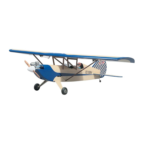
Wing Span - 59.5 in [1510mm]
Wing Area - 809 sq in [52.2 sq dm]
Weight - 5 lb 12 oz [2610 g]
Wing Loading - 16.4 oz/sq ft [50 g/sq dm]
Fuse Length - 47 in [1195mm]
WARRANTY
Great Planes
Model Manufacturing Co. guarantees this kit to
®
be free from defects in both material and workmanship at the
date of purchase. This warranty does not cover any component
parts damaged by use or modi cation. In no case shall Great
Planes' liability exceed the original cost of the purchased kit.
Further, Great Planes reserves the right to change or modify this
warranty without notice.
In that Great Planes has no control over the nal assembly or
material used for nal assembly, no liability shall be assumed nor
accepted for any damage resulting from the use by the user of
the
nal user-assembled product. By the act of using the
user-assembled product, the user accepts all resulting liability.
If the buyer is not prepared to accept the liability associated
with the use of this product, the buyer is advised to return
READ THROUGH THIS MANUAL BEFORE STARTING CONSTRUCTION. IT CONTAINS IMPORTANT
INSTRUCTIONS AND WARNINGS CONCERNING THE ASSEMBLY AND USE OF THIS MODEL.
© 2017 Great Planes Model Mfg. A subsidiary of Hobbico,
INSTRUCTION MANUAL
Inc.
®
this kit immediately in new and unused condition to the
place of purchase.
To make a warranty claim send the defective part or item to
Hobby Services at the address below:
Hobby Services
3002 N. Apollo Dr. Suite 1
Champaign IL 61822 USA
Include a letter stating your name, return shipping address, as
much contact information as possible (daytime telephone
number, fax number, e-mail address), a detailed description of
the problem and a photocopy of the purchase receipt. Upon
receipt of the package the problem will be evaluated as quickly
as possible.
(217) 398-8970, Ext 5
airsupport@greatplanes.com
™
Champaign, Illinois
GPMA0493
Advertisement
Table of Contents

Subscribe to Our Youtube Channel
Related Manuals for GREAT PLANES Pete'n Poke Sport 40


Summary of Contents for GREAT PLANES Pete'n Poke Sport 40
-
Page 1: Instruction Manual
3002 N. Apollo Dr. Suite 1 Champaign IL 61822 USA In that Great Planes has no control over the nal assembly or material used for nal assembly, no liability shall be assumed nor Include a letter stating your name, return shipping address, as... -
Page 2: Table Of Contents
TABLE OF CONTENTS INTRODUCTION INTRODUCTION ..................2 PRECAUTIONS ..................2 Congratulations and thank you for purchasing the Great ADDITIONAL ITEMS REQUIRED.............3 Planes Pete ‘n Poke Sport 40. The Pete ‘n Poke is the third Hardware and Accessories..............3 Adhesives and Building Supplies ............3 in a series of nostalgic-looking sport models from Great Optional Supplies and Tools ..............3 Planes that are intended to be simple to build and relaxing... -
Page 3: Additional Items Required
Medium T-pins ❏ programs and instructors are available at AMA club sites to Great Planes Plan Protector (GPMR6167) or wax paper ❏ help you get started the right way. Contact the AMA at the Drill bits: 1/16", 3/32", 1/8", 9/64" (or 1/8"), #8 (or address or toll-free phone number below: 3/16"), 3/16", 1/4"... -
Page 4: Important Building Notes
A flat, durable, easy to handle sanding tool is a necessity for instructions will make a recommendation. building a well finished model. Great Planes makes a complete range of Easy-Touch Bar Sanders (patented) and replaceable Easy-Touch Adhesive-backed Sandpaper. While building the •... -
Page 5: Types Of Wood
their die sheets now or wait until you need them. If a part is Types of Wood difficult to remove, don’t force it out but cut around it with a hobby knife and a #11 blade. After you remove the parts from their die sheets, lightly sand the edges to remove slivers or die-cutting irregularities. -
Page 6: Die-Cut Patterns
DIE-CUT PATTERNS... -
Page 7: Die-Cut Patterns
DIE-CUT PATTERNS... -
Page 8: Build The Tail Surfaces
Build the Fin & Rudder ❏ 1. Place the fin portion of the fuse plan over your flat building board. Cover the plan with Great Planes Plan Protector. ❏ 4. Cover the rudder portion of the plan with Plan Protector. Building over the plan, glue together the die-cut 1/8"... -
Page 9: Hinge The Tail Surfaces
❏ 5. Remove the stab from the plan. Trim the center of the 2. Use a Great Planes Precision Center Marking Tool LE as shown on the plan, then sand both sides of the (GPMR4005) to make a centerline on the TE of the fin and stab flat. - Page 10 CA hinge strip. Snip the corners off so they go in easier. ❏ 3. If you have a Great Planes Slot Machine hinge slotting tool, cut the hinge slots in all of the tail surfaces. If you do not have a Slot Machine, cut the hinge slots as described below: ❏...
-
Page 11: Build The Wing
8-3/4" x 16" skin for the bottom center- section sheeting. ❏ 8. Cut a 1/8" groove in the leading edge of both elevators to accommodate the wire. Hint: Use a Great Planes Groove Tube ™ Cutting Tool (GPMR8140) or a 1/8" brass tube sharpened on one end to cut the grooves. - Page 12 Refer to this photo for the following two steps. front edge of the skin where indicated by the arrows on the plan. Pin the skin into position. ❏ 9. Add the top center aft spar and the die-cut 1/8" plywood aft wing bolt plate to the ribs.
- Page 13 Refer to this photo for the following three steps. ❏ 14. Remove the center-section from the plan. Use a bar sander with 80-grit sandpaper to sand the bottom sheeting ❏ and the trailing edge block even with the outer ribs. 19.
-
Page 14: Finish The Center-Section
How to drill perpendicular holes. ❏ 2. Use thick CA or Great Planes Pro Wood Glue to glue To be certain the holes are perpendicular to the bottom the top center-section sheeting into position. -
Page 15: Build The Outer Panels
❏ ❏ 7. Pin one of the 1/4" x 1/4" x 27-1/2" aft spars (leftover Build the Outer Panels from the center-section) over its location on the plan. The same as the bottom main spar, the root end of the aft spar Build the right wing panel first, so you can follow the photos aligns with the root of the bottom LE sheet and the tip of the the first time through. - Page 16 ❏ ❏ ❏ ❏ 13. Make the tip reinforcement for rib W6 where shown 18. Use the remainder of the 1/16" x 3/4" balsa stick on the plan from leftover 1/8" plywood, then glue it into you used for the center-section sub leading edge as the sub position.
-
Page 17: Join The Wing Panels
Refer to this photo for the following four steps. ❏ ❏ 1. Place the right wing panel plan over your building board and cover the aileron plan with Great Planes Plan Protector. Align the right wing panel with the plan and pin it into position. -
Page 18: Hook Up The Ailerons
❏ ❏ 4. Use thin or medium CA to glue the aileron base to the aileron LE. Glue four die-cut 1/8" balsa aileron ribs W7 to the aileron base and the aileron LE. ❏ ❏ 2. Glue two leftover 1/4" x 1/2" balsa sticks to the outer and aft edge of the servo tray. -
Page 19: Finish The Wing
❏ 2. Glue the die-cut 1/8" plywood wing strut support to the forward support and the side support, then glue the die-cut 3/32" balsa aft support into position as shown. ❏ 3. Cut a hole in the bottom wing sheeting that will not interfere with the main wing struts, then use the string you built into the wing to route the servo wires through the hole and out to the servos. -
Page 20: Frame The Bottom Of The Fuselage
❏ 2. Without using any glue, join both fuselage sides to the is over your building board and cover it with Great Planes fuse top and the formers. Hold the fuselage sides in position Plan Protector. Pin the forward fuse top over its location on with T-pins and clamps. - Page 21 ❏ 9. Remove the fuse from the building board. Referring to the photo and the fuse plan for the correct orientation, use 30-minute epoxy to glue all four strut reinforcements into position. The dashed lines on the reinforcement plates indicate the position of the reinforcements behind them. Immediately proceed to the following step.
- Page 22 mount. Cut the servo hatch mount from another leftover 1/2" x 3/8" balsa stick and glue it across the front of former F3. Cut a 1/8" x 1/4" stick to the correct length from leftover 1/8" plywood and glue it across the back of the landing gear mount between the fuse sides.
-
Page 23: Join The Fin To The Fuselage
Refer to the sketch and these photos for the following three steps. ❏ 22. Sand the pushrod guide tubes even with the fuse sides. Join the Fin to the Fuselage ❏ 1. If you haven’t done so already, final-sand the fin and stab. ❏... -
Page 24: Frame The Top Of The Fuselage
string and align the arrow with one end of the stab as shown in the photo. Swing the string over to the same position on the other end of the stab. While keeping the TE of the stab centered in the fuse, adjust the stab and slide the tape along the string until the arrow aligns with both sides of the stab. -
Page 25: Make The Main Wing Struts
❏ Refer to this photo while gluing in the turtle deck 7. Sand the front of the stringers even with former F-6B. stringers. Glue together both halves of the die-cut 3/32" balsa former F6-A. Glue F6-A into position. Refer to this photo for the following three steps. ❏... - Page 26 ❏ 8. Remove the guide from the strut, then cut it into two 7/8" pieces. ❏ 4. Separate the struts. Use cigarette lighter fuel or other solvent to remove the template and wash the spray adhesive Refer to this photo for the following three steps. from the struts.
-
Page 27: Mount The Engine
Notch the cockpit floor as necessary. ❏ 3. Use a Great Planes Dead Center Hole Locator (GPMR8130) or something similar to mark the location of the mounting holes onto the engine mount. -
Page 28: Connect The Pushrods
❏ ❏ 7. Drill 1/4" holes through former F1-A to pass the fuel 4. The same way you did the ailerons, connect the lines. Temporarily connect the fuel lines to the tank and route elevator and rudder to the servos using the pushrods and them through the former to make sure the holes are in the hardware shown on the plan. -
Page 29: Mount The Landing Gear
gluing the first sheet into position, use it as a pattern to make the second sheet. Wet the outside of the sheets with window cleaner to help them bend easier. ❏ 3. Use the cockpit sheeting template on the plan to make the two cockpit sheets from the remaining 3/32"... -
Page 30: Join The Main Wing Struts
❏ in the straps will be centered over the outer ply pieces. It 9. Remove the engine. Use epoxy or fuelproof paint to may be necessary to trim part of the bottom sheeting to coat the engine compartment under the engine mount. Be accommodate the straps. - Page 31 8. Use 30-minute epoxy to glue the front and rear supports trimming both sides equally at the bottom until the wing to the struts. For additional strength, add Great Planes incidence is one degree. Note: A 1/16" change in the length...
- Page 32 of the struts equals an approximately one degree change in incidence. ❏ 12. Mark the exact center of the aft support where the wing bolt hole will be drilled. ❏ 16. Once you have achieved the correct alignment, hold the wing in position and drill #7 holes through the forward supports using the holes in the wing as a guide.
-
Page 33: Final Construction
FINAL CONSTRUCTION Build the Static Wing Struts ❏ ❏ 4. Fit the top of the static strut into the wing strut support in the right wing, then fit the bottom of the static strut into the fuse as you bolt the wing into position. See if the static struts are at correct length (they will most likely be slightly too long, as this allows for trimming to the correct length). -
Page 34: Cover The Model
that the elevator remains centered. The same as was done Cover the Model before, raise the aft end of the fuse so the stab is level and the incidence meter reads zero. Cover the model following the suggested covering sequence. During the next two steps it will be important to proceed rapidly, so the correct wing incidence can be finalized. -
Page 35: Join The Control Surfaces
install them on the instrument panels. Paint a pilot(s) of your cut slots in the covering, but remove a small strip of covering choice and securely glue him into position. If you use only so it will not interfere with the CA when gluing in the hinges. one pilot, place him in the aft cockpit. -
Page 36: Get The Model Ready To Fly
each servo. Secure the connection between the extension cord and the servo with tape or clips intended for that purpose. ❏ 3. Use the strings you previously built into the wing to pull the extension cords through the hole in the bottom of the center-section of the wing. -
Page 37: Set The Control Throws
(ready to fly) and an empty fuel tank, place too much control throw could make the model difficult to the model on a Great Planes CG Machine, or lift it at the control, so remember, “more is not always better.”... -
Page 38: Balance The Model Laterally
GPMQ4646 for the 2 oz. weight). If spinner weight is highly recommended. All battery packs, whether it’s a is not practical or is not enough, use Great Planes trusty pack you’ve just taken out of another model, or a new (GPMQ4485) “stick-on”... -
Page 39: Range Check
To stop a glow engine, cut off the fuel supply by closing off Range Check the fuel line or following the engine manufacturer’s recommendations. Do not use hands, fingers or any other Ground check the operational range of your radio before the body part to try to stop the engine. -
Page 40: Check List
FLYING CHECK LIST During the last few moments of preparation your mind may be elsewhere, anticipating the excitement of your first flight. Because of this, you may be more likely to overlook certain The Pete ‘n Poke Sport 40 is a great-flying model that flies checks and procedures that should be performed after your smoothly and predictably. -
Page 41: Flight
maintain heading), remember to throttle back at the top, and Flight make certain you are on the desired rates (high/low rates). A ight plan greatly reduces the chances of crashing your For reassurance and to keep an eye on other tra c, it is a model just because of poor planning and impulsive moves. - Page 42 OTHER ITEMS AVAILABLE FROM GREAT PLANES Great Planes SlowPoke Sport 40 ™ Great Planes C.G. Precision Aircraft Balancer ™ Wing Area: 1076 sq in Accurate balancing makes trainers more stable, low-wings Weight: 6-6.5 lb more agile, and pylon planes move at maximum speed. The Fuselage Length: 49 in innovative C.G.
- Page 43 BUILDING NOTES Kit Purchased Date: _______________________ Date Construction Finished: _________________ Where Purchased:_________________________ Finished Weight: __________________________ Date Construction Started: __________________ Date of First Flight: ________________________ FLIGHT LOG...
- Page 44 TWO VIEW DRAWING Use copies of this page to plan your trim scheme...
Need help?
Do you have a question about the Pete'n Poke Sport 40 and is the answer not in the manual?
Questions and answers