QSC DSP-3 Hardware Manual
Digital signal processor amplifier accessory
Hide thumbs
Also See for DSP-3:
- Specification sheet (4 pages) ,
- Service bulletin (4 pages) ,
- Hardware manual addendum (1 page)

Related Manuals for QSC DSP-3


Summary of Contents for QSC DSP-3
-
Page 1: Digital Signal Processor
DSP-3 Digital Signal Processor Amplifier Accessory Hardware Manual *TD-000087-00* TD-000087-00 Rev.D... -
Page 3: Table Of Contents
Section 5: ARCHITECT’S & ENGINEER’S SPECIFICATION Section 6: APPENDIX Section 7: QSC INFORMATION QSC® is a registered trademark of QSC Audio Products, Inc., Costa Mesa, CA “QSC” and the QSC logo are registered with the U.S. Patent and Trademark Office ...4 Overview...5... - Page 4 SOUND SYSTEM) CONFIGURATIONS THAT MAY BE APPLIED TO THE DSP BY THE USER, QSC CANNOT BE HELD RESPON- SIBLE FOR DAMAGES RESULTING FROM ANY DEVIATION OR FAILURE BY THE USER TO STRICTLY FOLLOW THE RECOM- MENDATIONS SET FORTH IN THE OWNER’S MANUAL FOR THE INTEGRATION OF THE DSP-3 AND SIGNAL MANAGER SOFTWARE WITH YOUR SOUND SYSTEM.
-
Page 5: Introduction Overview
Section 1: Introduction- The DSP-3 is a digital signal processor ( or DSP ) accessory for audio power amplifiers designed to reduce the need for exter- nal signal processing while increasing overall system reliability through distributed intelligence. It is intended primarily for QSC’s CX, DCA, and Powerlight2 series amplifiers and mounts... -
Page 6: General Use Guidelines
DSP-3. When applying an untested configuration or when designing or experiment- ing with the DSP-3, it is a very good idea to turn down the amplifier’s physical gain controls. That way, you won’t damage your speakers or create very loud sounds if you apply a configuration that doesn’t do what you thought it would. -
Page 7: Introduction-Quick Start
CONNECT THE COMPUTER TO THE DSP-3 Use a 9-pin serial data cable to connect the DSP-3’s RS-232 connector to the computer’s available COM port (the 9-pin serial port connector on the back of the PC). COM1 through COM4 are usable with the Signal Manager software. COM1 is the default port in Signal Manager;... - Page 8 TURN THE AMP GAIN DOWN, POWER UP THE AMPLIFIER & THE DSP-3 If the DSP-3 requires power from the accessory external power supply, apply power to the DSP-3 FIRST, then turn on the amplifier. The power supply must be plugged into an operational AC power receptacle. Then plug the “barrel” connector (coaxial power plug) fully into the EXTERNAL POWER receptacle on the DSP-3.
-
Page 9: Install The Software
“paperless” reference. 6. IMPORTANT! The DSP-3 is shipped with all of its presets configured to pass full-range audio signals through both channels. THIS MAY NOT BE APPROPRIATE FOR YOUR SETUP! Be sure to configure any necessary crossovers , filters, etc. prior to applying audio signals to the inputs. - Page 10 SPEAKERS CONNECTED FOR YOUR INTENDED CONFIGURATION For familiarization with the DSP-3 and the Signal Manager software, we recommend that you use a pair of full range speakers connected to your amplifier and that the amplifier gain be reduced to the minimum useful setting. This will allow you to configure the DSP-3 almost anyway you desire while providing audio output to verify that the DSP-3 is doing as you intend.
- Page 11 The last applied configuration that is “running” in the DSP-3 when it is turned off becomes the active configuration again once the power is turned back on to the DSP-3. This ensures that the system “comes up” just as it was left last time it was powered down.
-
Page 12: Connector & Indicator Descriptions, Illustrations
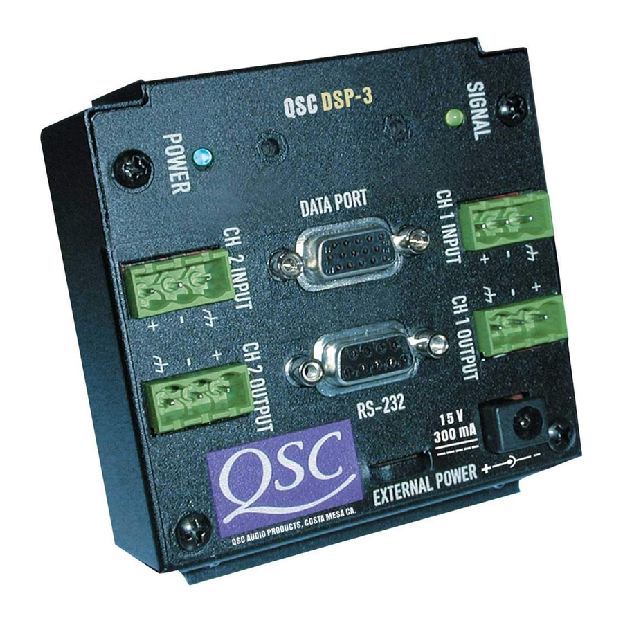
FRONT PANEL CH 1 OUTPUT, CH2 OUTPUT-- These terminal- block jacks provides post-DSP (processed) signal from the DSP-3 for downstream devices (ampli- fiers, monitoring busses, daisy-chaining the pro- cessed signal to a second amplifier). In the case of non-DataPort amplifiers, these are the DSP-3 output that gets connected to your amplifier’s... -
Page 13: Rear Panel
Basic Connector & Indicator Descriptions REAR PANEL DATAPORT (unlabeled)- This is the “output” DataPort. If the DSP-3 is directly mounted on a 2-RU QSC DataPort equipped amplifier, this connector plugs into the amplifier’s DataPort connector. If used with 3-RU QSC DataPort equipped amplifi-... -
Page 14: Hardware Features And Functions
Section 1: Introduction- DSP-3 Hardware Features (full set available to QSC DataPort equipped amplifiers): High- and Low-Pass Crossover High- and Low-Pass Shelf Filter Output Peak Limiter Multiple Delays List of Functions & Features Selectable responses: Butterworth (6,12,18 or 24 dB per octave slope) - Page 15 Section 1: Introduction- Parametric EQ Adjustable frequency Adjustable gain Adjustable Q factor Ability to bypass all EQ with a single mouse click Ability to add or delete EQ Graphical response curve provided in software Assignable anywhere in the signal chain Signal Compressor Adjustable attack and release times Adjustable Gain...
-
Page 16: Block Diagram
Section 1: Introduction- Block Diagram... -
Page 17: Power Supply
Section 1: Introduction- This portion of the introduction provides some of the technical details of the DSP-3. Audio Input Path There are two audio channels each with two input connectors, a balanced 3-pin ‘euro’ terminal block jack and an electronically balanced DataPort input. -
Page 18: Section 2: Installation
1- Configure the amplifiers DIP switches (QSC amplifiers where the DSP-3 covers the configuration switches) as follows: •All filters off 2- Align the DataPort plug on the back of the DSP-3 with the DataPort jack on the back of the amplifier and gently push the DSP-3 to seat the connector. -
Page 19: Mounting To The Accessory Remote Mounting Bracket
REMOTE MOUNTING THE DSP-3 : 4-Channel CX and DCA , Powerlight series, and all non-QSC amplifiers Use of the DSP-3 with the 4-channel CX and DCA and all Powerlight amplifiers requires the remote mounting of the DSP-3. Use with non- QSC amplifiers also requires remote mounting. -
Page 20: Connecting Audio Inputs And Outputs
CONNECTING AUDIO INPUTS AND OUTPUTS: The audio inputs and outputs of the DSP-3 use 3-pin “Phoenix”-type (Euro-style) terminal block connectors. These connectors allow pre- wiring of inputs without any soldering and allow for rerouting of audio inputs by simply interchanging connector locations without the need for any tools. -
Page 21: Connecting To The Dataport Of The Dsp-3
232 port and finger-tighten the retaining screws. DSP-3 setup and programming takes place through the RS-232 port. Any time setup changes are required to the DSP-3, it must be connected to its host computer through the RS-232 port. If “real-time” control of the DSP- 3 is required, the RS-232 port connection must be maintained as well. -
Page 22: Daisy-Chaining The Dsp-3 Outputs
The terminal block outputs are active even when the DataPort connections are used. To daisy-chain the DSP output, connect the output jacks of the DSP-3 to the input jacks of the next amplifier. Make sure that all interconnecting cables are balanced and connected properly. -
Page 23: Applications Examples
DSP-3 Directly Mounted to QSC Amplifier. Audio Inputs via Terminal Block Inputs DSP-3 Directly Mounted to QSC Amplifier. Networked OR Local Control. Audio Inputs via DataPort. NOTE: External accessory power supply may be required on older models, see page 2 for full application information. - Page 24 Installation- Application Examples DSP-3 Remotely Mounted used with QSC DataPort Amplifier. Audio Input via Terminal Block Inputs DSP-3 Directly Mounted to QSC Amplifiers, Networked Control via QSCcontrol Products NOTE: External accessory power supply may be required on older models, see Appendix for application information.
- Page 25 Section 2: Installation- Application Examples DSP-3 Remotely Mounted connected to any Non-DataPort Amplifier. Audio Input via Terminal Block Inputs...
-
Page 26: System Requirements
• The last applied configuration that is “running” in the DSP-3 when it is turned off becomes the active configuration again once the power is turned back on to the DSP-3. This ensures that the system “comes up” just as it was left last time it was powered down. -
Page 27: Specifications
(full scale) 18.0 or 14.5 dBu 15.5 or 12.0 dBv Output impedance 600 Ohms balanced Amplifiers one 2-Ch. amplifier per DSP-3 Amplifier status monitor Clip indicator Senses channel clipping Protect indicator Senses amplifier protect status (status monitoring not available for non-DataPort amplifiers) - Page 28 Section 3: Specifications General Physical Height 3.50 inches Width 3.75 inches Depth 1.38 inches Weight 0.59 lbs (0.27 kg) Mounting Direct mount to amplifier or remote mount Operating temperature 0 to 50° Celsius Dimensions Accessory External Power Supply AC Input Voltage 80–240 VAC AC Input Current 0.3 Amps rms...
-
Page 29: Architect's And Engineer's Specifications
+4 dBu and maximum level of +21 dBu. Input connectors shall be of the “Phoenix” detach- able terminal block type. Control— The DSP shall be configurable via RS-232 or via a networked DataPort connection. The Digital Signal Processor shall be the QSC DSP-3. -
Page 30: Dataport Pinout
Appendix- DataPort Pinout DATA PORT PINOUT The diagram below shows the pin assign- ments used for the HD-15 connectors on the DSP-3 and amplifier. NOTE! This information is shown for reference only and is subject to change without no- tice as the DataPort feature is specific to QSC products and not intended for inter- face to other manufacturer’s equipment. -
Page 31: Rs-232 Pinout
Section 5: Appendix- RS-232 Port Pinout & Connector P-N’s RS-232 PINOUT: The diagram below shows the pin assignments for the RS-232 connector on the DSP-3. Note that Pin #9 is used for Contact Closure function (normally not used in RS-232). -
Page 32: Application Information
As design improvements are continuous, the following information is subject to change. Contact QSC for current information. QSC’s DSP-3 Module has been designed to attach directly to the DataPort connector of QSC’s CX, DCA, Powerlight, and Powerlight 2 series amplifiers. When attached to CX, DCA, and Powerlight 2 amps manufactured 08/99 and later, the module receives its power through the DataPort from the amplifier. -
Page 33: Preset Operation Notes
“just the math”. If building a new configuration from scratch, when you apply it to the DSP-3 you will also be prompted to save it to disk as a Configuration file. -
Page 34: Maintenance, Warranty & Qsc Contact Information
If the DSP-3 is returned to the factory for service, it should be sent in the proper QSC carton. If you did not save the original carton, ask your QSC dealer for one or call QSC to have one sent to you. -
Page 36: Copyright 2001, Qsc Audio Products, Inc
PH: (714) 754-6175 FAX: (714) 754-6174 © Copyright 2001, QSC Audio Products, Inc. QSC® is a registered trademark of QSC Audio Products, Inc., Costa Mesa, CA “QSC” and the QSC logo are registered with the U.S. Patent and Trademark Office...
Need help?
Do you have a question about the DSP-3 and is the answer not in the manual?
Questions and answers