
Related Manuals for YOKOGAWA UM330


Summary of Contents for YOKOGAWA UM330
- Page 1 Instruction Manual Models UM350/UM330 Digital Indicator with Alarms User’s Manual IM 05F01D02-41E IM 05F01D02-41E 1st Edition...
- Page 2 Blank Page...
- Page 3 (2) Read this manual carefully to gain a thorough understanding of how to operate this product before starting operation. (3) This manual describes the functions of this product. Yokogawa M&C Corporation (hereinafter simply referred to as Yokogawa) does not guarantee the application of these functions for any particular purpose.
-
Page 4: Safety Precautions
Draws attention to information that is essential for understanding the operation and/or features of the indicator. I Regarding Force Majeure Yokogawa M&C Corporation assumes no liability for any loss or damage, direct or indirect, caused by the use of or unpredictable defects of the product. IM 05F01D02-41E... -
Page 5: Table Of Contents
Toc-1 <Int> <Rev> Models UM350/UM330 Digital Indicator with Alarms User’s Manual IM 05F01D02-41E 1st Edition CONTENTS Installation ....................1-1 Model and Suffix Codes .................. 1-1 How to Install ....................1-2 How to Connect Wires ..................1-5 Hardware Specifications ................1-7 Terminal Wiring Diagrams ................ - Page 6 Blank Page...
-
Page 7: Installation
Suffix Code Description UM350 Digital indicator with Alarms (provided with retransmission output and 15 V DC loop power supply as standard) UM330 Standard type with three alarms Type Standard type with three alarms (with 24 V DC loop power supply) None... -
Page 8: How To Install
<Toc> <1. Installation> How to Install NOTE To install the indicator, select a location where: no one may accidentally touch the terminals, mechanical vibrations are minimal, 150 mm corrosive gas is minimal, temperature can be maintained at about 23 C and 150 mm 150 mm the fluctuation is minimal,... - Page 9 "N" stands for the number of controllers to be installed. However, the measured value applies if N +0.8 +0.8 (25) Unit: mm UM330 91.8 Small bracket Small bracket 1 to 10 mm (Panel thickness) Front of indicator General installation 145 min.
- Page 10 (top mounting hardware) Terminal board Direction to insert the indicator Insert the indicator into the opening at the front of the panel. Small bracket (bottom mounting hardware) Note: Right and left mounting for UM330. IM 05F01D02-41E 1st Edition : May 31,2000-00...
-
Page 11: How To Connect Wires
I For DC Relay Wiring I For AC Relay Wiring UM350/UM330 External AC power supply UM350/UM330 External DC power supply... - Page 12 Power supply, grounding, relay contact outputs 600 V PVC insulated wires, JIS C 3307, 0.9 to 2.0 mm Thermocouple Shielded compensating lead wires, JIS C 1610, (See Yokogawa Electric's GS 6B1U1-E.) Shielded wires (three conductors), UL2482 (Hitachi Cable) Other signals Shielded wires...
-
Page 13: Hardware Specifications
<Toc> <1. Installation> Hardware Specifications PV Input Signals • Number of inputs: 1 (terminals • Input type: Universal input system. The input type can be selected with the software. • Sampling period: 250 ms • Burnout detection: Functions at TC, RTD, standard signal (0.4 to 2 V or 1 to 5 V) Upscale, downscale, and off can be specified. - Page 14 3 terminals (NC, NO, Common); 1c Display Specifications • PV display: 4-digit, 7-segment red LED display, character height of 20 mm (for both UM350 and UM330) • Setpoint display: 4-digit, 7-segment, red LEDs, character height of 9.3 mm (for both UM350 and UM330) •...
- Page 15 • Dimensions: UM350 96 (W) 96 (H) 100 (depth from panel face) mm UM330 96 (W) 48 (H) 100 (depth from panel face) mm • Installation: Panel-mounting type. With top and bottom (or right and left) mounting hardware (1 each) •...
- Page 16 • Normal operating conditions: Ambient temperature: 0 to 50 C (40 C or less for side-by-side close installation) 0 to 40 C if the 24 V DC loop power supply of Model UM330 is used Temperature change rate: 10 C/h or less...
-
Page 17: Terminal Wiring Diagrams
1-11 <Toc> <1. Installation> Terminal Wiring Diagrams NOTE Do not use unassigned terminals as relay terminals. Terminal wiring diagrams are shown on and after the next page. IM 05F01D02-41E 1st Edition : May 31,2000-00... - Page 20 Blank Page...
-
Page 21: Initial Settings
See “3.2 Setting Alarm Setpoints.” Indicator operation The following explanation of operation for the UM350’s panel, shown in the figure, is the same as that of the UM330’s panel. IM 05F01D02-41E 1st Edition : May 31,2000-00... -
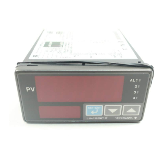
Page 22: Names And Functions Of Front Panel Parts
<Toc> <2. Initial Settings> Names and Functions of Front Panel Parts 1. Process 1. Process variable (PV) variable (PV) display display 2. Parameter 3. Alarm indicator Setpoint lamps display 3. Alarm indicator keys lamps keys 2. Parameter 4. SET/ENT Setpoint display 4. -
Page 23: Setting Pv Input Type (Setting First At Power-On)
<Toc> <2. Initial Settings> Setting PV Input Type (Setting First at Power-on) NOTE • The indicator displays the operating display when the power is turned on. However, if PV input type has not been set, “IN” appears. In this case, first use the key to display the input range code to use, then press the key to register it. - Page 24 <Toc> <2. Initial Settings> Press the key once to register the Press the key once to display the SET/ENT SET/ENT setpoint. parameter “RL” (minimum value of PV input range). Displays parameter “RL”. SET/ENT SET/ENT Press the key once to display the SET/ENT parameter “UNIT”...
- Page 25 <Toc> <2. Initial Settings> I Instrument Input Range Codes Instrument Input Instrument Input Type Measurement Accuracy Range Code Input Range Set the data item PV Input Type "IN" to the OFF option to leave the PV input Set the data item PV Input Type "IN" to the OFF option to leave the PV input Unspecified type undefined.
- Page 26 <Toc> <2. Initial Settings> NOTE The indicator may automatically initialize the registered operating parameter setpoints if any change is made to the data item PV Input Type (IN), Maximum Value of PV Input Range (RH), Minimum Value of PV Input Range (RL), PV Input Decimal Point Position (SDP), Maximum Value of PV Input Scale (SH) or Minimum Value of PV Input Scale (SL).
-
Page 27: Changing Pv Input Type
<Toc> <2. Initial Settings> Changing PV Input Type The following operating procedure describes an example of changing the setting of K-type thermocouple (-199.9 to 500.0 C) to RTD Pt100 (-199.9 to 500.0 C) and a measurement range of 0.0 to 200.0 C. PV input terminal Thermocouple/mV/V input...... - Page 28 <Toc> <2. Initial Settings> Press the key once to register the Press the key once to display the SET/ENT SET/ENT setpoint. parameter “RL” (minimum value of PV input range). Displays parameter “RL”. SET/ENT SET/ENT Press the key once to display the SET/ENT parameter “UNIT”...
-
Page 29: Changing Alarm Type
<Toc> <2. Initial Settings> Changing Alarm Type The following operating procedure describes an example of changing alarm-1 (factory-set default: PV high limit alarm) to PV low limit alarm. When you have changed alarm type, the alarm setpoint will be initialized; set the alarm setpoint again. - Page 30 2-10 <Toc> <2. Initial Settings> Press the key once to register the Press the key for more than 3 sec- SET/ENT SET/ENT setpoint. onds. This returns you to the display shown at power-on (figure below). Displays PV. SET/ENT SET/ENT You can take the same steps for alarm-2 type (AL2), alarm-3 type (AL3), and alarm-4 See “3.2 Setting Alarm Setpoints”...
-
Page 31: Setting Hysteresis In Alarm Setpoint
2-11 <Toc> <2. Initial Settings> Setting Hysteresis in Alarm Setpoint The following operating procedure describes an example of setting a 5.0°C hysteresis level in the alarm setpoint. Bring the operating display into view Press the key several times to SET/ENT (appears at power-on). - Page 32 Blank Page...
-
Page 33: Operations
<Toc> <3. Operations> Operations This chapter describes key entries for operating the indicator. If you cannot remem- ber how to carry out an operation during setting, press the key for more than 3 SET/ENT seconds. This brings you to the display (operating display) that appears at power- NOTE Do not use the instrument generating strong magnetic field such as radio equipment and the like near the indicator. -
Page 34: Setting Alarm Setpoints
<Toc> <3. Operations> Setting Alarm Setpoints The following operating procedure describes an example of setting a value of 160.0 in the alarm-1 setpoint parameter. Before setting the alarm setpoint, check the alarm type. To change the alarm type, see “2.4 Changing Alarm Type.” Alarm output terminals Factory-set defaults Alarm-1 (terminal numbers... -
Page 35: Troubleshooting And Maintenance
<Toc> <4. Troubleshooting and Maintenance> Troubleshooting and Maintenance Troubleshooting I Troubleshooting Flow If the operating display does not appear after turning on the indicator’s power, try to solve the problem by following the procedure below. If the problem seems to be complex, contact the vendor from which you purchased the instrument. - Page 36 <Toc> <4. Troubleshooting and Maintenance> I Errors at Power on The following table shows errors that may be detected by the fault diagnosis function when the power is turned on. Error indication Description Control Alarm Retransmission Communi- Remedy (on PV display unit) of error output output...
- Page 37 <Toc> <4. Troubleshooting and Maintenance> I If a Power Failure Occurs during Operation G Momentary Power Failures shorter than 20 ms The indicator is not affected at all and continues normal operation. G Momentary Power Failures of 20 ms or longer •...
-
Page 38: Maintenance
<Toc> <4. Troubleshooting and Maintenance> Maintenance This section describes the cleaning and maintenance of the UM350/UM330. 4.2.1 Cleaning The front panel and operation keys should be gently wiped with a dry cloth. NOTE Do not use alcohol, benzine, or any other solvents. - Page 39 <Toc> <4. Troubleshooting and Maintenance> I Attaching Terminal Cover The procedure for attaching the terminal cover is as follows. Do not touch the terminals on the rear panel when power is being supplied to the indicator. Doing so may result in electric shock. Before attaching the terminal cover, turn off the source circuit breaker and use a tester to CAUTION check that the power cable is not conducting any electricity.
-
Page 40: Replacing Parts With A Limited Service Life
<Toc> <4. Troubleshooting and Maintenance> 4.2.4 Replacing Parts with a Limited Service Life The following UM350/UM330 parts have a limited service life. The service life given in the table assume that the controller is used under normal operating conditions. Part... -
Page 41: Parameters
<5. Parameters> Parameters This chapter contains a parameter map as a guideline for setting parameters, and lists of parameters for recording User Settings. Parameter Map SET/ENT UM350/UM330 Parameter Map Press the key once. SET/ENT SET3S Press the key for 3 seconds. -
Page 42: Lists Of Parameters
<Toc> <5. Parameters> Lists of Parameters * Parameters relating to PV should all be set in real numbers. For example, use temperature values to define alarm setpoints for temperature input. * The “User Setting” column in the table is provided for the customer to record setpoints. * Numbers in ( ) are the parameter setpoints that apply when the communication func- tion is used. - Page 43 <Toc> <5. Parameters> I Setup Parameters G Alarm/Communication Related Parameters Parameter Name of Parameter Setting Range and Description Initial Value User Setting Symbol Alarm-1 type OFF (0) 1: PV high limit (energized, no stand-by action) (AL1) 2: PV low limit (energized, no stand-by action) 9: PV high limit (de-energized, no stand-by action) 10: PV low limit (de-energized, no stand-by action) 11: PV high limit (energized, stand-by action)
- Page 44 <Toc> <5. Parameters> Parameter Name of Parameter Setting Range and Description Initial Value User Setting Symbol Parity 0: None 1: Even (PRI) 2: Odd Stop bit 1, 2 (STP) Data length 7, 8 Fixed at 7, when the P.SL parameter is set to (DLN) MODBUS (ASCII).
- Page 45 <Toc> <5. Parameters> Parameter Name of Parameter Setting Range and Description Initial Value User Setting Symbol DI function selection OFF (0): The external contact input is disabled. 1: Resets the values of the PEAK and BOTM operating parameters to an off-to-on transition (DIS) of the DI1 input.
- Page 46 <Toc> <5. Parameters> I List of Alarm Types The table below shows the alarm types and alarm actions. In the table, codes 1, 2, 9, and 10 are not provided with stand-by actions, while codes 11, 12, 19, and 20 are provided with stand-by actions. Alarm type code Alarm type code Alarm action...
- Page 47 <Toc> <5. Parameters> I Useful Operating Display (SELECT Display) Registering frequently changed parameters in the SELECT display after ordinary operating displays will allow you to change settings easily. A maximum four displays can be regis- tered. Useful operating display (SELECT display) Ordinary operating displays (example) S E T / E N T...
- Page 48 Blank Page...
- Page 49 <Int> <Toc> Revision Information G Title : Models UM350/UM330 Digital Indicator with Alarms User’s Manual G Manual No. : IM 05F01D02-41E May 2000/1st Edition Newly published Written by Products Documents Controllers & Conditioners Division Yokogawa M&C Corporation Published by Yokogawa M&C Corporation...
- Page 50 Blank Page...
Need help?
Do you have a question about the UM330 and is the answer not in the manual?
Questions and answers