
Related Manuals for Sensus PolluStat E


Summary of Contents for Sensus PolluStat E
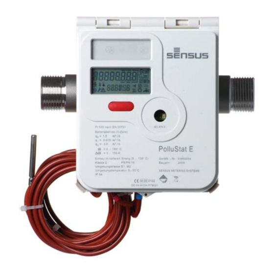
- Page 1 Heating / Cooling meter PolluStat E Installation and operating instructions PolluStat E Installation and operating instructions M H 4110 INT PolluStat E, page 1...
-
Page 2: Table Of Contents
These installation and operating instructions specify the installation and the operation of PolluStat E and its variants. It is an essential part of the delivered items and has to be handed over to the final user. Delivered items ... -
Page 3: Technical Data
220 ... 240 V AC 4. Installation of sub assemblies resp. 24 V AC Frequency: 50/60 Hz Depending on the version PolluStat E can be Max. power consumption: 0.5 VA used as a heating meter, as a cooling meter or as Cable length: ca. -
Page 4: Flow Sensor
DN 50 to DN 100: Both ultrasonic transducers in the flow sensor have to be in horizontal position. For this reason the PolluStat E has to be installed with the integrator turned upwards. In case of removed and separately mounted integrator this is valid accordingly. -
Page 5: Installation Of Temperature Sensors
(to extend the length of the temperature sensor cables by max. 23 m, recommended cable type I-Y(St)Y 2x2x0.8, minimum core size 0.5 mm²). Allocation as Fig. 4: Exemplary diagram follows: for nominal size DN 50 M H 4110 INT PolluStat E, page 5... - Page 6 (see fig. 7). cable binder for strain relief cable binder for strain relief Fig. 9: Example of four-wire connection Fig. 6: Example of two-wire connection with a screened cable M H 4110 INT PolluStat E, page 6...
-
Page 7: Display Options
Heating / Cooling meter PolluStat E Installation and operating instructions 5. Display options 5.1 User menu The different display options of PolluStat E are Error message divided into six menus. Depending on the type of (only in case of error) -
Page 8: Target Day Menu
Return to selection menu Maximum heating resp. (depress for 2 seconds) cooling power in selected month with date (averaged) * Maximum heating resp. cooling power in selected month with time (averaged) * M H 4110 INT PolluStat E, page 8... -
Page 9: Service Menu
* Absolute maximum Return to selection menu temperature in colder line (depress for 2 seconds) with date * Current date * Current time * Next target date * Operating days * M H 4110 INT PolluStat E, page 9... -
Page 10: Control Menu For Tariff Purposes
Now the desired items can be selected by short meters) keystrokes, the values can be set in the same way as entering the password. Return to selection menu (depress for 2 seconds) M H 4110 INT PolluStat E, page 10... -
Page 11: Functional Test, Sealing
7. Possible error situations Err C010 or D010 sensors in warmer and colder line resp. sensors are not connected PolluStat E is equipped with an automatic self- Err 0002 Air in flow sensor checking function. As soon as an error is detected, the display shows a four-digit error code Error situation „Err 1010“... -
Page 12: M-Bus Plug-In Module Acc. To En 13757-3
(left front). The computational work for the modules may only be permitted in the designated The required parameters for slots mounted. meter type physical unit and pulse value serial number initial meter reading M H 4110 INT PolluStat E, page 12... -
Page 13: Optional Integrated Data Logger
8.11 Combined heating / cooling meter 4 cross slot screws Sealing of the half shells with user seal (see Descriptive name: PolluStat E H or PolluStat EX H fig. 12) This PolluStat E version switches over at an Mounting bracket with hole automatic switch-over point between metering heating and cooling energy. -
Page 14: Declaration Of Mid Conformity
Heating / Cooling meter PolluStat E Installation and operating instructions Declaration of MID conformity M H 4110 INT PolluStat E, page 14... - Page 15 Heating / Cooling meter PolluStat E Installation and operating instructions Space for extra notes: M H 4110 INT PolluStat E, page 15...
- Page 16 Subject to change without notice Sensus GmbH Ludwigshafen Industriestraße 16 D-67063 Ludwigshafen Telefon: + 49 (0) 621 6904-1113 Fax: + 49 (0) 621 6904-1409 Qualitätsmanagementsystem Quality Austria-zertifiziert E-Mail: info.de@xyleminc.com Nach ISO 9001, Reg.-Nr. 3496/0 M H 4110 INT PolluStat E, page 16...
Need help?
Do you have a question about the PolluStat E and is the answer not in the manual?
Questions and answers