Table of Contents
Advertisement
Quick Links
Download this manual
See also:
User Manual
Advertisement
Table of Contents

Related Manuals for SGM P-5


Summary of Contents for SGM P-5
- Page 1 P‐5 WASH LIGHT P‐5 WHITE P‐5 TUNABLE WHITE...
-
Page 2: Series Dimensions
P-5 series dimensions Measurements in millimetres and inches (in brackets). Drawing not to scale. - Page 3 The SGM logo, the SGM name and all other trademarks in this document pertaining to services or products by SGM or its affiliates and subsidiaries are trademarks owned or licensed by SGM or its affiliates or subsidiaries.
-
Page 4: Table Of Contents
Contents P-5 series dimensions ......................2 Safety information ......................7 Overview ..........................10 Parts identification and terminology .................11 Preparing for installation ....................12 Installing the P-5 ......................13 Connecting AC Power ......................15 Configuring the device .....................16 Configuring the device using an Android telephone via RFID ..................16 Master/Slave configuration ............................ - Page 5 About DMX ..................................22 Setting the DMX address............................... 22 Setting the DMX mode..............................23 Full Color Calibration and Color Temperature Correction (P-5 only) ................25 Device personality settings ....................26 Setting the dimming curve ............................. 26 Flipping the OLED display ............................. 26 Setting the OLED display saver.............................
- Page 6 Devices and accessories ....................55 Included items................................55 Ordering information ..............................55 User’s notes ........................57...
-
Page 7: Safety Information
Read the safety precautions in this section before unpacking, installing, powering or operating this product. The P-5 series luminaries are multi-environmental devices with an IP-rating of 65, intended for professional use only. It is not suitable for household use. Impropre a l’usage domestique. - Page 8 Preventing burns and fire WARNING! Take measures to prevent burns and fire. • Install in a location that prevents accidental contact with the device. • Install only in a well-ventilated space. • Install at least 0.3 m (12 in.) away from objects to be illuminated. •...
- Page 9 Avoid personal injury WARNING! Take measure to prevent personal injury. • Do not look directly at the light source from close range. • Take precautions to prevent injury due to falls when working at height. • For permanent installation, ensure that the device is securely fastened to a load-bearing surface with suitable corrosion- resistant hardware.
-
Page 10: Overview
White Emitter LED’s. The P-5 W is similar, but incorporating white-emitting LEDs. The P-5 TW offers the ability to adjust white color temperature to 2200, 3000, 4000 or 5300K. The P-5’s all provide built-in wireless DMX support, stand-alone programs, dimming, and a lamp life expectancy of 50,000 hours*. The P-5’s also offer a variation of beam angles with 15°, 21°... -
Page 11: Parts Identification And Terminology
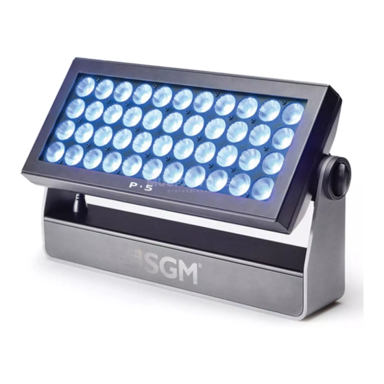
Parts identification and terminology 44 x 10 W LEDs Base Safety wire eyelet Cooling fans Tilt lock DMX in and out Wireless antenna socket OLED display Control panel Power connections Tilt lock... -
Page 12: Preparing For Installation
Unpack the device and inspect it to ensure that it has not been damaged during transport. ™ The P-5 is shipped with two quarter-turn brackets, that can be used to mount the device at elevation, and a W-DMX wireless antenna. -
Page 13: Installing The P-5
Installing the P-5 The P-5 may be installed in any orientation, but if installed horizontally with a downward beam-angle, water can potentially pool in the fan wells. Under normal operation the moisture will evaporate. However, in loca- tions with high rainfall, you may wish to fab-... - Page 14 Two quarter-turn brackets are supplied with the device if it is to be flown above the ground. Remove the floor stand/base and rig the P-5 to a support truss or structure using the supplied brackets and suitable clamps. Fasten a safety cable (not shown) between the support structure and the attachment point on the device.
-
Page 15: Connecting Ac Power
Connecting AC Power The P-5 can operate on any 208–240 V, 50/60 Hz AC mains power supply. It draws approximately 2 amps at full power. For permanent installation, have a qualified electrician wire the mains cable directly to a suitable branch circuit. ... -
Page 16: Configuring The Device
Configuring the device using an Android telephone via RFID P-5 devices can also be configured wirelessly, via RFID, using the SGM Tool app installed on an Android smart phone that has NFC support (ISO 15693 and ISO 18000-3 mode 1 compatible, operating on 13.56 MHz ±7k Hz carrier frequency). -
Page 17: Master/Slave Configuration
Master/Slave configuration You can set a P-5 device to operate as master device to another P-5 device (which then becomes a slave device), or an entire group of P-5 devices (which then becomes slave devices). The assigned slave device(s) will mimic the settings of the master... -
Page 18: Setting A Static Color Manually
Setting a static color manually The device can be configured to display a predefined and static color using the “Manual→Quick color” menus (see “Control menu” on page 31). Note that whenever the “Manual→Quick color” settings are changed, the device will be set by default to automatically start in quick color mode whenever it is powered on. -
Page 19: Using Stand-Alone Operation
Using stand-alone operation Stand-alone operation is where the device is not connected to a control device, but is preprogrammed with a series of up to 24 scenes, that play continuously in a loop. Up to three stand-alone programs can be defined and run from the menus, and one of the programs can be set to run by default whenever the device is started. -
Page 20: Connecting To A Dmx Control Device
Connecting to a DMX control device The device is controllable using a DMX control device and it can be connected using either a DMX cable or via the P-5’s built- in wireless receiver system. If using a cabled DMX system, connect the DMX in cable (with male 5-pin XLR plug) and out cable (with female 5-pin XLR plug) to the DMX data link. -
Page 21: Attaching The W-Dmx™ G4 Wireless Receiver
™ The W-DMX G4 wireless receiver is supplied with the P-5 as an alternative to the wireless cone antenna receiver. Before you attach the wireless receiver, ensure that there is no DMX cable connected to the device. Attach the wireless DMX an- tenna to the connector on the back of the device. -
Page 22: Configuring The Device For Dmx Control
The first channel used to receive data from a DMX control device is known as the DMX start address. Each P-5 must have a DMX start address set. For example, if a P-5 has a DMX address of 10 and it is in 3-channel DMX mode, then it uses channels 10, 11, and 12. -
Page 23: Setting The Dmx Mode
Using the “DMX mode” menu available from the control panel, specify the DMX mode that provides the device controls that you require: P-5 DMX modes Function Individual control of color channels for red, green & blue. White is automatically mixed in. - Page 24 P-5 TW DMX modes Function Dimmer & white temperature control (2200k-5300K) White temperature control (2200K, 3000K, 4000K, and 5300K) Dimmer, white temperature control (2200K, 3000K, 4000K, and 5300K), shutter, strobe, pulse and open shutter effects. Fine and coarse control of white temperatures (2200K, 3000K, 4000K, and 5300K)
-
Page 25: Full Color Calibration And Color Temperature Correction (P-5 Only)
Full Color Calibration and Color Temperature Correction (P-5 only) All channel modes except 3 Channel Mode RGB: Lets you choose between raw or white-calibrated color (6500K default) via the Control Menu (“Settings→White Calibrated”) 3 Channel Mode RGB: Features full color calibration (irrespective of current color setting) when you mix 2 or 3 colors to ensure uniform color between products. -
Page 26: Device Personality Settings
Linear control provides uniform adjustment throughout the control action, whereas gamma corrected dimming provides finer control at low light levels, where the eye is more sensitive to change. By default, the P-5 uses gamma corrected dimming. For uniform response, set all devices to the same dimming curve. To set the desired dimming curve, use the “Settings→Dimming curve”... -
Page 27: Setting The Fan Mode
Setting the fan mode For operating environments where low-noise is a requirement or where the device will be operating in high temperatures, it is possible to adjust the default fan speed to low or high using the “Settings→Fan mode” menu. -
Page 28: Service
Service Apart from the lens module, there are no user-serviceable components in the device. Do not open the P-5, as doing so is likely to damage the ingress protection. Consult your SGM dealer if the device operates abnormally, is defective or otherwise in need of service or repair. - Page 29 Dismantle the front and unscrew the highlighted front plugs with an Unbrako 6/HOP6 Allen key. Take out the lens module. Place the new lens on the PCB print spacers and carefully press the lens module in place.
- Page 30 Screw in the highlighted front plugs with an Unbrako 6/HOP6 Allen key (Nm 1,0) and place three Silica Gel bags (not included in lens kit) as shown. Place the sealing frame (facing upwards - see below) on top of the lens module.
-
Page 31: Upgrading The Firmware
If in doubt, consult your SGM dealer for a suitable maintenance schedule. Clean the P-5 using a soft cloth dampened with a solution of water and a mild detergent. Do not use products that contain solvents, abrasives or caustic agents for cleaning, as they can cause damage to both hardware, cables and connectors. -
Page 32: P-5 Dmx Protocols
DMX protocols Configuring DMX is described “Setting the DMX mode” on page 23. P-5 DMX Protocols 3 Channel Mode - RGB plus automatic White Default Channel Name DMX value Description Info Fader type percentage value No RED > 0,0%... - Page 33 4 Channel Mode - RGBW Default Channel Name DMX value Description Info Fader type percentage value No RED > 0,0% 100,0% 0 (0%) Fade Maximum RED No GREEN > GREEN 0,0% 100,0% 0 (0%) Fade Maximum GREEN No BLUE > BLUE 0,0% 100,0%...
- Page 34 6 Channel Mode - RGBW plus Shutter Default Channel Name DMX value Description Info Fader type percentage value 0,0% 2,7% Closed 10 (3,9%) 3,1% 5,9% Open 0 (0%) 6,3% 59,2% Strobe Fast > Slow 0 (0%) Shutter 59,6% 68,6% Pulse - Open Slow >...
- Page 35 Default Channel Name DMX value Description Info Fader type percentage value No BLUE > BLUE 0,0% 100,0% 0 (0%) Fade Maximum BLUE No WHITE > WHITE 0,0% 100,0% 0 (0%) Fade Maximum WHITE...
- Page 36 8 Channel Mode (16 bit) - RGBW Default Channel Name DMX value Description Info Fader type percentage value No RED > 65535 0,0% 100,0% 0 (0%) Fade Maximum RED No GREEN > GREEN 65535 0,0% 100,0% 0 (0%) Fade Maximum GREEN No BLUE >...
- Page 37 9 Channel Mode (16 bit) - Intensity & RGBW Default Channel Name DMX value Description Info Fader type percentage value No light > Intensity 0,0% 100,0% 0 (0%) Fade Maximum light No RED > 65535 0,0% 100,0% 0 (0%) Fade Maximum RED No GREEN >...
- Page 38 10 Channel Mode (16 bit) - Intensity & RGBW Default Channel Name DMX value Description Info Fader type percentage value No light > Intensity 65535 0,0% 100,0% 0 (0%) Fade Maximum light No RED > 65535 0,0% 100,0% 0 (0%) Fade Maximum RED...
-
Page 39: P-5 W Dmx Protocols
P-5 W DMX Protocols 1 Channel Mode - Intensity Default Channel Name DMX value Description Info Fader type percentage value No light > Intensity 0,0% 100,0% 0 (0%) Fade Maximum light... - Page 40 2 Channel Mode - Shutter & Intensity Default Channel Name DMX value Description Info Fader type percentage value 0,0% 2,7% Closed (3,9%) 3,1% 5,9% Open 0 (0%) 6,3% 59,2% Strobe Fast > Slow 0 (0%) Shutter Snap 59,6% 68,6% Pulse - Open Slow >...
- Page 41 2 Channel Mode (16 bit) - Intensity Default Channel Name DMX value Description Info Fader type percentage value No light > Intensity 65535 0,0% 100,0% 0 (0%) Fade Maximum light...
-
Page 42: P-5 Tw Dmx Protocols
P-5 TW DMX Protocols 2 Channel Mode - Intensity with CTC Default Channel Name DMX value Description Info Fader type percentage value No light > Intensity 0,0% 100,0% 0 (0%) Fade Maximum light 0,0% 100,0% 2200K-5300K 0 (0%) Fade... - Page 43 6 Channel Mode - Shutter, Intensity & individual White control Default Channel Name DMX value Description Info Fader type percentage value 0,0% 2,7% Closed (3,9%) 3,1% 5,9% Open 0 (0%) 6,3% 59,2% Strobe Fast > Slow 0 (0%) Shutter Snap 59,6% 68,6% Pulse - Open...
- Page 44 Default Channel Name DMX value Description Info Fader type percentage value WHITE 0,0% 100,0% 4000K 0 (0%) Fade WHITE 0,0% 100,0% 5300K 0 (0%) Fade 8 Channel Mode (16 bit) - Individual White control Default Channel Name DMX value Description Info Fader type percentage...
-
Page 45: Control Menu
Displays product type. Firmware Version Displays installed software version. Serial Number Displays serial number. RDM ID Displays RDM ID (for use with the SGM Tool App). DMX View Displays received DMX levels. Displays device temperatures Temperatures MB: LED: (Mainboard and LED panel) - Page 46 Level 1 Level 2 Level 3 Function Info LED On Time Displays LED on time (Red, Green, Blue, and White) (continued) R: G: B: W: LED On Time Resettable R: G: B: W: Displays recorded operating data and error codes. Debug Service use only.
- Page 47 Level 1 Level 2 Level 3 Function Settings Wireless DMX Wireless DMX Disables wireless DMX out operation. (continued) (continued) out disable Startup Mode Select Startup Default operating mode when device is powered on: Mode 1. Quick Color 2. Stand-alone 3. DMX (factory default) Startup Program Stand-alone program 1, 2, or 3.
- Page 48 Low fan speed for quiet operation. Max Power High fan speed for maximum cooling effect. Always Full High fan speed with no adjustment. Power Minimum values Min. Red (P-5) Adjust default minimum setting (0-1000). Min. Green (P-5) Min. Blue (P-5)
- Page 49 Level 1 Level 2 Level 3 Function Settings Minimum values Min. White (P-5) (continued (continued) Min. Line 1 (P-5 W) Min. Line 2 (P-5 W) Min. Line 3 (P-5 W) Min. Line 4 (P-5 W) Min. 3000 (P-5 TW) Min. 2200...
- Page 50 Level 1 Level 2 Level 3 Function Settings Minimum values Min. 4000 (continued (continued) (P-5 TW) Min. 5300 (P-5 TW) RFID Write Refresh Rate Factory Default Reset the device to factory default settings. Service Pin Service Menu Manual Quick Color Red (P-5) Static quick color - red mix (0-255).
- Page 51 (continued) color startup mode. White Static quick color - white mix (0-255). Sets device to quick (P-5/ P-5 W) color startup mode. 2200K (P-5 TW) Static quick color - white temperature 2200K mix (0-255). Sets device to quick color startup mode.
- Page 52 Green value in currently selected scene (0-255). Blue (P-5) Blue value in currently selected scene (0-255). White White value in currently selected scene (0-255). (P-5 / P-5 W) 2200K (P-5 TW) 2200K white temperature value in currently selected scene (0-255). 3000K (P-5 TW) 3000K white temperature value in currently selected scene (0-255).
- Page 53 Level 1 Level 2 Level 3 Function Manual Editor 5300 (P-5 TW) 5300K white temperature value in currently selected scene (continued) (continued) (0-255). Shutter Shutter setting in currently selected scene (0-255): Shutter Blackout (0-7) Shutter Open (8-15) Variable Strobe (16-151)
- Page 54 Level 1 Level 2 Level 3 Function Manual Editor Wait Time (Sec.) Wait (static) time in current scene in sec. (0-59). (continued) (continued) Test Stops test sequence execution. Automated Test Initiates a self-test sequence. Burn-in Test Service use only. (30 min.) Display Test Service use only.
-
Page 55: Devices And Accessories
Accessory Holder (P-series)........................Order no: 83061119 Barn door 4-way ............................Order no: 83061120 Barn door 8-way ............................Order no: 83061121 Barn door color frame..........................Order no: 83061122 SGM USB uploader cable .......................... Order no: 83062011 Flight case (4 devices - P-5/Q-7/X-5) ......................Order no: 82051501... - Page 56 APPROVALS AND CERTIFICATIONS Certified to ............................CSA Std. C22.2 No. 166 Conforms to................................UL Std. 1573 Conforms to........................2006/95/EC: Low Voltage Directive Conforms to..........................2011/65/EU: RoHS2 Directive 4008543 The information in this document is subject to change without notice...
-
Page 57: User's Notes
User’s notes... - Page 58 SGM A /S · Sommer vej 23 · 8210 Aarhus V · Denmark Tel +45 70 20 74 00 · info@sgmlight.com · www.sgmlight.com...
Need help?
Do you have a question about the P-5 and is the answer not in the manual?
Questions and answers