Advertisement
Owner's Manual & Safety Instructions
Save This Manual
operating, inspection, maintenance and cleaning procedures� Write the product's serial number in the
back of the manual near the assembly diagram (or month and year of purchase if product has no number)�
Keep this manual and the receipt in a safe and dry place for future reference�
email our technical support at: productsupport@harborfreight.com
When unpacking, make sure that the product is intact
and undamaged� If any parts are missing or broken,
please call 1-888-866-5797 as soon as possible�
©
Copyright
2017 by Harbor Freight Tools
No portion of this manual or any artwork contained herein may be reproduced in
any shape or form without the express written consent of Harbor Freight Tools�
Diagrams within this manual may not be drawn proportionally� Due to continuing
improvements, actual product may differ slightly from the product described herein�
Tools required for assembly and service may not be included�
Keep this manual for the safety warnings and precautions, assembly,
Visit our website at: http://www.harborfreight.com
®
� All rights reserved�
read this material before using this product.
Failure to do so can result in serious injury.
SaVe tHiS ManuaL.
17i
Advertisement
Table of Contents

Related Manuals for AMES 1000a


Summary of Contents for AMES 1000a
- Page 1 Owner’s Manual & Safety Instructions Save This Manual Keep this manual for the safety warnings and precautions, assembly, operating, inspection, maintenance and cleaning procedures� Write the product’s serial number in the back of the manual near the assembly diagram (or month and year of purchase if product has no number)� Keep this manual and the receipt in a safe and dry place for future reference�...
- Page 2 table of contents Safety ������������������������������������������2 Operation ������������������������������������� 8 Specifications ������������������������������5 Maintenance �������������������������������15 Setup �������������������������������������������6 Warranty �������������������������������������16 WarninG SyMBOLS anD DeFinitiOnS This is the safety alert symbol� It is used to alert you to potential personal injury hazards� Obey all safety messages that follow this symbol to avoid possible injury or death�...
- Page 3 iMpOrtant SaFety inFOrMatiOn Safety Warnings and precautions read all safety warnings and all instructions. Failure to follow the warnings and instructions may result in electric shock, fire and/or serious injury. Save all warnings and instructions for future reference. 1� Electrical shock can cause death f�...
- Page 4 1000 VDC or 750 VAC� marked as blank on the scale� 17� Do not test current on circuits 28� Have Meter calibrated by a higher than 1000A� qualified technician every year 18� Dress properly� Protective, to maintain accurate results�...
- Page 5 Ranges: 60A / 600A / 1000A Frequency Range: 40-400Hz Inrush Current Accuracy (@0A-60A) Reference only; (@600A-1000A) ± 5�0% of rdg + 60D Resistance Ranges: 600Ω / 6kΩ / 60kΩ / 600kΩ / 6MΩ / 60MΩ Resistance Accuracy (@600Ω-600kΩ) ± 0.8% of rdg + 3D (@6MΩ-60MΩ) ±...
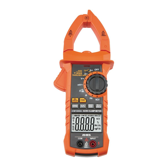
- Page 6 Setup - Before use: read the entire iMpOrtant SaFety inFOrMatiOn section at the beginning of this manual including all text under subheadings therein before set up or use of this product. Functions current clamp Worklight ncV indicator clamp trigger rotary Switch relative/ inrush Button...
- Page 7 Display Symbol Description Alternating current Direct current Indicates that display data is being held Auto Power-Off autO Auto range mode Inrush mode Continuity Diode test Relative measurement mode Non-contact voltage detection The maximum value is being measured The minimum value is being measured Battery low Percent (Duty cycle) Ω, kΩ, MΩ...
- Page 8 Operating instructions read the entire iMpOrtant SaFety inFOrMatiOn section at the beginning of this manual including all text under subheadings therein before set up or use of this product. electrical shock can cause death or injury! neVer tOucH exposed conductors of electricity.
-
Page 9: Data Hold
Backlight and Worklight 1� Press the B.L HOLD button for 3� While in current range modes, two or more seconds to turn on the turning the backlight on also LCD backlight for 30 seconds� turns the clamp Worklight on� 2� Press the B.L HOLD button for note: Frequent use of the backlight will two or more seconds again to... -
Page 10: Current Measurement
Measurement Operation note: Remove plugs from note: Test Lead probes have removable ends of Test Leads (included) covers for overvoltage protection� With before connecting to Meter� covers in place, Test Leads are rated for use with CAT IV circuits� Exposed probes are rated for use with CAT II circuits�... - Page 11 inrush current Measure inrush current of AC conductors 4� Read measured inrush current carrying up to 1000 amperes� on the Display� The current is only measured once and the 1� Turn the Rotary Switch to the reading is held on the Display� 60/600 or 1000 position, depending on the amperage of...
- Page 12 Frequency/Duty cycle Measurement Measure frequency up to 10MHz� note: Frequency and duty cycle modes cannot be used while in minimum and maximum value mode� in current Mode WarninG! Remove test leads 3� Press Hz% to choose between before taking measurements frequency and duty cycle modes�...
-
Page 13: Resistance Measurement
resistance Measurement Measure circuit resistance up to 60M Ohms� 4� Read measured resistance on the Display� WarninG! To prevent electric shock, turn off all power and fully discharge capacitors 5� When testing is complete, turn on the circuit under test before measuring� Rotary Switch to OFF, remove Test Leads and store with Meter�... -
Page 14: Capacitance Measurements
Diode Measurement Test voltage drop in diodes� 4� Connect red probe to diode’s anode and black probe to its cathode� WarninG! To prevent electric shock, turn off all power and fully discharge capacitors 5� Read measured forward-biased on the circuit under test before measuring� voltage drop on the Display�... -
Page 15: Battery Replacement
Maintenance and Servicing procedures not specifically explained in this manual must be performed only by a qualified technician. cleaning, Maintenance, and Lubrication 1� Wipe unit with a dry, lint-free cloth� 3� Store unit in a dry location� Do not use solvents or abrasives� 4�... - Page 16 Limited 90 Day Warranty Harbor Freight Tools Co� makes every effort to assure that its products meet high quality and durability standards, and warrants to the original purchaser that this product is free from defects in materials and workmanship for the period of 90 days from the date of purchase� This warranty does not apply to damage due directly or indirectly, to misuse, abuse, negligence or accidents, repairs or alterations outside our facilities, criminal activity, improper installation, normal wear and tear, or to lack of maintenance�...
Need help?
Do you have a question about the 1000a and is the answer not in the manual?
Questions and answers