Table of Contents
Advertisement
QSC26404 User's Manual
QSC26404 Net DVR
User Manual
V2.1
Contact Us:
Q-See Products
8015 E. Crystal Dr
Anaheim, CA 92807
Website:
http://www.q-see.com
Customer Service:
Phone: 877-998-3440 x 538
Email: cs@dpsi-usa.com
Tech Support:
Phone: 877-998-3440 x 539
Email: ts@dpsi-usa.com
Fax:
714-998-3509
Rev 092007D
1
Advertisement
Table of Contents

Related Manuals for Q-See QSC26404


Summary of Contents for Q-See QSC26404
-
Page 1: User Manual
QSC26404 User’s Manual QSC26404 Net DVR User Manual V2.1 Contact Us: Q-See Products 8015 E. Crystal Dr Anaheim, CA 92807 Website: http://www.q-see.com Customer Service: Phone: 877-998-3440 x 538 Email: cs@dpsi-usa.com Tech Support: Phone: 877-998-3440 x 539 Email: ts@dpsi-usa.com Fax: 714-998-3509... -
Page 2: Table Of Contents
External Alarm Input and Relay Output ... 57 5.14 Network Parameters ... 62 5.15 Accessing the DVR Over a Network ……………………………………………... 5.16 Accessing the DVR From a Remote Computer …………………………………... 5.17 PTZ (Pan, Tilt, Zoom) ... 67 QSC26404 User’s Manual... - Page 3 How to make a RS-232 connect cable ... 83 How to make a UTP network connect cable ... 83 Appendix D Specifications ... 85 Appendix E Troubleshooting ... 86 Appendix F Product Service & Warranty... 87 Appendix G Customer Information Card ... 88 QSC26404 User’s Manual...
- Page 4 Thank you for purchasing our Net DVR. This manual applies to the QSC26404 model. Please read this Manual carefully to ensure that you can use the device correctly and safely. DISCLAIMER: The contents of this Manual are subject to change without notice;...
-
Page 5: Chapter 1 Product Introduction
The QSC26404 has both the features of a digital video recorder (DVR) and a digital video server (DVS). It can work as stand alone, or be used to build a powerful surveillance network, widely used in banking, telecommunications, transportation, factories, warehouses, irrigation, etc. -
Page 6: Network Functions
Supports PTZ local and remote control. Supports multi-lever user management. Supports local and remote search log function. Automatic recovery from exceptions leads to high reliability. SDK and demo source code available to shorten the application development time. QSC26404 User’s Manual... -
Page 7: Chapter 2 Installation
Chapter 2: Installation Warning: Before you install the DVR, please make sure the power to the DVR is switched off. 2.1 Checking the DVR and Its Accessories When you get the product, check that all the items are included in your product package. -
Page 8: Rear Panel Description
2.3 Rear Panel Description Fig 2-1 QSC26404 Rear Panel 1- Video in 4- Alarm out 7-USB 2.0 Port 10- Ethernet port QSC26404 User’s Manual 2- Video out 3-VGA video out 5- RS485 T+ T- R+ R- 6- Power switch 8- Audio in... -
Page 9: Chapter 3 Operational Instructions
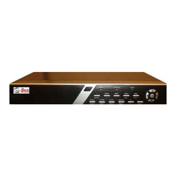
QSC26404 User’s Manual Fig 3-1 Front Panel Description IR receiver for remote control. Green means DVR is working; Red means DVR is powered off; Green means you can use IR remote control. Blinking means data is transmitting. Input number, lower case, upper case character and symbols. - Page 10 SHIFT Control Direction Keys Keys ENTER QSC26404 User’s Manual 【AUTO】in PTZ control. 1. Manual record; 2. 【SHOT】in PTZ control (adjust preset). 1. Enter into PTZ control mode; 2. 【IRIS-】in PTZ control.. Multi screen preview switch; Switch menu mode into preview;...
-
Page 11: Ir Remote Control
PLAY INFO VOIP MENU PREV Direction Keys ENTER QSC26404 User’s Manual Description Turnoff device. Enable/Disable IR remote control Same as numeric keys on front panel. Same as EDIT key on front panel. Same as A key on front panel. Same as REC key on front panel. -
Page 12: Powering Down The Dvr
Press【DEV】key, input the DVR device ID (default is “88”, can be changed in “Display” menu) and then press the 【ENTER】 key. If the “STATUS” light of the DVR front panel is green, it means you can use the remote control to operate the DVR. Disabling the Remote Control When the remote control status is on, press【DEV】key again, the “STATUS”... -
Page 13: Menu Description
Alarm out schedule Copy to alarm out Exceptions Add or delete user User Password setup or modification Password User rights setup QSC26404 User’s Manual Form 3-3 List of Menu Options Menu Name Image Network Utilities Function Select camera Camera name... -
Page 14: Menu Operation
(【↑】 【↓】). When the “Active Frame” is located on an icon, you can press the【ENTER】key to enter into the sub menu. For example, move the “Active Frame” to the “Image” icon, press 【ENTER】to enter into the sub menu as in following fig 3.4: QSC26404 User’s Manual Fig 3.3 Main menu... - Page 15 Press【A】key to select number, upper case, lower case or symbols; 【→】 【←】 b) Use QSC26404 User’s Manual 【 ↑】 【↓】 【←】 【→】 ) . The different kinds of menu items keys to move cursor;...
-
Page 16: Input Text
Press【A】key to change input methods. You can select “Number”, “Uppercase”, “Lowercase” or “Symbol”. Uppercase Lowercase Symbol There are 24 symbols in all. They are divided into 4 pages, and you can use 【0】 key to go to the next page. QSC26404 User’s Manual... -
Page 17: Chapter 4 Basic Operation Guide
HDD is not installed or not detected. If HDD is not detected, please contact administrator. Note: If HDD is not installed or not detected, DVR will beep an alarm. You can disable the beeping in the “alarm” menu ->”Exceptions” option. - Page 18 QSC26404 User’s Manual Fig 4.1 Recording status Form 4-1 Camera record status Icon Icon Color Status Description White No video signal Yellow Video input Pink Manual recording Green Real time recording Blue Motion detection recording External alarm recording...
- Page 19 Press 【 EDIT】 key to manual cycle preview. You can set the auto preview mode in “Preview” menu, refer to Chapter 5.11. Press【PREV】key to switch to multi-screen view. QSC26404 User’s Manual Fig 4.2 Alarm status Form 4.2 Camera alarm status...
-
Page 20: User Name And Password
User Name and Password Note: When the DVR is delivered from the factory, there is only one default administrator named “admin”, administrator’s name can not be modified, while the password can be modified. The administrator can create 15 users and define their user rights. - Page 21 QSC26404 User’s Manual Fig 4.5 Main menu Step 2: Select the objective user name by using 【↑】,【↓】 then move the “Active Frame” to “Password” icon by using【】/【】keys. As fig 4.6 shows: Fig 4.6 Change users’ password...
-
Page 22: Ptz (Pan, Tilt, Zoom) Control
PTZ control interface. In menu mode, press 【 PTZ】 key, you can enter into PTZ control interface directly, shown in the following picture: QSC26404 User’s Manual Fig 4.7 PTZ Control interface... -
Page 23: Select Channel
In PTZ control mode, press 【 REC/SHOT】 key, and press the preset number (three numeric keys), DVR will adjust the corresponding preset number. Repeat pressing 【REC/SHOT】key, and press the preset number, DVR will adjust that preset number. When you exit PTZ control mode, the camera will stay at the current position. -
Page 24: Manual Record
Press【ESC】or【ENTER】to exit and return to preview mode. 4.5 Manual Record Note: In order to record the user must have recording rights, DVR has HDD, and HDD is formatted. In preview mode, press【REC】key, in the pop-up login dialog box, select a user name and input the correct password, you will enter into the “Manual Record”... -
Page 25: Playback
Manual record interface has the following parts: channel number, channel status, start/stop record, start all and stop all buttons. Channel: Lists the channel numbers that the DVR has. Status: Channel work status has 4 status options: the channel is recording (including real time recording, alarm recording, motion detection recording). - Page 26 Backup Devices: You can select USB flash, USB HDD, USB CD-R/W to backup the files or clips. Copy: Start to backup. Backup Today: Backup all recorded files from today. Operation when played back QSC26404 User’s Manual Fig 4.10 Playback interface...
- Page 27 Copy segment: 【 EDIT】 ; Stop copy: 【 EDIT】 (you need a back up device to store the segment) Exit: 【ESC】 Note: When DVR is busy, if you select high play speed, there may be a difference in actual play speed. Exit playback In playback interface, press【ESC】key to enter into preview mode.
- Page 28 4.11: There is an additional bar that appears. We call it the control bar. Control Bar Functions: QSC26404 User’s Manual Fig 4.11 Play back control bar You can click these buttons to skip backward or forward 3% at a time.
-
Page 29: Backup Recorded Files
【ENTER】key, all recorded files for the day of all channels will be backed up to the save device. A pop-up dialog box will display the backup status. If the backup device is not connected correctly or DVR does not detect the backup device, an exception dialog box will pop-up. Please ask administrator for more information. - Page 30 4) After you select all segments, press【ESC】key, a message window will pop-up. If you press the “Confirm” button, the DVR will start to backup the selected segments. If you press the “Cancel” button, DVR will abort backup. QSC26404 User’s Manual...
-
Page 31: Shutting Down The Dvr
You can use our file player software to playback the video segment on a PC. You can find the player software on the included CD. Exit playback interface Please refer to Chapter 4.6. 4.8 Shutting Down the DVR Note: You can only turn off the power directly using the rear panel switch. QSC26404 User’s Manual... -
Page 32: Chapter 5 Parameters Setup Guide
Chapter 5: Parameters Setup Guide Only the users that have “Parameters Setup” right need to read this chapter. When the following parameters are modified and saved, you must reboot the DVR to make the new parameters effective. Other parameters do not require a reboot. - Page 33 QSC26404 User’s Manual Fig 5.1 Enter into user menu Move “Active Frame” to “User” icon, press【ENTER】key to enter into “User Management” menu shown in fig 5.2 Fig 5.2 User management...
-
Page 34: Add And Delete User
5.2 Add and Delete Users Enter into “User Management” interface. Add User The steps are as follows: Step 1: Enter into “User Management” menu shown in fig 5.4 Please refer to Chapter 5.1 QSC26404 User’s Manual Fig 5.3 Error... - Page 35 In the user’s list box of “User Management” menu, use 【 】 【 】 keys to select the new user name, then use【】key to go to the password edit box. Press【EDIT】key to enter into edit box, use numeric keys to input the new password. QSC26404 User’s Manual Fig 5.4 user management Fig 5.5 Input user name...
- Page 36 In the “User Management” menu, press “Confirm” button, the user’s password and rights will be saved and you will return to the main menu. If you press the “Cancel” button, the configuration will be abandoned. QSC26404 User’s Manual Fig 5.6 Setup user rights...
- Page 37 Com Control: DVR RS-232 transparent channel function. MAC Address This MAC address is not the address of DVR but the PC that will access DVR. If you setup this MAC address, only the PC with this MAC address can access this DVR.
-
Page 38: Unit Name And Device Id
There is an item called “Unit Name”. The default unit name is “Embedded Net DVR”. Move “Active Frame” to unit name edit box, press【EDIT】key to enter into edit status, you can modify the unit name. For instructions on how to input characters, please refer to Chapter 3.4. -
Page 39: Video Output Standard And Vga Setup
When you use the remote control to operate the DVR, you must use the device ID to select the DVR. The default device ID is “88”. If there is more than one DVR in one place, please setup different device IDs for each DVR, otherwise the remote control will control all the DVRs with the same device ID at the same time. -
Page 40: Camera Name And Osd (On Screen Display) Setup
The disable flag is “×”. If you enable the check box, you can setup the camera name position. You can copy the position to any other camera. The setup steps are: QSC26404 User’s Manual Fig 5.9 Input camera number... - Page 41 System Time In “Display” menu, you can setup DVR system date and time. Move your active frame to “Date/Time setup” and press enter. Date Display Mode: Move the active frame to Date Display Mode then press 【EDIT】...
-
Page 42: Video Parameters Setup
You can setup each camera individually, and you can also copy the video parameters of one camera to any other cameras. Here are the setup steps: Step 1: Enter into “Camera”, select a camera then enter “Color setup” menu shown as fig5.12 QSC26404 User’s Manual... - Page 43 Or you can repeat set 2 and step 3 to adjust for any other camera. After adjusting, in “Image Setup” menu, press “Confirm” button to save the parameters and make them effective. Otherwise, press “Cancel” button or【ESC】key to abort modification. QSC26404 User’s Manual Fig 5.12 Color setup...
-
Page 44: Mask Area Setup
After you setup the red mask area, press【EDIT】key to save the mask area. The maximum mask area size is 8*8 panels and the minimum size is only one panel. You can setup 4 mask areas at most. QSC26404 User’s Manual Fig 5.13 Mask area setup... - Page 45 In “Advanced setting” menu, press the “Confirm” button to save the mask area, press “Cancel” button to abort. Here is an example of the mask area function shown as fig 5.14: Disabling the mask check box cancels the mask area. QSC26404 User’s Manual Fig 5.14 Area masked...
-
Page 46: View Tampering Alarm
5.8 View Tampering Alarm If you enable this function, when someone blocks the camera spitefully, the DVR will send a warning alarm. Step 1: Enter into “Camera” menu: Step 2: Select camera: Please use【】 【】keys to select a camera. Step 3: Select sensitivity: move active frame to sensitivity item right beside the “View tampering”... -
Page 47: Video Loss Alarm
By selecting the “Off” option for “View Tampering”, you can delete the view tampering area. Note: Only one view tampering area can be setup for each camera. The view tampering area can not be copied. If the schedule is modified, you must reboot the DVR to make the parameters effective. - Page 48 Step 4: Setup alarm schedule: You can setup a working schedule. The DVR will only respond when the video loss occurs during the schedule. Note: The 4 time periods can not be repeated. Please reboot the DVR to make parameters effective.
-
Page 49: Motion Detection
There are 7 options, from 0 (the lowest) to 5 (the highest) and “Off”. You can use 【 ↑】 【 ↓】 keys to select one. If you select the “Off” option, the DVR will not response even if there is motion detected. - Page 50 Step 5: Motion alarm policy: Move “Active Frame” to the corresponding “Policy” button of motion detection alarm, press 【ENTER】 key to enter into “Motion Alarm Handle” menu shown as fig 5.18: QSC26404 User’s Manual Press【A】key to clear all motion areas.
- Page 51 DVR will switch to the related camera. If you trigger more than one camera, the DVR will pop them up one by one every 10 seconds. When the motion alarm ends, the DVR will return to preview mode.
-
Page 52: Preview Properties
Step 1: Enter into “Preview” menu: In the main menu, move the “Active Frame” to “Preview” icon and press【ENTER】, you willl enter into “preview” menu as shown in fig 5.19 QSC26404 User’s Manual Fig 5.19 Setup preview mode... - Page 53 Step 2: Preview properties: Preview mode: For preview mode item, you can use 【 ↑】 【 ↓】 key to select one mode. If DVR has only 1 channel, you can select only “1 Screen” option. If DVR has 4 channels, there are “1 Screen”...
-
Page 54: Recording Setup
“Overwrite” option, when the HDD in the DVR is full, the DVR will overwrite the earliest recorded files and continue recording. If you select “Stop recording” option, when the HDD is full the DVR will handle it as a “Hard Disk Full” exception, please refer to Chapter 5.17 for exception menu. - Page 55 Bit Rate Type: The DVR will use the fixed bit rate to compress image. The bit rate size is defined in “Bit Rate” option. With this option we can calculate the recorded file size and network bandwidth that we need.
- Page 56 Detection” in order to trigger motion recording (refer to Chapter 5.10). If record type is “Alarm” or other related type, you must setup “Alarms” in order to trigger alarm recording (refer to Chapter 5.13). The time period is between 00:00—24:00. QSC26404 User’s Manual...
-
Page 57: External Alarm Input And Relay Output
5.13 External Alarm Input and Relay Output For QSC26404 there are 4 alarm in and 1 relay out ports. In “Alarms” menu, you can setup each external alarm input. In main menu, move the “Active Frame” to “Alarms” icon and press【ENTER】key to enter into alarms menu as shown in fig 5.22... - Page 58 Description: If “On Screen Warning” is enabled, when an external alarm occurs and the DVR is in preview mode, the DVR will display the related camera. If you trigger more than one camera, the DVR will display them one by one every 10 seconds. When the external alarm ends, the DVR will return to preview mode.
- Page 59 Step 9: Copy the parameters to other external alarm input: You can copy the parameters of current alarm input to other external inputs. Step 10: Save setup: In “Alarms” menu, press “Confirm” button to save the parameters. Press “Cancel” button or【ESC】key to abort. QSC26404 User’s Manual Fig 5.24 PTZ linkage setup...
- Page 60 Step 6: Save setup When you finish setup, in the “Alarms” menu, press the “Confirm” button to save all parameters. Note: If any schedule is modified, you must reboot the DVR to make it effective. QSC26404 User’s Manual Fig 5.25 Alarm out schedule...
- Page 61 QSC26404 User’s Manual Exceptions The exceptions that can currently be handled include: hard disk full, hard disk error, illegal access, IP address conflict, network failure, and NTSC/PAL difference. Enter into the “Exceptions” menu as shown in fig 5.26 Fig 5.26 Exceptions setup Includes the following handle methods: Audible Warning: the DVR will beep.
-
Page 62: Network Parameters
IP address: This IP address must not be conflict with another IP address on the router. If there is a DHCP server in the network, you can set the IP as “0.0.0.0”, save and reboot the DVR. In reboot process, the DVR will search the DHCP server and get one dynamic IP address. This item will display the dynamic IP address. - Page 63 Remote Host IP and Port: If you set this IP and port, when there is an alarm and exception happens, the DVR will send information to that host IP. The center with this IP can receive alarm and exception information from the DVR. You can use SDK to develop this center software.
- Page 64 Step 6: Save parameters. In the “Network” menu, press “Confirm” to save parameters. Reboot the DVR to make parameters effective. In the reboot process, the DVR will start dialup using PPPoE function. If the DVR dials into the internet successfully, the DVR will display the dynamic internet IP address in the “Network”...
-
Page 65: Accessing The Dvr Over A Network
To access the DVR through a computer you need to make sure the default gateway on the DVR is the same IP address as your router, and the first three sets of numbers of the DVR IP address are the same as the first three sets of numbers of router’s address. Example: if your router’s default gateway is 192.168.1.1 then the default gateway setting in the DVR should be... -
Page 66: Accessing The Dvr From A Remote Computer
To access the DVR from a remote computer, in addition to the above steps, you will also need to forward ports 80 and 8000 on the router the DVR is attached to, to the IP address of the DVR. How you would do this depends on the brand and model number of your router. You can go to www.portforward.com... -
Page 67: Ptz (Pan, Tilt, Zoom)
5.17 PTZ (Pan, Tilt, Zoom) There is one RS-485 port on the DVR rear panel used for PTZ camera control. You can setup RS-485 parameters to match your PTZ protocol. In main menu, move the “Active Frame” to PTZ icon and press【ENTER】key, you will enter into PTZ menu as shown in fig 5.29 PTZ menu description Select channel: Select a PTZ camera. - Page 68 Note: In the DVR “PTZ” menu, if you select Pelco-P protocol when you setup PTZ address please plus or minus one compared with Camera ID. For example, if camera ID is 2, the DVR PTZ address is set as ID 3.
- Page 69 Note: Please make sure the PTZ camera you are using can support the preset function. Sequence setup In “PTZ” menu, press “Setup” button on the right side of “Sequence No”, you will enter into the “Sequence” setup menu as shown in fig 5.31 QSC26404 User’s Manual Fig 5.31 PTZ sequence setup...
- Page 70 Press “Return” button to return to the “PTZ” menu. In “PTZ” menu, press “Confirm” button to save this cruise. Note: Please make sure the PTZ camera you are using can support the cruise function. QSC26404 User’s Manual Fig 5.32 Cruise setup...
-
Page 71: Chapter 6 Utilities
“Upgrade”, “Hard Disk”, “Stop Alarm Out”, “Reboot”, “Power Off”, “View Log” and “System Info”. Enter into “Utilities” menu as shown in fig 6.1 Restore Parameters Restore factory parameters for the DVR. The IP address, gateway and port number will not be restored. Shown as fig 6.2 QSC26404 User’s Manual Fig 6.1 Utilities... -
Page 72: Upgrade
Input the ftp server IP and press【ENTER】key. DVR will connect with FTP server through the network and download the firmware file. If you select “USB” mode, please make sure you connect a USB flash drive to the DVR and the firmware file is in the root directory of the flash drive. -
Page 73: Hard Disk Management
Check HDD work status Capacity, Free space, Stand by or not, Normal status or not. Format HDD Before formatting stop all recording. After formatting, you must reboot the DVR, otherwise DVR will not work correctly. 6.4 Stop Alarm Out Clear the alarm output manually. -
Page 74: View Log
In the “Utilities” menu, press “View Log” to enter into “Log” menu as shown in fig 6.6 If you want to view the log based on the default option, just press 【 ENTER】 key. The DVR will list all matched information. You can also select options to search “By Type”, “By Date”, or “By Type&Date”. - Page 75 Step 3: Move “Active Frame” to “Search Log” button, press 【 ENTER】 key to start searching. Step 4: When searching is finished, DVR will list all matched alarm information. In the list box, the information includes: Index, Occur Time, Major Type, Minor Type, Panel User, Net User, Host Address, Para.
-
Page 76: System Information
Step 5: After finishing search, the DVR will list the matched log information. Step 6: Press “Return” button to return to “Utilities” menu. System Information Press the “System Info” icon in the “Utilities” menu, you will get DVR system information as shown in fig 6.7 QSC26404 User’s Manual... -
Page 77: Chapter 7 Firmware Upgrade
Chapter 7: Firmware Upgrade The DVR firmware is stored in FLASH ROM. You can use the DVR upgrade function to write the firmware file (digicap) into FLASH. There are two cases where you need to upgrade DVR firmware. One is to update old firmware, the other is when the code in DVR FLASH has crashed. - Page 78 In the “User/Rights Security” Dialog box select “User Name” as “target”. In “Home Directory” edit box, input the path where the firmware file (digicap) is placed. Then press “Done” to exit. QSC26404 User’s Manual Fig 7.2 setup parameters Fig 7.3 Setup username Fig 7.4 username...
-
Page 79: Upgrade Mode
Please refer to the client software user manual for detail information. Use “FTP” function of “Upgrade” sub menu in “Utilities” menu. You need a host PC to run FTP server software and hold firmware file (digicap), and make sure DVR and PC are in the same subnet. -
Page 80: Appendix A Mouse Control Function
4. Area configuration interface Right click Pop-up menu including confirm, cancel, clear, full (this option only appears in motion detect area configuration) Drag the left key Extend or shrink area Moving The primary grid followed with cursor QSC26404 User’s Manual... -
Page 81: Test Input Interface
Single-click the right key Cancel the operation you did and back to the previous interface Scroll wheel forward Select previous file Scroll wheel backward Select next file Drag the left key Select an area to zoom in (For SAE\YAAN protocol) QSC26404 User’s Manual... -
Page 82: Appendix Bhdd Capacity Calculation
Appendix B: HDD Capacity Calculation To calculate total capacity needed by each DVR according to video recording (video recording type and video file storage time). Step 1: Use Formula (1) to calculate storage capacity needed for every hour: unit Mbyte. -
Page 83: Appendix Cdvr Connect Cable Definition
Suggestion: have a network cable test tool to test each cable made. Pin definition To make the network cable according to your actual needs there are two options: (1) Use the following method to make the network cable when DVR is connected to a network hub or switch. QSC26404 User’s Manual... - Page 84 QSC26404 User’s Manual The corresponding relationship of the direct cable (2) Use the following method to make the cross network cable when DVR is directly connected with client-end PC. The corresponding relationship of cross cable...
-
Page 85: Appendix D Specifications
Working humidity Size PAL: 176*144(QCIF), 352*288(CIF), 704*288(2CIF), 528*384(DCIF), 704*576(4CIF); NTSC: 176*120(QCIF), 352*240(CIF), 704*240(2CIF), 528*320(DCIF), 704*480(4CIF). QSC26404 User’s Manual QSC26404 H.264 PAL: 352*288 (CIF), NTSC: 352*240 (CIF) PAL: 352*288 (CIF), NTSC: 352*240 (CIF) 4-ch BNC (Electrical Level: 1.0Vp-p, resistance: 75Ω) 1-ch, BNC (Electrical Level: 1.0Vp-p, resistance: 75Ω) -
Page 86: Appendix E Troubleshooting
Client software can not view DVR live image. Notes: Place the DVR in well ventilated area so that it operates within the recommended range of temperature and humidity as in specifications. If the circuit board gets wet, dust on circuit board can cause a short circuit. The circuit board, plug and socket, housing fan and housing should be cleaned by brushing. -
Page 87: Appendix F Product Service & Warranty
In order to provide various services to you, please complete registration procedure after you purchase the product. Cut off or copy User’s Information Card and fax or mail it to us after the card is filled in. QSC26404 User’s Manual Contact Us: Q-See Products 8015 E. -
Page 88: Appendix G Customer Information Card
QSC26404 User’s Manual Appendix G Customer Information Card User’s Name Mr./Mrs. Company Name Post Address Postcode Phone Number E-mail Model Number of Product Serial Number of Product Purchase Date Distributor... - Page 89 QSC26404 User’s Manual Notes: Contact Us: Q-See Products 8015 E. Crystal Dr Anaheim, CA 92807 Website: http://www.q-see.com Customer Service: Phone: 877-998-3440 x 538 Email: cs@dpsi-usa.com Tech Support: Phone: 877-998-3440 x 539 Email: ts@dpsi-usa.com Fax: 714-998-3509...