Table of Contents
Advertisement
Installation Instructions
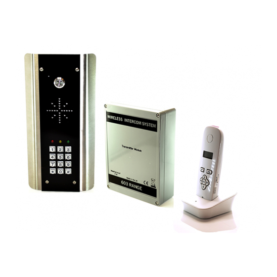
603 DECT Intercom
PROFESSIONAL INSTALL ONLY
Do NOT give this manual to end user!
,
Models 603-IBK
AB, ABK, HB, HBK, FB, FBK, IMP, IMPK
The manufacturer cannot legally offer technical support to non-qualified gate
or door installers. End users should employ the services of a professional
install company to commission or support this product!
Tip: Site Survey BEFORE you begin. See Page 3!
P a g e
| 1
Advertisement
Table of Contents

Related Manuals for AES 603 DECT


Summary of Contents for AES 603 DECT
-
Page 1: Installation Instructions
Installation Instructions 603 DECT Intercom PROFESSIONAL INSTALL ONLY Do NOT give this manual to end user! Models 603-IBK AB, ABK, HB, HBK, FB, FBK, IMP, IMPK The manufacturer cannot legally offer technical support to non-qualified gate or door installers. End users should employ the services of a professional install company to commission or support this product! Tip: Site Survey BEFORE you begin. -
Page 2: Table Of Contents
Contents …………….Pg 3 Overview of System …………….Pg 3 Site Survey …………….Pg 3 Wall / Pillar Mounting …………….Pg 4 Gooseneck / Pedestal Mounting …………….Pg 5 Mounting Speech Panels …………….Pg 6 Wiring …………….Pg 7 Keypad Overview …………….Pg 7 Keypad Programming …………….Pg 9 Using the Keypad …………….Pg 9 The Handset... -
Page 3: Overview Of System
Overview of System Please read this entire manual before attempting to install this system. This system should only be installed by a professional automatic gate installer or access control specialist installer. It is recommended that the system be range tested on site BEFORE being fully installed. Site Survey Before installing this system, you need to be sure that the range of the system will be sufficient. -
Page 4: Gooseneck / Pedestal Mounting
Gooseneck / Pedestal Mounting Lightning prone areas must use Surge protector transmitter Intercom Speech Transmitter point Keep High! 24v dc PSU 603 Range Power cable (2x1mm / 16 gauge) Power (2x1mm / 16 gauge) Screened CAT5 included. (8m / yards MAX) Tip: For shorter distances, some installs may mount transmitter on pedestal for convenience. -
Page 5: Mounting Speech Panels
Mounting Architectural Panels Loosen top 2 screws only Hinge front door Side View Mounting Hooded Panels Loosen top 2 screws only Hinge front door Call Button Optional keypad module Side View Mounting Flush Panels Call Button Optional keypad module Remove Side View Flush with surface Tip: Use appropriate fixings to ensure the intercom cannot be removed from the wall. -
Page 6: Wiring
Wiring Speech Unit Transmitter IMPORTANT Speaker Screen connection Volume 2x1mm (16AWG) WARNING: ESD Sensitive components Relays Code Optional Keypad SCREENED CAT5 Relay2 setting 8 metres/yards max) 24v DC Optional extra Relay3 antenna To Gate controller or lock WARNING: Do not use any other power source other than that Power provided. -
Page 7: Keypad Overview
Keypad overview This keypad has 3 outputs. The diagram below shows the LED indicators which indicate programming and relay status information. RED when incorrect codes entered and outputs are locked out. GREEN when output 1 activated. RED when output 2 activated. CLEAR when output 3 activated FAST FLASHING –... - Page 8 Enter or delete new user codes There are 3 groups of user codes. Group 10 for relay 1, group 20 for relay 2, and group 30 for relay 3. The programming sequence is shown below… 10= relay 1 codes Memory locations 2= add code (1000 available) 000-999 for relay 1...
-
Page 9: Using The Keypad
When the master code is forgotten…. 1) Wire a push button (or replicate with wire link) across the Egress terminal and (-)GND. 2) Switch off power for 1 minute. 3) Switch ON power. 4) during the first 60 seconds, press the EG button once to enable the function. 5) Enter the following code.. -
Page 10: Re-Coding Or Adding A Handset
Re-coding Handset/Adding Extra Handset Occasionally a system may need re-coded once installed. If the handset does not ring when the call button is pressed, it may need re-coded. The procedure for doing this is the same as for adding an additional handset as follows… Transmitter PCB Handset 1.Press and HOLD... -
Page 11: Adjusting Relay Time
Adjusting Relay time Press Relay 2 button for 3 seconds, scroll through menu until you see ‘ti’. Press OK to select ‘ti’ and adjust your relay times. Press OK to select your relay time. Press the right arrow end the process. - Page 12 Regulatory Compliance FCC Id: 2ALPX-603TX and 2ALPX-603EH Grantee: Advanced Electronic Solutions Global Ltd This device complies with Part 15D of FCC rules. Operation is subject to the following two conditions: (1) this device may not cause harmful interference, and (2) this device must accept any interference received, including interference that may cause undesired operation.
Need help?
Do you have a question about the 603 DECT and is the answer not in the manual?
Questions and answers