Table of Contents
Advertisement
CD RDS RECEIVER
DEH-5200SD
CD RECEIVER
DEH-5250SD
DEH-5250SD
DEH-5290SD
This service manual should be used together with the following manual(s):
Model No.
Order No.
CX-3269
CRT4488
For details, refer to "Important Check Points for Good Servicing".
PIONEER CORPORATION
PIONEER ELECTRONICS (USA) INC. P.O. Box 1760, Long Beach, CA 90801-1760, U.S.A.
PIONEER EUROPE NV Haven 1087, Keetberglaan 1, 9120 Melsele, Belgium
PIONEER ELECTRONICS ASIACENTRE PTE. LTD. 253 Alexandra Road, #04-01, Singapore 159936
PIONEER CORPORATION 2009
Mech. Module
S11STD-DOUT
CD Mech. Module : Circuit Descriptions, Mech. Descriptions, Disassembly
4-1, Meguro 1-chome, Meguro-ku, Tokyo 153-8654, Japan
DEH-5200SD/XNEW5
/XNES
/XNES1
/XNID
Remarks
ORDER NO.
CRT4508
/XNEW5
K-ZZZ. NOV. 2009 Printed in Japan
Advertisement
Table of Contents

Related Manuals for Pioneer DEH-5200SD/XNEW5


Summary of Contents for Pioneer DEH-5200SD/XNEW5
- Page 1 PIONEER CORPORATION 4-1, Meguro 1-chome, Meguro-ku, Tokyo 153-8654, Japan PIONEER ELECTRONICS (USA) INC. P.O. Box 1760, Long Beach, CA 90801-1760, U.S.A. PIONEER EUROPE NV Haven 1087, Keetberglaan 1, 9120 Melsele, Belgium PIONEER ELECTRONICS ASIACENTRE PTE. LTD. 253 Alexandra Road, #04-01, Singapore 159936 PIONEER CORPORATION 2009 K-ZZZ.
-
Page 2: Safety Information
Transistors Q101 in PCB drive the laser diodes. When Q101 is shorted between their terminals, the laser diodes will radiate beam. If the top cover is removed with no disc loaded while such short-circuit is continued, the naked eyes may be exposed to the laser beam. DEH-5200SD/XNEW5... - Page 3 To protect products from damages or failures during transit, the shipping mode should be set or the shipping screws should be installed before shipment. Please be sure to follow this method especially if it is specified in this manual. DEH-5200SD/XNEW5...
-
Page 4: Table Of Contents
10.3 KEYBOARD UNIT..........................60 10.4 CD MECHANISM MODULE........................62 10.5 WAVEFORMS ............................64 11. PCB CONNECTION DIAGRAM ........................66 11.1 TUNER AMP ASSY ..........................66 11.2 KEYBOARD UNIT..........................70 11.3 CD CORE UNIT(S11STD-DOUT)......................72 12. ELECTRICAL PARTS LIST .......................... 74 DEH-5200SD/XNEW5... -
Page 5: Service Precautions
The time taken to turn to the deteriorated mode is at a minimum around 20 seconds while the time to return to the normal mode is maximum 40 seconds approximately. Make sure to check the sound quality in the normal operation mode. area and a heat sink becomes hot areas. Be careful not to burn yourself. DEH-5200SD/XNEW5... -
Page 6: Notes On Soldering
Compared with eutectic solders, lead-free solders have higher bond strengths but slower wetting times and higher melting temperatures (hard to melt/easy to harden). The following lead-free solders are available as service parts: Parts numbers of lead-free solder: GYP1006 1.0 in dia. GYP1007 0.6 in dia. GYP1008 0.3 in dia. DEH-5200SD/XNEW5... -
Page 7: Specifications
2. SPECIFICATIONS 2.1 SPECIFICATIONS DEH-5200SD/XNEW5 General WAV signal format ....Linear PCM & MS ADPCM (Non-compressed) Power source ......14.4 V DC (10.8 V to 15.1 V allowable) Grounding system....Negative type USB standard specification Maximum current consumption ..........USB 2.0 full speed ..........10.0 A... - Page 8 WMA decoding format ..Ver. 7, 7.1, 8, 9, 10, 11 (2ch audio) Note (Windows Media Player) AAC decoding format...MPEG-4 AAC (iTunes en- Specifications and the design are subject to mod- coded only) (.m4a) ifications without notice. (Ver. 8.2 and earlier) DEH-5200SD/XNEW5...
-
Page 9: Disc/Content Format
2.2 DISC/CONTENT FORMAT DEH-5200SD/XNEW5... -
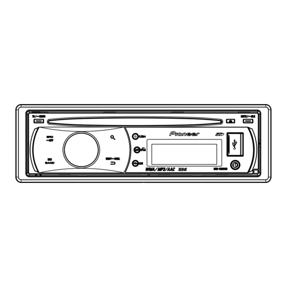
Page 10: Panel Facilities
CAUTION LIST / pending on the source. ENTER Use an optional Pioneer USB cable (CD-U50E) to While in the operating menu, connect the USB audio player/USB memory to press to control functions. the USB port. Since the USB audio player/USB memory is projected forward from the unit, it is dangerous to connect directly. -
Page 11: Head Unit
ENTER CAUTION While in the operating menu, Use an optional Pioneer USB cable (CD-U50E) to press to control functions. connect the USB audio player/USB memory to the USB port. Since the USB audio player/USB memory is projected forward from the unit, it is dangerous to connect directly. -
Page 12: Connection Diagram
2.4 CONNECTION DIAGRAM DEH-5200SD/XNEW5 DEH-5200SD/XNEW5... - Page 13 DEH-5250SD/XNES, DEH-5250SD/XNES1, DEH-5290SD/XNID DEH-5200SD/XNEW5...
- Page 14 DEH-5200SD/XNEW5...
-
Page 15: Basic Items For Service
See the table below for the items to be checked regarding audio: Item to be checked regarding audio Distortion Noise Volume too low Volume too high Volume fluctuating Sound interrupted DEH-5200SD/XNEW5... -
Page 16: Pcb Locations
3.2 PCB LOCATIONS CD Core Unit (S11STD-DOUT) Tuner Amp Assy Keyboard Unit A:DEH-5200SD/XNEW5 B:DEH-5250SD/XNES C:DEH-5250SD/XNES1 D:DEH-5290SD/XNID Unit Number QWM3122(A) Unit Number QWM3123(B,C,D) Unit Name Tuner Amp Assy Unit Number Unit Name Keyboard Unit Unit Number CWX3774 Unit Name CD Core Unit(S11STD-DOUT) -
Page 17: Jigs List
CD Mechanism Module 3.4 CLEANING Before shipping out the product, be sure to clean the following portions by using the prescribed cleaning tools: Portions to be cleaned Cleaning tools CD pickup lenses Cleaning liquid : GEM1004 Cleaning paper : GED-008 DEH-5200SD/XNEW5... -
Page 18: Block Diagram
4. BLOCK DIAGRAM TUNER AMP ASSY JA401 :DEH-5200SD/XNEW5 ANTENNA :DEH-5250SD/XNES :DEH-5250SD/XNES1 SYSTEM :DEH-5290SD/XNID COMP AMANT PEG645B FMANT PEG647A TUNL TUNPCE2 TUNPCE1 TUNPCK TUNPDO TUNPDI LDET LDET Q402 RDS_CK RDS_DATA RDSDT Q401 RDS_LOCK RDSLK RDS_HSLK RDS57K RESET SYS8V TUNER3V REG. ROM_VDD IC651 VDD3.3V... - Page 19 O_CIN JOYST ROT0 D7(SDIN) ROT1 Phase_A O_SID I2C_SDA/SPI_SOMI D6(SCLK) O_SCLK I2C_SCL/SPI_SIMO O_DC nRESET KYDT KYDT RSTB Q491 KYDT O_RST DPDT DPDT MED3.3V DPDT O_CSB MODE1/SPI_nSS SWVDD OEL+B OEL+B CN1811 USBDP USBDP USBDP USBDM USBDM USBDM VBUS VBUS USB5V USB5V DEH-5200SD/XNEW5...
- Page 20 10 9 8 18 19 5V → 3.3V EEPROM 5.0V AM ANT FMRF 3.3V 2.5V MIXER, IF AMP FM ANT DET, FM MPX, RDS DECODER FMRF RF adj ANT adj CF52 3.3V → 2.5V 2.5V 3.3V :DEH-5200SD/XNEW5 :DEH-5250SD/XNES :DEH-5250SD/XNES1 :DEH-5290SD/XNID DEH-5200SD/XNEW5...
-
Page 21: Diagnosis
In case of the above signal, the communication operative with Grille microcomputer may fail. If the time interval is not 500 msec, the oscillator may be defective. Source ON SYSPW <- H Pin 36 Completes power-on operation. (After that, proceed to each source operation) DEH-5200SD/XNEW5... -
Page 22: Error Code List
• How to restore from each error is shown below. classification, shown below. 0x, 1x and 3x: ACC-OFF then ON, CD-OFF then ON, 0x: Servo-related errors Disc ejection 1x: Servo-related errors 5X: ACC-OFF then ON, Disc ejection, Disc reloading 3x: Servo-related errors 5x: Mechanism-related errors DEH-5200SD/XNEW5... -
Page 23: Connector Function Description
5.3 CONNECTOR FUNCTION DESCRIPTION FRONT REAR OUTPUT OUTPUT WIRED REMOTE ANTENNA CONTROL SUBWOOFER 15 13 11 9 7 OUTPUT 16 14 12 10 8 A.ANT BREM B.UP DEH-5200SD/XNEW5... -
Page 24: Service Mode
When the power is turned on/off the gain of the RFAMP is reset to 0 dB. At the same time all the self-adjusting values shall return to the default setting. Do not do Tracking Servo Close before doing Focus Servo Close. (Because the overcurrent flows) DEH-5200SD/XNEW5... -
Page 25: Display Test Mode
SRC+RDM key REPEAT key To all turning To all turning SRC+RDM key REPEAT key To all turning off REPEAT key Screen ROM connection confirmation REPEAT key Media microcomputer information display REPEAT key Display Test Mode selection screen DEH-5200SD/XNEW5... - Page 26 If a number apparently strange is displayed as the EEPROM version: There may be a problem with the communication. If a version display is being made but the number of CH used is not displayed properly: The connection with the EEPROM may be defective. DEH-5200SD/XNEW5...
- Page 27 If nothing is displayed on the screen: There may be a problem with the communication, or the display microcomputer may have an error. If a number apparently strange is displayed as the media version: There may be a problem with the communication. DEH-5200SD/XNEW5...
-
Page 28: Disassembly
CD Mechanism Module. Panel Assy Fig.1 - Removing the Tuner Amp Assy (Fig.2) Remove the two screws. Remove the two screws. Straighten the tabs at six locations indicated and then remove the Tuner Amp Assy. Tuner Amp Assy Fig.2 DEH-5200SD/XNEW5... - Page 29 - Removing the Cover Remove the three hooks. Cover Remove the hook. Remove the hook. Remove the hooks in order of figure and then remove the cover. DEH-5200SD/XNEW5...
- Page 30 Mechanism Unit from the table. Keeping the Mechanism Unit lifted by holding these tabs with your fingers may result in deformation. 3. Be careful NOT to hold the front part of the Upper Frame or the CRG Mechanism and NOT to insert foreign objects into these mechanisms. Doing so may result in deformation. Proper handling Improper handling DEH-5200SD/XNEW5...
- Page 31 Note: Be aware that the colors of the lead wires do not match the indications on the Core Board Pattern (green wire to O and Fig. 1 white wire to P). Disc Detection Arm Fig. 2 DEH-5200SD/XNEW5...
- Page 32 Clamp State (Driven by the Motor).” 2. Move the PU unit toward the outer track, by applying 1.5-V power to the CRG motor. Note: After moving the PU toward the outer track and taking the necessary measures, be sure to solder the lead wires. DEH-5200SD/XNEW5...
- Page 33 After reassembling the PU Rack, insert the feed screw from side c in Fig. 5 (insertion depth: Approx. 18 mm for the part indicated in the photo). PU Rack PU Rack fixing screw Fig. 4 Fig. 1 18 mm Fig. 5 Fig. 2 Actuator block Fig. 3 Fig. 6 DEH-5200SD/XNEW5...
- Page 34 1. Be sure to hold the PU at the positions shown in “Proper handling.” NEVER hold it as shown in “Improper handling.” Proper handling Improper handling Do not touch the object lens and ACT. Do not touch the VR. Do not touch the Hologram. Do not pull the FPC. DEH-5200SD/XNEW5...
-
Page 35: Each Setting And Adjustment
20 seconds while the time to return to due to mistaken eject operation, reset the product or the normal mode is maximum 40 seconds approximately. turn off and on the ACC to restore it. Make sure to check the sound quality in the normal operation mode. DEH-5200SD/XNEW5... -
Page 36: Checking The Grating After Changing The Pickup Unit
Because of eccentricity in the disc and a slight misalignment of the clamping center the grating waveform may be seen to "wobble" ( the phase difference changes as the disc rotates). The angle specified above indicates the average angle. Hint Reloading the disc changes the clamp position and may decrease the "wobble". DEH-5200SD/XNEW5... - Page 37 Grating waveform Ech -> Xch 20 mV/div, AC Fch -> Ych 20 mV/div, AC 0 degrees 30 degrees 45 degrees 60 degrees 75 degrees 90 degrees DEH-5200SD/XNEW5...
-
Page 38: Pcl Output Confirmation
The frequency of the clock signal is 625.0 kHz that is one 32th of the fundamental frequency. The clock signal should be 625.0 kHz(- 10 Hz, + 15 Hz). If the clock signal is out of the range, the X'tal (X601) should be replaced with new one. DEH-5200SD/XNEW5... - Page 39 DEH-5200SD/XNEW5...
-
Page 40: Exploded Views And Parts List
For the applying amount of lubricants or glue, follow the instructions in this manual. (In the case of no amount instructions,apply as you think it appropriate.) 9.1 PACKING 5200SD/XNEW5 5250SD/XNES 5250SD/XNES1 5290SD/XNID 5200SD/XNEW5 5250SD/XNES 5250SD/XNES1 5290SD/XNID 5250SD/XNES 5200SD/XNEW5 5250SD/XNES1 5290SD/XNID DEH-5200SD/XNEW5... - Page 41 * QRB3041 Finnish * QRB3042 Danish * QRB3043 Portuguese * QRB3044 Greek * QRB3045 Turkish All operation manuals are supplied in PDF files by the CD-ROM. Regarding the availability of paper manual, contact Pioneer Service representative in your region. DEH-5200SD/XNEW5...
-
Page 42: Exterior(1)
9.2 EXTERIOR(1) DEH-5250SD/XNES DEH-5250SD/XNES1 DEH-5290SD/XNID DEH-5250SD/XNES DEH-5250SD/XNES1 DEH-5290SD/XNID DEH-5200SD/XNEW5 DEH-5200SD/XNEW5... - Page 43 Cover CNU1025 Cover See Contrast table (2) Lighting Conductor CNW1756 Knob Unit CXE2507 (2) CONTRAST TABLE DEH-5200SD/XNEW5, DEH-5250SD/XNES, DEH-5250SD/XNES1 and DEH-5290SD/XNID are constructed the same except for the following: Mark Description DEH-5200SD/XNEW5 DEH-5250SD/XNES DEH-5250SD/XNES1 DEH-5290SD/XNID Cord Assy CDP1268 CDP1269 CDP1269...
-
Page 44: Exterior(2)
9.3 EXTERIOR(2) DEH-5200SD/XNEW5... - Page 45 BSZ26P100FTC Cover YNN5030 Screw BSZ26P160FTC Holder YND5048 Holder CND5410 (2) CONTRAST TABLE DEH-5200SD/XNEW5, DEH-5250SD/XNES, DEH-5250SD/XNES1 and DEH-5290SD/XNID are constructed the same except for the following: Mark Description DEH-5200SD/XNEW5 DEH-5250SD/XNES DEH-5250SD/XNES1 DEH-5290SD/XNID Tuner Amp Assy QWM3122 QWM3123 QWM3123 QWM3123 FM/AM Tuner Unit(U401)
-
Page 46: Cd Mechanism Module
( C ) ( A ) ( A ) ( A ) ( C ) ( C ) ( C ) ( A ) : GEM1045 ( B ) : GEM1038 ( C ) : GEM1024 ( D ) : GEM1043 DEH-5200SD/XNEW5... - Page 47 Guide CNW1171 Roller CNW1172 CNW1173 CNW1174 Roller CNW1175 Lever CNW1176 CNW1177 CNW1178 Gear CNW1180 Gear CNW1181 Gear CNW1182 Gear CNW1183 Rack CNW1184 Gear CNW1185 Gear CNW1186 Gear CNW1187 Gear CNW1188 Clamper CNW1190 CNW1192 Holder CNW1193 Holder CNW1194 Damper CNW1197 DEH-5200SD/XNEW5...
-
Page 48: Schematic Diagram
661~670 WIRED REMOTE 981~990 SOURCE CONNECTOR GND GND 0.01u/16 CN1801 REFERENCE AREA MAP sheet2 181~200 DAC&LPF 581~590 FLASH ROM 451~460 FLASH MEMORY 591~600 MED3.3V&MED1.2V 491~500 ipod CP 701~750 MECHA 501~560 751~780 MECHA VD MEDIA uCOM 681~700 781~800 561~580 SDRAM DEH-5200SD/XNEW5... - Page 49 A:DEH-5200SD/XNEW5 TUNER AMP ASSY(MAIN) TUNER(EW5): +2.00 dBs B:DEH-5250SD/XNES TUNER(OTHERS): -2.00 dBs EVOL IP-BUS:+14.20 dBs C:DEH-5250SD/XNES1 CD/USB/SD:+14.04 dBs TUNER(EW5): +1.99 dBs AUX:+14.20 dBs TUNER(OTHERS): -1.99 dBs RCA OUT C223 D:DEH-5290SD/XNID IP-BUS:+14.13 dBs CD/USB/SD:+13.97 dBs AUX:+14.13 dBs JA301 C305 R305 EVOL VP+B...
- Page 50 DEH-5200SD/XNEW5...
- Page 51 DEH-5200SD/XNEW5...
- Page 52 DEH-5200SD/XNEW5...
- Page 53 DEH-5200SD/XNEW5...
-
Page 54: Tuner Amp Assy(Media Ucom)(Guide Page)
0.1u/10 (1608) C567 R452 VDD2 VSS2 R576 R562 C568 R453 WEO/DQML 0.1u/10 CKIO HOLD LDQM N.C/RFU R451 R563 R454 RSPCK0 RD/WR DQMU UDQM R565 R455 MOSI0 R564 25VF040B50-4IS2AF SDCS R566 R568 A10/AP R569 R567 C569 VDD3 VSS1 0.1u/10 K4S641632N-LC75 DEH-5200SD/XNEW5... - Page 55 TUNER AMP ASSY(MEDIA uCOM) A:DEH-5200SD/XNEW5 B:DEH-5250SD/XNES C:DEH-5250SD/XNES1 D:DEH-5290SD/XNID D191 Q192 R195 MEDMUTE R185 DACMUTE DEEMPH 3.3V L501 3.3V R191 C193 FORMAT VTL1145-A CCG1201-A DACCLK L181 DAC5V 4.7u/10 DTL1107-A 1.2V Q191 RAM_MON 0.1u/10 C530 AVCC C529 0.1u/10 AVREF AVSS R192 C194...
- Page 56 DEH-5200SD/XNEW5...
- Page 57 DEH-5200SD/XNEW5...
- Page 58 DEH-5200SD/XNEW5...
- Page 59 DEH-5200SD/XNEW5...
-
Page 60: Keyboard Unit
10.3 KEYBOARD UNIT CN801 DEH-5200SD/XNEW5... - Page 61 KEYBOARD UNIT PD8192B9 DEH-5200SD/XNEW5...
-
Page 62: Cd Mechanism Module
MOTOR DRIVER LOGIC TABLE PowVcc2 1u/10 VO1- VO4- LOAD PLAY (1608) (1608) VO1+ VO4+ CLCONT VO2- VO3- LOEJ SWITCHES: CD CORE UNIT VO2+ VO3+ CONT S901:HOME SWITCH..ON-OFF IC301 S903:DSCSNS SWITCH..ON-OFF BA5839FP S905:8EJ SWITCH....ON-OFF The underlined indicates the switch position. PGND DEH-5200SD/XNEW5... - Page 63 3.3V LRCK 10 GND R606 BCLK DATA 11 DATA NM (1608) DATA BCLK 12 BCLK LRCK 13 LRCK AAGND1 AAGND2 14 GND 15 PGND /WAIT 16 WAIT i h g PGND NO MOUNT PARTS (NM) Land for manual soldering DEH-5200SD/XNEW5...
-
Page 64: Waveforms
1 V/div fRFAGC 500 mV/div 500 mV/div 500 mV/div 9TIN 500 mV/div Focus Search waveform Track Open waveform 100 Track Jump waveform (32 Track Jump x 3) Ref.: Ref.: Ref.: REFO REFO REFO Mode: Mode: Mode: TEST TEST TEST DEH-5200SD/XNEW5... - Page 65 12 cm CD Eject operation Ref.: Ref.: Ref.: REFO AGND Mode: Mode: Mode: Normal Normal Normal 500 μs/div fRFAGC 1 V/div 9TIN 1 V/div 1 V/div aFIN 1 V/div μ Black Dot (800 m) during play Ref.: REFO Mode: Normal DEH-5200SD/XNEW5...
-
Page 66: Pcb Connection Diagram
C856 R792 R793 R862 R857 R872 R874 R858 Q871 R492 R787 L852 R855 R856 R788 C785 R854 C784 C783 C855 R853 Q491 R852 C853 L491 IC851 D851 C854 C852 C851 R851 L851 CN781 R860 Q853 Q854 KN801 P851 S651 DEH-5200SD/XNEW5... - Page 67 C686 R801 C685 C551 R809 R831 R565 R567 C684 R566 L801 R807 C683 C567 C563 VA803 C565 R808 R817 C569 C433 D802 D801 R815 C431 VA809 C432 C802 R804 KN801 CN802 S831 IC431 RESET CN801 S651 S652 CN1801 FRONT DEH-5200SD/XNEW5...
- Page 68 TUNER AMP ASSY DEH-5200SD/XNEW5...
- Page 69 SIDE B DEH-5200SD/XNEW5...
-
Page 70: Keyboard Unit
11.2 KEYBOARD UNIT KEYBOARD UNIT SIDE A DEH-5200SD/XNEW5... - Page 71 KEYBOARD UNIT SIDE B DEH-5200SD/XNEW5...
-
Page 72: Cd Core Unit(S11Std-Dout)
C213 C214 R215 R306 C215 R308 C305 C304 C203 C238 C307 C212 C240 C299 IC201 R307 R305 C207 C204 R707 C209 X201 R294 IC301 R264 C702 R225 R282 C211 R708 C210 R232 R709 R281 C306 R710 C701 CN701 CN701 DEH-5200SD/XNEW5... - Page 73 C231 C232 S905 C233 R237 R723 R721 R722 R260 R702 R297 R701 R283 R242 R602 C283 C281 C602 R292 R291 C282 R243 R606 R604 DSCSNS R299 R601 R706 C708 R293 C601 S903 C705 C703 R603 C710 C284 C707 R711 DEH-5200SD/XNEW5...
-
Page 74: Electrical Parts List
PC board. IC 301 (A, 91, 111) IC NJM2068V Circuit Symbol and No. Part No. Circuit Symbol and No. Part No. IC 851 (A,28,35) IC NJM2360AM A:DEH-5200SD/XNEW5 IC 901 (A,26,80) IC NJM2885DL1-33 B:DEH-5250SD/XNES IC 911 (A,8,122) IC NJM2388F84 Q 241... - Page 75 R 405 (A,158,94) RS1/16SS681J JA661 (A,48,138) Connector CKS4124 R 406 (A,158,95) RS1/16SS681J JA981 (A,119,141) Plug CKM1586 > FUSE(10 A) YEK5001 R 407 (A,158,96) RS1/16SS681J R 408 (A,158,97) RS1/16SS152J RESISTORS R 409 (A,152,93) (A) RAB4CQ223J R 412 (A,134,103) (A) RS1/16SS0R0J DEH-5200SD/XNEW5...
- Page 76 (A,130,81) RS1/16SS104J R 618 (A,132,83) RS1/16SS104J R 817 (A,101,24) RS1/16SS223J R 821 (A,42,57) RS1/16SS222J R 619 (A,127,81) RS1/16SS472J R 822 (A,39,57) RS1/16SS1R0J R 620 (A,132,81) RS1/16SS104J R 823 (A,38,50) RS1/16SS182J R 621 (A,130,83) (A) RS1/16SS104J R 842 (A,86,42) RS1/16SS472J DEH-5200SD/XNEW5...
- Page 77 (A,88,120) 10 uF CCG1192 C 521 (A,122,75) CKSSYB104K10 C 216 (A,88,122) CKSQYB225K16 C 522 (A,117,79) CKSSYB104K10 C 217 (A,85,122) CKSSYB104K16 C 523 (A,119,78) CCSSCH120J50 C 219 (A,72,115) CKSRYB105K10 C 524 (A,124,78) CCSSCH100D50 C 221 (A,86,111) CKSRYB105K10 C 525 (A,117,78) CKSSYB104K10 DEH-5200SD/XNEW5...
- Page 78 CCSSCH220J50 S 1848 (A,68,29) Push Switch CSG1155 C 686 (A,145,29) CCSSCH220J50 C 689 (A,101,58) CCSSCH8R0D50 S 1849 (A,149,38) Push Switch CSG1155 C 703 (A,101,33) CCSSCH470J50 S 1850 (A,10,29) Push Switch CSG1155 CN1801 (B,109,9) Connector CKS6049 C 704 (A,103,32) CCSSCH100D50 DEH-5200SD/XNEW5...
- Page 79 R 1906 (A,85,8) RS1/10SR101J R 1907 (A,88,8) RS1/10SR101J R 237 (B,24,25) RS1/16SS221J R 240 (B,26,30) RS1/16SS473J R 1908 (B,83,16) RAB4C101J R 245 (B,28,30) RS1/16SS104J R 1909 (B,84,9) RAB4C101J R 253 (B,27,30) RS1/16SS104J R 1910 (A,89,8) RS1/10SR221J R 254 (B,29,30) RS1/16SS104J DEH-5200SD/XNEW5...
- Page 80 C 232 (B,45,28) CKSSYB102K50 C 233 (B,25,25) CKSSYB103K16 C 236 (B,26,41) CKSSYB104K10 C 238 (A,15,35) CKSRYB104K16 C 299 (A,17,33) CKSSYB104K10 C 304 (A,60,35) CKSSYB472K25 C 305 (A,58,35) CKSSYB223K16 C 306 (A,68,20) CKSRYB105K10 C 710 (B,43,10) CKSSYB102K50 Miscellaneous Parts List DEH-5200SD/XNEW5...
Need help?
Do you have a question about the DEH-5200SD/XNEW5 and is the answer not in the manual?
Questions and answers