Table of Contents
Advertisement
READ AND SAVE THiS MANUAL. This manual contains important safety precautions which should be read and understood before operating the product.
Failure to do so could result in serious injury. This manual should remain with the product.
Specifications, descriptions and illustrations in this manual are as accurate as known at the time of publication, but are subject to change without notice.
Made in China - REV 20180123
REGISTER YOUR PRODUCT ONLINE
at championpowerequipment.com
OPERATOR'S MANUAL
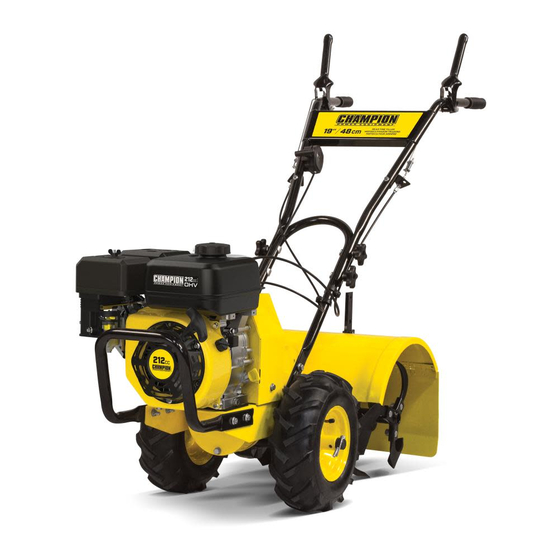
REAR TiNE TiLLER
or visit championpowerequipment.com
Champion Power Equipment, Inc., Santa Fe Springs, CA USA
MODEL #100380
Advertisement
Table of Contents

Related Manuals for Champion Power Equipment 100380


Summary of Contents for Champion Power Equipment 100380
- Page 1 Failure to do so could result in serious injury. This manual should remain with the product. Specifications, descriptions and illustrations in this manual are as accurate as known at the time of publication, but are subject to change without notice. Made in China - REV 20180123 Champion Power Equipment, Inc., Santa Fe Springs, CA USA...
-
Page 2: Table Of Contents
TAbLE Of CONTENTS 100380 - REAR TiNE TiLLER TAbLE Of CONTENTS Tilling Tips and Techniques ..... . Tilling Depths ........... -
Page 3: Introduction
100380 - REAR TiNE TiLLER iNTRODUCTiON SAfETY DEfiNiTiONS Congratulations on your purchase of a Champion Power The purpose of safety symbols is to attract your attention to Equipment (CPE) product. CPE designs, builds, and supports possible dangers. The safety symbols, and their explanations, all of our products to strict specifications and guidelines. -
Page 4: Important Safety Instructions
SAfETY iNSTRUCTiONS 100380 - REAR TiNE TiLLER iMPORTANT SAfETY iNSTRUCTiONS 6c. Keep matches, cigarettes, cigars, pipes, open flames and sparks away from the fuel tank and fuel container. WARNiNG 6d. Fill fuel tank outdoors with extreme care. Never fill fuel tank indoors. -
Page 5: Maintenance And Storage
SAfETY iNSTRUCTiONS 100380 - REAR TiNE TiLLER 14. Never operate the tiller under engine power if the 25. Never pull the tiller towards you. wheels are in the Freewheel position. In the Freewheel 26. Start the engine carefully according to instructions and position, the wheels will not hold the tiller back and the with feet well away from the tines. -
Page 6: Fuel Safety
SAfETY iNSTRUCTiONS 100380 - REAR TiNE TiLLER fuel Safety When transporting or servicing the tiller: Make certain that the fuel valve is in the OFF position and the DANGER gasoline tank is empty. GaSOLINE aND GaSOLINE VaPORS aRE hIGhLY Disconnect the spark plug wire. -
Page 7: Safety Symbols
SAfETY iNSTRUCTiONS 100380 - REAR TiNE TiLLER Safety Symbols Some of the following symbols may be used on this product. Please study them and learn their meaning. Proper interpretation of these symbols will allow you to more safely operate the product. - Page 8 SAfETY iNSTRUCTiONS 100380 - REAR TiNE TiLLER SYmBOL mEaNING Toxic Fumes. The engine exhaust from this product contains chemicals known to cause cancer, birth defects and other reproductive harm. Risk of asphyxiation. This engine emits carbon monoxide, an odorless, colorless poison gas.
-
Page 9: Operation Symbols
SAfETY iNSTRUCTiONS 100380 - REAR TiNE TiLLER Operation Symbols Some of the following symbols may be used on this product. Please study them and learn their meaning. Proper interpretation of these symbols will allow you to more safely operate the product. -
Page 10: Safety Labels
85. Maximum 10 % d'éthanol. This artwork belongs to Champion Power Equipment. The contents are confidential and privileged and shall not be disclosed to or used by or for outside parties without the explicit consent of Champion Power Equipment. -
Page 11: Safety Labels
B: updated French per CTC 100493 review Safety Icons This artwork belongs to Champion Power Equipment. The contents are confidential and privileged and shall not be disclosed to or used by or for outside parties without the explicit consent of Champion Power Equipment. -
Page 12: Controls And Features
CONTROLS AND fEATURES 100380 - REAR TiNE TiLLER CONTROLS AND fEATURES Read this operator’s manual before operating your tiller. Familiarize yourself with the location and function of the controls and features. Save this manual for future reference. 10 11 Tiller Engine 1. - Page 13 CONTROLS AND fEATURES 100380 - REAR TiNE TiLLER Parts included accessories Engine Oil (0.6 qt.) ..............1 Oil Funnel ................1 Tools Included 8–10 Wrench ................. 1 12–14 Wrench ............... 1 13–16 Wrench ............... 1 Spark Plug Wrench (engine) ........... 1 Tools Not Included Needle Nose Pliers (for cotter pins) ........
-
Page 14: Assembly
ASSEMbLY 100380 - REAR TiNE TiLLER ASSEMbLY Your tiller requires some assembly. This unit ships from our factory without oil. It must be properly serviced with fuel and oil before operation. If you have any questions regarding the assembly of your tiller, call our Technical Support Team at 1-877-338-0999. -
Page 15: Install The Tine Shield
ASSEMbLY 100380 - REAR TiNE TiLLER install the Tine Shield 2. Insert the (4) M8×50 curved head bolts into the holes as shown and securely with the (4) handle knobs and (4) flat 1. Remove the (4) M10×25 mm flange head bolts installed in washers. -
Page 16: Introduction
ASSEMbLY 100380 - REAR TiNE TiLLER To replace the wheels in the WhEEL DRIVE or FREEWhEEL: 1. Stop the engine, disconnect the spark plug wire from the spark plug and allow engine to cool. 2. Raise one wheel about 1 in. (2.5 cm) off the ground and place a sturdy support under the transmission. -
Page 17: Forward Lever
ASSEMbLY 100380 - REAR TiNE TiLLER 3. Depress and hold the lever against the handlebar to start WARNiNG the wheels in reverse and tines rotating in a forward Before starting engine, be sure that both wheels are direction. in WHEEL DRIVE position. See Wheel Drive Pins for 4. -
Page 18: Handlebar Height Adjustment
OPERATiON 100380 - REAR TiNE TiLLER OPERATiON WARNiNG Before operating your machine, carefully read and understand all safety, controls and operating instructions in this Operator’s Manual. Failure to follow these instructions can result in serious personal injury introduction Read this section before you start the engine. Then, take the... -
Page 19: Add Engine Oil
OPERATiON 100380 - REAR TiNE TiLLER 3. Remove oil fill cap/dipstick to add engine oil. CAUTiON 4. Using a funnel, add up to 0.6 qt. (0.6 L) of oil and replace Use regular unleaded gasoline with a minimum octane oil fill cap/dipstick. -
Page 20: Stopping The Engine And The Tiller
OPERATiON 100380 - REAR TiNE TiLLER WARNiNG Keep away from rotating tines. Rotating tines will cause injury. 1. Make certain the tiller is on a flat, level surface. 2. Put the wheels in the WHEEL DRIVE position (wheel pins must be through holes in wheel hubs and wheel shaft). -
Page 21: Operation At High Altitude
TiLLiNG TiPS AND TECHNiqUES 100380 - REAR TiNE TiLLER 2. Turn the fuel valve to the “OFF” position. In order to select the correct high altitude main jet it is necessary to identify the carburetor model. For this purpose, a code is stamped on the side of the carburetor. Select the correct high altitude jet part number corresponding to the carburetor code found on your particular carburetor. -
Page 22: Choosing Correct Wheel And Tine Speeds
TiLLiNG TiPS AND TECHNiqUES 100380 - REAR TiNE TiLLER Tilling on Slopes When cultivating (breaking up surface soil around plants to destroy weeds), adjust the tines to dig only 1 in. to 2 in. (2.5 Read the following recommendations before tilling on slopes: to 5 cm) deep. -
Page 23: Clearing The Tines
TiLLiNG TiPS AND TECHNiqUES 100380 - REAR TiNE TiLLER Loading and Unloading the Tiller – Terraces should be only 2-to-3 ft. (60-90 cm) wide. Digging too far into the side of the slope will expose poor subsoil that is unproductive for plants. -
Page 24: Maintenance
MAiNTENANCE 100380 - REAR TiNE TiLLER MAiNTENANCE EVERY 3 mONThS OR EVERY 50 hOURS OF OPERaTION — Change engine oil WARNiNG — Replace reduction gear oil Before inspecting, cleaning or servicing the machine, shut — Replace air filter element off engine, wait for all moving parts to come to a complete —... -
Page 25: Check For Oil Leaks
MAiNTENANCE 100380 - REAR TiNE TiLLER Check for Oil Leaks Before each use, check the tiller for signs of an oil leak — usually a dirty, oily accumulation either on the unit or on the floor. A little seepage around a cover or an oil seal is usually not a cause for alarm. -
Page 26: Tines
MAiNTENANCE 100380 - REAR TiNE TiLLER Tines The tines will wear with use and should be inspected at the beginning of each tilling season and after every 30 operating hours. The tines can be replaced either individually or as a complete set. -
Page 27: Belt Tension Adjustment
MAiNTENANCE 100380 - REAR TiNE TiLLER Replacement Belt Information REVERSE LEVER If the drive belt needs to be replaced, refer to the parts list for information. The procedure requires average mechanical ability and commonly available tools to change or replace. -
Page 28: Change Forward/Reverse Belts
MAiNTENANCE 100380 - REAR TiNE TiLLER Change forward/Reverse belts a. Remove the two forward belt guide studs and forward belt idler assembly. 1. Turn off engine. Engine must cool completely before proceeding. 2. Remove spark plug wire and secure away from spark plug. -
Page 29: Engine Cleaning
MAiNTENANCE 100380 - REAR TiNE TiLLER 9. Tighten the forward and reverse lower jam nut. 10. Check the belt tension. The belts should be loose with the REVERSE bELT iDLER drive levers disengaged. 11. Replace the upper and lower belt guards. - Page 30 MAiNTENANCE 100380 - REAR TiNE TiLLER 3. Clean around the oil dipstick to prevent dirt from falling into the crankcase. 4. On engines with a dipstick, remove it and wipe it clean. Reinsert the dipstick, tighten it securely, and remove it.
-
Page 31: Air Cleaner Maintenance
TRANSPORTATiON AND STORAGE 100380 - REAR TiNE TiLLER 5. Measure the spark plug clearance with a spark plug gap NOTiCE gauge. The clearance should be 0.7-0.8 mm. If adjustment is necessary, bend the side electrode carefully. Weather will affect engine oil and engine performance. -
Page 32: Off-Season Storage
TRANSPORTATiON AND STORAGE 100380 - REAR TiNE TiLLER Off-Season Storage Removing from Storage When the tiller won’t be used for an extended period, prepare it 1 mONTh for storage as follows: — No repair needed. 1. Make sure the storage area is dry and free of dust. -
Page 33: Specifications
SPECifiCATiONS 100380 - REAR TiNE TiLLER SPECifiCATiONS Tiller Specifications Model ............ 100380 Tine Diameter ....... .. -
Page 34: Parts Diagram
SPECifiCATiONS 100380 - REAR TiNE TiLLER Parts Diagram... - Page 35 SPECifiCATiONS 100380 - REAR TiNE TiLLER...
- Page 36 SPECifiCATiONS 100380 - REAR TiNE TiLLER...
- Page 37 SPECifiCATiONS 100380 - REAR TiNE TiLLER...
-
Page 38: Parts List
SPECifiCATiONS 100380 - REAR TiNE TiLLER Parts List Part Number Description Qty. Part Number Description Qty. Handle Bar Knob Nut 38 100380-027 Pin Roll Ø6 × 16 100380-001 39 100380-028 Shaft Bushing 1 Fan-shaped Screw 100380-002 M8 × 50 Flat Washer 40 100379-057 Ø8 ×... - Page 39 SPECifiCATiONS 100380 - REAR TiNE TiLLER Part Number Description Qty. Part Number Description Qty. 75 100380-056 Tension Wheel Pole 110 100380-084 Adjusting Shim 76 100380-057 111 100380-085 Belt Block Set 1 Lock Pin 77 100380-058 Spring Washer Ø6 Wheel, Left, 13inch, 112 100380-086.48...
- Page 40 SPECifiCATiONS 100380 - REAR TiNE TiLLER Part Number Description Qty. Flange Bolt M6 × 35, 146 100380-110.2 Black Flange Locknut M6, 147 100380-111.2 Black...
-
Page 41: Engine Parts Diagram
SPECifiCATiONS 100380 - REAR TiNE TiLLER Engine Parts Diagram... -
Page 42: Engine Parts List
SPECifiCATiONS 100380 - REAR TiNE TiLLER Engine Parts List Part Number Description Qty. Part Number Description Qty. 31 13300-Z533210-0000 12131-Z950110-0000 Gasket, Cylinder Head Crankshaft Assembly 32 13200-Z140210-0099 Piston Ring Assembly Cover Subassembly, 12410-Z440110-0099 Cylinder Head 33 13122-Z010110-0000 Clip, Piston Pin... - Page 43 SPECifiCATiONS 100380 - REAR TiNE TiLLER Part Number Description Qty. Air Cleaner Assembly, 68 17100-Z010210-0000 Black 69 17150-Z010110-0000 Element, Air Cleaner 70 18001-Z440110-0000 Gasket, Exhaust Outlet 71 90303-0800-31 Nut, M8 Muffler Assembly, 72 18100-Z012410-H300 Black 73 16620-Z440410-H600 Fuel Tank, Black...
-
Page 44: Troubleshooting
TROUbLESHOOTiNG 100380 - REAR TiNE TiLLER TROUbLESHOOTiNG Problem Cause Solution Spark plug wire disconnected. Reconnect wire. Engine Throttle Control Lever incorrectly Put lever in START position. set. Fuel tank empty. Add fuel. Choke control (if so equipped) in Move to CHOKE position. -
Page 45: Difficulty Starting Engine (Recoil)
TROUbLESHOOTiNG 100380 - REAR TiNE TiLLER Difficulty Starting Engine (Recoil) Problem Cause Solution There is no enough fuel in fuel tank and Fill fuel, open fuel cock. fuel cock is closed. Air vent in the fuel filler cap is clogged. -
Page 46: Gasoline Engine: No Power
TROUbLESHOOTiNG 100380 - REAR TiNE TiLLER Gasoline Engine: No Power Problem Cause Solution Air in fuel line or fuel line clogged. Exhaust air or dredge fuel line. Main oil flow hole is not adjusted Readjust. properly. In carburetor, needle valve hole and Clean and blow to clear. -
Page 47: Stops Suddenly When Running
TROUbLESHOOTiNG 100380 - REAR TiNE TiLLER Stops Suddenly When Running Problem Cause Solution Fuel is empty. Refill fuel. Carburetor is clogged. Check fuel line and dredge. Float is leaking. Repair. Needle valve is stuck. Dismantle float chamber and eliminate. Spark plug is punctured, or short- Replace spark plug. -
Page 48: Technical Service
Warranty Qualifications – Failures due to acts of God and other force majeure events Champion Power Equipment (CPE) will register this warranty upon beyond the manufacturer’s control. receipt of your Warranty Registration Card and a copy of your sales –... - Page 49 The United States Environment Protection Agency (U.S. EPA.) and the California Air Resources Board (CARB) Emission Control System Warranty Your Champion Power Equipment (CPE) engine complies with both the U.S. EPA and state of California Air Resources Board (CARB) emission regulations.
- Page 50 EMISSION CONTROL SYSTEM WARRANTY The following are specific provisions relative to your Emission Control System (ECS) Warranty Coverage. 1. APPLICABILITY: This warranty shall apply to 1995 and later model year California small off-road engines (SORE) (for other states, 1997 and later model year engines). The ECS Warranty Period shall begin on the date the new engine or equipment is delivered to its original, end-use purchaser, and shall continue for 24 consecutive months thereafter.
- Page 51 You must take your CPE engine or the product on which it is installed, along with your warranty registration card or other proof of original purchase date, at your expense, to any Champion Power Equipment dealer who is authorized by Champion Power Equipment, Inc. to sell and service that CPE product during his normal business hours.
- Page 52 Champion Power Equipment, Inc (CPE) and Environment and Climate Change Canada (ECCC) Emission Control System Warranty Your Champion Power Equipment (CPE) engine complies with Environment and Climate Change Canada (ECCC) emission regulations. YOUR WARRANTY RIGHTS AND OBLIGATIONS: CPE is pleased to explain the Emission Control Systems Warranty on your 2018 small off-road engine (SORE).
- Page 53 EMISSION CONTROL SYSTEM WARRANTY The following are specific provisions relative to your Emission Control System Warranty Coverage. Emission Control System Warranty (ECS Warranty): 1. APPLICABILITY: The ECS Warranty Period shall begin on the date the new engine or equipment is delivered to its original, end-use purchaser, and shall continue for 24 consecutive months thereafter.
- Page 54 Champion Power Equipment dealer who is authorized by Champion Power Equipment, Inc. to sell and service that CPE product during his normal business hours. Claims for repair or adjustment found to be caused solely by defects in material or workmanship will not be denied because the engine was not properly maintained and used.
Need help?
Do you have a question about the 100380 and is the answer not in the manual?
Questions and answers
i need the following part, 100380-43. where can I order it?