Intermatic PE24VA Operation & Service Manual
Suitable for pool / spa equipment applications
Hide thumbs
Also See for PE24VA:
- Installation manual (50 pages) ,
- Installation, operation & service manual (6 pages)
Table of Contents
Advertisement
Quick Links
Download this manual
See also:
Installation Manual
POOL/SPA CONTROL
ACCESSORIES
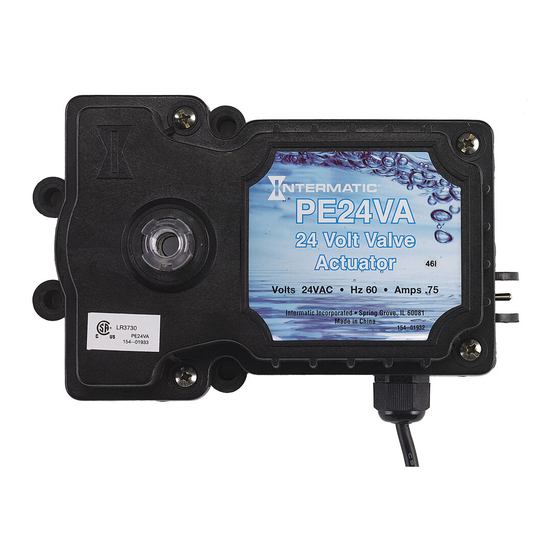
MODEL PE24VA VALVE ACTUATOR
Suitable for Pool / SPA Equipment Applications
ELECTRICAL RATINGS: 24 Volts, 60 Hz, 0.75 Amps.
Normal Operation Duty Cycle: 1 minute ON (Max), 8 minutes OFF (Min). These values
may be temporarily exceeded during installation testing and adjustment.
WARNING
•
TO BE CONNECTED TO A CLASS 2 CIRCUIT ONLY
•
ALL WIRING MUST COMPLY WITH ALL STATE AND LOCAL ELECTRICAL CODES INCLUDING THE
NATIONAL ELECTRICAL CODE AND/OR CANADIAN ELECTRICAL CODE.
1. Unscrew the hold-down knob and remove handle from valve
shaft. Set aside the knob and handle for later use.
2. With a Phillips screwdriver, remove the four screws from the
valve body as shown in Figure 1.
3. Turn the actuator over and observe the teeth as shown in
Figure 2.
4. Place the actuator over the valve shaft so the small tooth
engages with the small slot in the valve shaft. See Figure 2.
5. Rotate the actuator until the actuator posts line up with the four
holes so it matches one of the mounting positions shown in
Figure 3. See table below for descriptions of mounting options.
Mounting Options
Standard Plumbing - A three-port valve is the port B (middle) being
the incoming (common) port and A and C ports are the outlet ports
(see Figure 1).
Standard Actuator Mounting - The main body of the actuator is
over port B as shown in Item II of Figure 3.
The actuator can also be mounted on top of a valve in four different
positions as shown in Figure 3. Depending on the plumbing of the
valve and mounting position of the actuator, the cams inside the
actuator may have to be reset. (See next section.)
6. Use the supplied four long stainless steel screws to attach the
actuator to the valve.
7. Use the hold-down knob set aside in step 1 to connect the
handle to the valve shaft.
8. Connect power supply cord to a CLASS 2 CIRCUIT ONLY,
rated 24V nominal, 4A or 100VA maximum.
Risk of Electrical Shock
READ, FOLLOW & SAVE THIS INSTRUCTION MANUAL
MOUNTING ACTUATOR ON TOP OF VALVE
INSTALLATION
OPERATION &
SERVICE MANUAL
Port A
Port B
Water flows into or
(Common Port)
out of the valve
Figure 1. Standard Plumbing
Place actuator on valve so small tooth aligns
with small slot.
SMALL SLOT
SMALL TOOTH
VALVE
Figure 2. Actuator Mounting
ITEM I
Port A
Port B (Common Port)
ITEM III
Figure 3. Mounting Positions
Screws (4)
Port C
BOTTOM
VIEW OF
ACTUATOR
ITEM II
Port C
ITEM IV
Advertisement
Table of Contents

Related Manuals for Intermatic PE24VA


Summary of Contents for Intermatic PE24VA
- Page 1 OPERATION & POOL/SPA CONTROL SERVICE MANUAL ACCESSORIES MODEL PE24VA VALVE ACTUATOR Suitable for Pool / SPA Equipment Applications ELECTRICAL RATINGS: 24 Volts, 60 Hz, 0.75 Amps. Normal Operation Duty Cycle: 1 minute ON (Max), 8 minutes OFF (Min). These values may be temporarily exceeded during installation testing and adjustment.
- Page 2 RESETTING THE CAMS 1. Determine the COMMON and EXIT port(s) of the valve. 2. Remove the four screws and actuator lid to locate the cam/ Push Down to motor compartment. See Figure 4 to observe the cam. Loosen Star Rotate Locking Ring 3.
- Page 3 OPERATION During the normal operating season, the valves may need to be rotated manually, such as draining or filling the pool/spa. The valves can be rotated electrically or manually. If the system has power, rotate electrically. If no power, rotate manually. Rotating Valve Actuator Electrically 1.
- Page 4 ONE YEAR LIMITED WARRANTY If within the warranty period specified, this product fails due to a defect in material or workmanship, Intermatic Incorporated will repair or replace it, at its sole option, free of charge. This warranty is extended to the original household purchaser only and is not transferable. This warranty does not apply to: (a) damage to units caused by accident, dropping or abuse in handling, acts of God, or any negligent use;...
Need help?
Do you have a question about the PE24VA and is the answer not in the manual?
Questions and answers