
Related Manuals for YOKOGAWA UT750


Summary of Contents for YOKOGAWA UT750
- Page 1 Instruction Manual Model UT750 Digital Indicating Controller User’s Manual for Single-loop Control IM 05D01B02-41E IM 05D01B02-41E 1st Edition...
- Page 2 Blank Page...
- Page 3 User Setting column, where you can record your setpoints when setting them in the controller. I Controllers Applicable to Single-loop Control The specification codes of the UT750 applicable to single-loop control are given in the table below. UT750-00...
- Page 4 Draws attention to information that is essential for understanding the operation and/or features of the controller. I Regarding Force Majeure Yokogawa M&C Corporation assumes no liability for any loss or damage, direct or indirect, caused by the use of or unpredictable defects of the product. IM 05D01B02-41E...
-
Page 5: Table Of Contents
Toc-1 <Int> <Rev> Model UT750 Digital Indicating Controller User’s Manual for Single-loop Control IM 05D01B02-41E 1st Edition CONTENTS Installation ....................1-1 Model and Suffix Codes .................. 1-1 How to Install ....................1-2 How to Connect Wires ..................1-5 Hardware Specifications ................1-7 Terminal Wiring Diagrams ................ - Page 6 Toc-2 <Int> <Rev> Troubleshooting and Maintenance ............4-1 Troubleshooting ....................4-1 Maintenance ....................4-5 4.2.1 Cleaning ................... 4-5 4.2.2 Replacing Brackets ................4-5 4.2.3 Attaching Terminal Cover ..............4-5 4.2.4 Replacing Parts with a Limited Service Life ........4-7 4.2.5 Replacing Control Output Relays ............
-
Page 7: Installation
Model and Suffix Codes Before using the controller, check that the model and suffix codes match your order. Model Suffix Code Description UT750 Digital indicating controller (provided with Custom Computing Function*) Single-loop type Type Position proportional type Dual-loop type... -
Page 8: How To Install
<Toc> <1. Installation> How to Install NOTE To install the controller, select a location where: no one may accidentally touch the terminals, mechanical vibrations are minimal, 150mm corrosive gas is minimal, temperature can be maintained at about 23 C and 150mm 150mm the fluctuation is minimal,... - Page 9 <Toc> <1. Installation> I External Dimensions and Panel Cutout Dimensions Unit: mm UT750 Large bracket REM1 REM2 MAN1 MAN2 SET/ENT DISP Small bracket (Panel thickness) 1 to 10 mm General installation Side-by-side close installation +0.8 117 min. [(N-1) 96+92] (53) 145 min.
- Page 10 <Toc> <1. Installation> I How to Install Turn off the power to the controller before installing it on the panel because there is a possibility of electric shock. CAUTION After opening the mounting hole on the panel, follow the procedures below to install the controller: Insert the controller into the opening from the front of the panel so that the terminal board on the rear is at the far side.
-
Page 11: How To Connect Wires
I For DC Relay Wiring I For AC Relay Wiring UT750 UT750 External AC power supply External DC power supply... - Page 12 Power supply, grounding, relay contact outputs 600 V PVC insulated wires, JIS C 3307, 0.9 to 2.0 mm Thermocouple Shielded compensating lead wires, JIS C 1610, (See Yokogawa Electric’s GS 6B1U1-E.) Shielded wires (three conductors), UL2482 (Hitachi Cable) Other signals Shielded wires...
-
Page 13: Hardware Specifications
<Toc> <1. Installation> Hardware Specifications PV Input Signals • Number of inputs: 1 (terminals • Input type: Universal input system. The input type can be selected with the software. • Sampling period: 50, 100, 200 and 500 ms (The sampling period can be selected with the software.) Initial value;... - Page 14 <Toc> <1. Installation> Feedback Resistance Input Provided for position proportional type only (terminals • Slide resistance value: 100 to 2.5 k of overall resistance (burnout detection for sliding wire provided) • Measuring resolution: 0.1% of overall resistance Loop Power Supply Power is supplied to a two-wire transmitter.
- Page 15 • Transistor contact rating: 24 V DC, 50 mA (COM terminal is common) Display Specifications • PV display: 5-digit, 7-segment, red LEDs, character height of 20 mm for UT750 • Setpoint display: 32 128 dot LCD display with back-light • Status indicating lamps: LEDs Safety and EMC Standards •...
- Page 16 1-10 <Toc> <1. Installation> Construction, Installation, and Wiring • Construction: Only the front panel is dust-proof and drip-proof (protection class IP55) For side-by-side close installation the controller loses its dust-proof and drip-proof protection. • Material: ABS resin and polycarbonate • Case color: Black •...
- Page 17 1-11 <Toc> <1. Installation> Signal Isolations • PV input terminals: Isolated from other input/output terminals. Not isolated from the internal circuit. • Remote input terminals: Isolated from other input/output terminals and the internal circuit. • 15 V DC loop power supply terminals: Not isolated from analog current output and voltage pulse control output.
- Page 18 1-12 <Toc> <1. Installation> Environmental Conditions • Normal operating conditions: Ambient temperature: 0 to 50 C (40 C or less for side-by-side close installation) Temperature change rate: 10 C/h or less Ambient humidity: 20 to 90% RH (no condensation allowed) Magnetic field: 400 A/m or less Continuous vibration at 5 to 14 Hz: Full amplitude of 1.2 mm or less Continuous vibration at 14 to 150 Hz: 4.9 m/s...
-
Page 19: Terminal Wiring Diagrams
1-13 <Toc> <1. Installation> Terminal Wiring Diagrams NOTE Do not use unassigned terminals as relay terminals. Terminal wiring diagrams are shown on and after the next page. IM 05D01B02-41E 1st Edition : May 31,2000-00... -
Page 23: Initial Settings
<Toc> <2. Initial Settings> Initial Settings This chapter describes examples of setting PV input types, control output types, and alarm types. Carrying out settings described herein allows you to perform basic control. Refer to examples of various settings to understand how to set parameters required. -
Page 24: Names And Functions Of Front Panel Parts
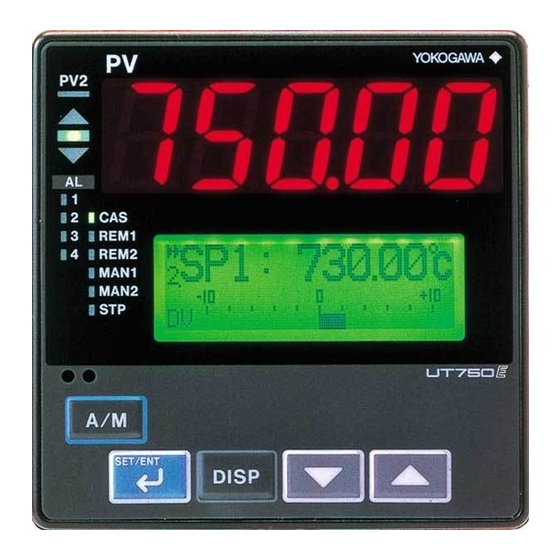
<Toc> <2. Initial Settings> Names and Functions of Front Panel Parts 1. Indicator lamp for display of PV2 6.Process variable (PV) display 2. Deviation monitor 4. Alarm indicator 7.Setpoint lamps REM1 display REM2 MAN1 3. Status indicator MAN2 lamps 10.DISP key 5. -
Page 25: Setting Pv Input Type (Setting First At Power-On)
<Toc> <2. Initial Settings> Setting PV Input Type (Setting First at Power-on) NOTE • The controller displays an operating display when the power is turned on. The submenu “IN” appears at this point if the type of PV input has not been defined yet. In this case, first press the key once to display the parameter “IN1”... - Page 26 <Toc> <2. Initial Settings> The following operating procedure describes an example of setting a K-type thermocouple (-200.0 to 500.0 C) and a measurement range of 0.0 to 200.0 C. Display view at power-on The PV display in the figure below shows the error code for input burnout ( ) if PV input wiring is not yet complete.
- Page 27 <Toc> <2. Initial Settings> Press the SET/ENT key once to register the Press the SET/ENT key once to register the setpoint. setpoint. MENU:UTMD/IN MENU:UTMD/IN input 1 range high input 1 range low SETUP SETUP 200.0 SET/ENT SET/ENT DISP DISP If the type of input is voltage, also config- Press the SET/ENT key once to display the...
- Page 28 <Toc> <2. Initial Settings> I Instrument Input Range Codes Instrument Input Instrument Input Type Measurement Accuracy Range Code Input Range Set the data item PV Input Type “IN1” to the OFF option to leave the PV input Unspecified OFF (0) type undefined.
- Page 29 <Toc> <2. Initial Settings> NOTE The controller may automatically initialize the registered operating parameter setpoints if any change is made to the data item PV Input Type (IN1), Maximum Value of PV Input Range (RH1), Minimum Value of PV Input Range (RL1), PV Input Decimal Point Position (SDP1), Maximum Value of PV Input Scale (SH1) or Minimum Value of PV Input Scale (SL1).
-
Page 30: Changing Pv Input Type
Press the key once to display the main SET/ENT to call up the main menu “MODE”. menu “UTMD”. MODE UTMD mode parameter UT750 configuration main menu SETUP main menu SET/ENT SET/ENT DISP DISP Press the key once to display the main... - Page 31 <Toc> <2. Initial Settings> Press the SET/ENT key once to display the Press the key to display the parameter “IN1” (PV input type). required setpoint. The figure below shows an example of setting the maximum value MENU:UTMD/IN of the PV input range to 200.0 C. input 1 type select SETUP typeK3...
-
Page 32: Setting Control Output Type (Except For A Position Proportional Controller)
2-10 <Toc> <2. Initial Settings> Press the SET/ENT key once to register the Press the SET/ENT key for more than 3 seconds. setpoint. This returns you to the display shown at power-on (figure below). MENU:UTMD/IN input 1 range low SETUP SP : 0.0°C SET/ENT... - Page 33 Press the key to display the menu “UTMD”. required setpoint. The figure below shows an example of setting to current output (4 UTMD to 20 mA DC). UT750 configuration SETUP main menu MENU:UTMD/OUT output 1 select changing SET/ENT Blinks during DISP change.
- Page 34 2-12 <Toc> <2. Initial Settings> G List of Control Output Types Parameter Name of Parameter Setpoint Control Output Types Symbol Time proportional PID relay contact output (terminals Time proportional PID voltage pulse output (terminals Current output (terminals On/off control relay contact output (terminals Heating-side relay output (terminals ), cooling-side relay output (terminals Heating-side pulse output (terminals...
-
Page 35: Calibrating Valve Position (For A Position Proportional Controller Only)
3 seconds Press the key once to display the main to call up the main menu “MODE”. menu “UTMD”. MODE UTMD mode parameter UT750 configuration main menu SETUP main menu SET/ENT SET/ENT DISP DISP Press the... - Page 36 2-14 <Toc> <2. Initial Settings> Press the SET/ENT key once to display the The controller is viewed as shown below parameter “V.AT”. when the valve position is being automati- cally calibrated. MENU:UTMD/VALV valve auto tuning MENU:UTMD/VALV SETUP valve auto tuning V.AT V.AT SET/ENT...
-
Page 37: Initializing Parameters
3 seconds Press the key once to display the main to call up the main menu “MODE”. menu “UTMD”. MODE UTMD mode parameter UT750 configuration main menu SETUP main menu SET/ENT SET/ENT DISP DISP Press the... -
Page 38: Changing Alarm Type
2-16 <Toc> <2. Initial Settings> Press the SET/ENT key once to display the Press the SET/ENT key once. The display parameter “INI”. momentarily becomes blank (which is normal), indicating the parameters have MENU:UTMD/INIT been initialized. parameter initialize SETUP MENU:UTMD/INIT parameter initialize SETUP SET/ENT DISP... - Page 39 2-17 <Toc> <2. Initial Settings> Press the SET/ENT key for more than 3 seconds Press the SET/ENT key once to display the to call up the main menu “MODE”. parameter “AL1” (alarm-1 type). MENU:LOOP1/ALM MODE alarm 1 type select mode parameter SETUP main menu SET/ENT...
- Page 40 2-18 <Toc> <2. Initial Settings> I List of Alarm Types The table below shows the alarm types and alarm actions. In the table, codes 1 to 10 are not provided with stand-by actions, while codes 11 to 20 are provided with stand-by actions. Alarm type code Alarm type code Alarm action...
-
Page 41: Description Of Multiple Setpoints And Pid
Power-on Description of Multiple Setpoints and PID The UT750 has a maximum of eight target setpoints, and has PID for each of these setpoints. The following shows the correspondence between the target setpoint numbers (SPNO), target setpoints (SP), and PID parameters. - Page 42 Blank Page...
-
Page 43: Operations
<Toc> <3. Operations> Operations This chapter describes key entries for operating the controller. For operations using external contact inputs, see “1.5 Terminal Wiring Diagrams.” If you cannot remem- ber how to carry out an operation during setting, press the key no more than DISP four times. - Page 44 <Toc> <3. Operations> SP : 100.0°C SP display Allows the target setpoint to be changed. Press the key to change the setpoint and press the SET/ENT key to register it. DISP °C 1.SP = 100.0 PID:1 OUT = 30.0 % OUT display Allows the control output value to be changed in manual operation.
- Page 45 <Toc> <3. Operations> I Operating Displays for Single-loop Heating/Cooling Control G SP Display The target setpoint (SP), along with the deviation bar appears on the Setpoint display (LCD). G Heating/Cooling OUT Display The target setpoint, PID number, and heating-side (HEAT) and cooling-side (COOL) control output values appears on the Setpoint display (LCD).
-
Page 46: Setting Target Setpoint (Sp)
<Toc> <3. Operations> Setting Target Setpoint (SP) The following operating procedure describes an example of setting 150.0 to a target setpoint. In automatic operation, the controller starts control using set target setpoints. Bring the operating display into view (display appears at power on). Displays target setpoint-1 Displays PV. -
Page 47: Performing/Canceling Auto-Tuning
<Toc> <3. Operations> Performing/Canceling Auto-tuning Auto-tuning should be carried out after setting a target setpoint (SP). Make sure the con- troller is in automatic operation mode (AUTO) and in running state (RUN) before carrying out auto-tuning. See “3.8 Switching between AUTO and MAN,” to change to AUTO and “3.7 Switching between Run and Stop,”... - Page 48 <Toc> <3. Operations> Press the key to display the Press the SET/ENT key once to register the required setpoint. Tuning for 1.SP is AT = 1. setpoint. (This starts auto-tuning.) To cancel auto-tuning, set AT = OFF. If the key is pressed when AT = OFF, SET/ENT auto-tuning will be cancelled.
-
Page 49: Setting Pid Manually
<Toc> <3. Operations> Setting PID Manually If you know the values to be set or if suitable PID constants cannot be obtained by auto- tuning, follow the procedure below to set values. Bring the operating display into view (display appears at power on) Displays target setpoint-1 Displays PV. -
Page 50: Setting Alarm Setpoints
<Toc> <3. Operations> [TIP] Press the SET/ENT key once to register the For the PID parameter number you set in setpoint. step 5, select: the submenu “1.PID” if the PID con- MENU:LP1/1.PID proportional band stants are for 1.SP; 18.0% the submenu “2.PID” if the PID con- stants are for 2.SP;... - Page 51 <Toc> <3. Operations> Press the SET/ENT key for more than 3 seconds Press the SET/ENT key twice to display the to call up the main menu “MODE”. parameter “1.A1”. MENU:LP1/1.PID MODE alarm-1 set point mode parameter main menu 1.A1 200.0°C SET/ENT SET/ENT DISP...
-
Page 52: Selecting Target Setpoint Numbers (Spno)
3-10 <Toc> <3. Operations> Selecting Target Setpoint Numbers (SPNO) The following operating procedure describes an example of changing a target setpoint number (SPNO) from 1 to 2. NOTE If a target setpoint number has been switched using contact input, when the contact input is on, that number cannot be selected by keystroke. -
Page 53: Switching Between Run And Stop
3-11 <Toc> <3. Operations> Switching between Run and Stop Selection between the Run state (RUN) and Stop state (STOP) can be made with contact input 6 (DI6). “RUN” when DI6 is set to OFF REM1 REM2 MAN1 MAN2 SET/ENT DISP “STOP”... -
Page 54: Switching Between Auto And Man
3-12 <Toc> <3. Operations> Switching between AUTO and MAN NOTE If AUTO and MAN have been switched using contact input, when the contact input is ON, switching between AUTO and MAN cannot be achieved by keystroke. Bring the operating display into view (display appears at power on). Displays Displays PV. -
Page 55: Manipulating Control Output During Manual Operation
3-13 <Toc> <3. Operations> Manipulating Control Output during Manual Operation NOTE Control output cannot be changed if the controller is stopped. In this case, the preset output value (operating parameter PO) will be output. A control output value is linked with a display value changed using the key. - Page 56 3-14 <Toc> <3. Operations> G Controller Behavior and Control Output Manipulation when the Dead Band is Positive The following is an example when the DB parameter is set at 12.4%. If you hold down the key with the heating-side output under manipulation (i.e., cooling- side output C = 0.0%), the heating-side output (H =) decreases.
-
Page 57: Switching Between Remote (Rem) And Local (Lcl)
3-15 <Toc> <3. Operations> I Manipulating the Control Output during Position Proportional Control The controller continues to provide control output as long as the key is being pressed. key: Closes the valve. key: Opens the valve. REM1 REM2 MAN1 MAN2 MAN1 lamp SET/ENT DISP... - Page 58 3-16 <Toc> <3. Operations> Bring the operating display into view (display appears at power on). Displays Displays PV. target setpoint-1 “1.SP”. REM1 REM2 MAN1 MAN2 SP : 100.0°C REM1 lamp OFF. SET/ENT DISP In steps 2 and later, illustrations of the LCD are cited to explain the procedure. Press the SET/ENT key for more than 3 seconds...
-
Page 59: Troubleshooting And Maintenance
<Toc> <4. Troubleshooting and Maintenance> Troubleshooting and Maintenance Troubleshooting I Troubleshooting Flow If the operating display does not appear after turning on the controller’s power, follow the measures in the procedure below. If a problem appears complicated, contact our sales representative. Is the instrument defective? Is key... - Page 60 <Toc> <4. Troubleshooting and Maintenance> I Errors at Power on The following table shows errors that may be detected by the fault diagnosis function when the power is turned on. Display Description Control Alarm Retransmission Error indication Communication Remedy position of error output output...
- Page 61 <Toc> <4. Troubleshooting and Maintenance> I Possible Errors during Operation The following shows possible errors occurring during operations. Display position Description Alarm Retransmis- Commu- Error indication Control output Remedy (Note) of error output sion output nication Displays “RJC” and Measured RJC error Normal action PV alternately...
- Page 62 G The Controller does not Show the Correct Process Variable (PV). • The UT750 controllers have a universal input. The type of PV input can be set/changed using the parameter “IN1”. At this point, the controller must be wired correctly according to the selected type of PV input.
-
Page 63: Maintenance
<Toc> <4. Troubleshooting and Maintenance> Maintenance This section describes the cleaning and maintenance of the UT750. 4.2.1 Cleaning The front panel and operation keys should be gently wiped with a dry cloth. NOTE Do not use alcohol, benzine, or any other solvents. - Page 64 <Toc> <4. Troubleshooting and Maintenance> I Attaching Terminal Cover The procedure for attaching the terminal cover is as follows. Do not touch the terminals on the rear panel when power is being supplied to the controller. Doing so may result in electric shock. Before attaching the terminal cover, turn off the source circuit breaker and use a tester to CAUTION check that the power cable is not conducting any electricity.
-
Page 65: Replacing Parts With A Limited Service Life
<Toc> <4. Troubleshooting and Maintenance> 4.2.4 Replacing Parts with a Limited Service Life The following UT750 parts have a limited service life. The service life given in the table assume that the controller is used under normal operating conditions. Part... -
Page 66: Replacing Control Output Relays
<Toc> <4. Troubleshooting and Maintenance> 4.2.5 Replacing Control Output Relays This subsection describes how to replace the control output relays. The replacement must be performed by an engineer qualified for the work. Always turn off the power before starting the work in order to avoid electric shock. Do not pull out the internal unit for any other purpose other than to replace the control output relays. - Page 67 (Note) Be careful not to damage the RJC sensor. The location and number of the relays differ depending on the model code of the UT750. Confirm the location of the control output relay to be replaced before pulling out the relay.
- Page 68 4-10 <Toc> <4. Troubleshooting and Maintenance> Pull out the relay to be replaced. The control output relays are easy to remove and mount, since they are connected via a socket onto the print boards. Insert the new relay in the socket. Use the following relay. Manufacturer OMRON Model...
-
Page 69: Parameters
<5. Parameters> Parameters Parameter Map This section contains “Operating Parameter Map” and “Setup Parameter Map” for UT750 as a guideline for setting parameters. These maps are helpful in finding the positions of the displays when setting the param- eters, and should be used as a quick reference for the entire range of parameter displays. - Page 70 <Toc> <5. Parameters> UT750 Operating Parameter Map Operating Display DISP Operating Operating Operating Operating (Note) display 1 display 2 display 3 display n SET3S SET1S SET3S Main menu DISP DISP SELECT display 1 MODE SELECT DISP submenu display 2 SELECT display 3 1.PID...
- Page 71 1.PMD 2.PMD Note: The number of operating displays and the contents of such displays differ according to the UT750 models, UT modes and control output types. SELECT displays 1 to 5 are shown only when they are registered. *7 Main menu USR is displayed when UT mode is “Loop control with PV switching,” “Loop control with PV auto-selector,”...
- Page 72 <Toc> <5. Parameters> UT750 Setup Parameter Map Password To operating parameter setting check display display main menu [MODE] (on the previous page) Main menu DISP LOOP1 LOOP2 CMLP submenu DISP DISP DISP TRND LOCK A.BS1 RET1 DVB1 A.FL1 RTH1 DVB2 A.SR1...
- Page 73 Note: The parameter items shown on the [TEST] submenu of the setup parameter setting display are to be used by Yokogawa service personnel to check the controller functions. User cannot set or change these parameters. *4 Submenu R485 is displayed only for the controller with communication function.
-
Page 74: Lists Of Parameters
<Toc> <5. Parameters> Lists of Parameters This section describes the functions of parameters briefly. In addition, each parameter table has a “User Setting” column, where you can record your setpoints when setting them in the controller. * Parameters relating to PV or setpoints should all be set in real numbers. For example, use temperature values to define target setpoints and alarm setpoints for temperature input. - Page 75 <Toc> <5. Parameters> G Operation-related Parameters Located in: Main menu = ; Submenu = Parameter Name of Parameter Setting Range and Description Initial Value User Target Item Symbol Setting in CD-ROM Auto-tuning OFF (0): No auto-tuning OFF (0) 1: Auto-tuning for 1.SP 2: Auto-tuning for 2.SP 3: Auto-tuning for 3.SP 4: Auto-tuning for 4.SP...
- Page 76 <Toc> <5. Parameters> G Setpoint-, Alarm- and PID-related Parameters 1.PID Located in: Main menu = ; Submenu = The table below lists the Target Setpoint-1 (1.SP) operating parameter and parameters that apply to the 1.SP parameter. Parameter Name of Parameter Setting Range and Description Initial Value User...
- Page 77 <Toc> <5. Parameters> Parameter Name of Parameter Setting Range and Description Initial Value User Target Item Symbol Setting in CD-ROM Cooling-side 0.0 to 999.9% 5.0% 1.Pc proportional band (Cooling-side ON/OFF control applies when 0.0) Cooling-side integral OFF (0), 1 to 6000 sec. 240 sec.
- Page 78 5-10 <Toc> <5. Parameters> G Ten-segment Linearizer 1 Parameters PYS1 Located in: Main menu = • Ten-segment linearizer biasing (factory-set default) Correction (Actual input + Ten- segment linearizer biasing) Actual input 1.b6 Ten-segment linearizer 1.b5 biasing 1.b3 1.b4 Ten-segment 1.a1 1.a2 1.a3 1.a4 1.a5 1.a6 1.a8...
- Page 79 5-11 <Toc> <5. Parameters> Parameter Name of Parameter Setting Range and Description Initial Value User Target Item Symbol Setting in CD-ROM 0.0% of PV input range Ten-segment -66.7% to 105.0% of PV input range 1.a1 linearizer 1 input-1 0.0% of PV input range span 0.0% of Ten-segment -66.7% to 105.0% of PV input range span 1.b1...
- Page 80 5-12 <Toc> <5. Parameters> I Setup Parameters G Target Setpoint-related Parameters LOOP1 Located in: Main menu = ; Submenu = Parameter Name of Parameter Setting Range and Description Initial Value User Target Item Symbol Setting in CD-ROM Remote input RSP (0): Uses the value set remotely via remote input (terminals). RSP (0) Ref.1.2(1) selection...
- Page 81 5-13 <Toc> <5. Parameters> G Alarm-related Parameters LOOP1 Located in: Main menu = ; Submenu = Parameter Name of Parameter Setting Range and Description Initial Value User Target Item Symbol Setting in CD-ROM Alarm-1 type OFF (0), 1 to 31 Ref.3.3(3) (same as below) Ref.3.3(4)
- Page 82 5-14 <Toc> <5. Parameters> Parameter Name of Parameter Setting Range and Description Initial Value User Target Item Symbol Setting in CD-ROM Zone PID selection 0: SP selection 1: Zone PID If set to “SP selection,” allows PID constants to be selected for each Ref.4.1(2) target setpoint.
- Page 83 5-15 <Toc> <5. Parameters> G Analog Input Computation Parameters CMLP Located in: Main menu = ; Submenu = Parameter Name of Parameter Setting Range and Description Initial Value User Target Item Symbol Setting in CD-ROM 0.0% of PV Analog input-1 bias Used to correct the PV input value beforehand.
- Page 84 5-16 <Toc> <5. Parameters> G Retransmission Output Parameters CMLP Located in: Main menu = ; Submenu = Parameter Name of Parameter Setting Range and Description Initial Value User Target Item Symbol Setting in CD-ROM Retransmission OFF (0): Disable RET1 output-1 type 1: PV1, 2: SP1, 3: OUT1, 4: LPS loop power supply (15 V), 5: PV2, 6: SP2, 7: OUT2 Setpoints 5 to 7 are not available for single-loop control.
- Page 85 5-17 <Toc> <5. Parameters> G Security-related Parameters CMLP LOCK Located in: Main menu = ; Submenu = Parameter Name of Parameter Setting Range and Description Initial Value User Target Item Symbol Setting in CD-ROM OFF (0) Front panel data setting OFF (0): Unlock ( , ) key lock ON (1): Lock...
- Page 86 5-18 <Toc> <5. Parameters> G Contact Output Registration Parameters CONF Located in: Main menu = ; Submenu = Parameter Name of Parameter Setting Range and Description Initial Value User Target Item Symbol Setting in CD-ROM 5689 Relay output flag The following setpoints are registration numbers for Single-loop registration for DO1 Control only.
- Page 87 5-19 <Toc> <5. Parameters> G UT Mode Parameters UTMD Located in: Main menu = ; Submenu = Parameter Name of Parameter Setting Range and Description Initial Value User Target Item Symbol Setting in CD-ROM Controller mode 1: Single-loop Control (UT mode) For another controller mode, see User’s Manual (Reference) (CD-ROM version).
- Page 88 5-20 <Toc> <5. Parameters> Parameter Name of Parameter Setting Range and Description Initial Value User Target Item Symbol Setting in CD-ROM Although not used in Single-loop Control, it is shown on the display. UNI2 Although not used in Single-loop Control, it is shown on the display. Although not used in Single-loop Control, it is shown on the display.
- Page 89 5-21 <Toc> <5. Parameters> G Output-related Parameters UTMD Located in: Main menu = ; Submenu = Parameter Name of Parameter Setting Range and Description Initial User Target Item Symbol Value Setting in CD-ROM Control output Time proportional PID relay contact output (terminals type Time proportional PID voltage pulse output (terminals Current output (terminals...
- Page 90 5-22 <Toc> <5. Parameters> I Performing Split Computations [V-mode Output] The following explains an example of letting “Analog OUTPUT-1 (terminals )” and “Analog OUTPUT-3 (terminals )” present the V-mode characteristics of split computations. Set the Control Output Type (OT1) parameter to “2”. This sets the control output to “current output.”...
- Page 91 5-23 <Toc> <5. Parameters> [Parallel-mode Output] The following explains an example of letting “Analog OUTPUT-1 (terminals )” and “Analog OUTPUT-3 (terminals )” present the parallel-mode characteristics of split computations. Set the Control Output Type (OT1) parameter to “2”. This sets the control output to “current output.” Set the Retransmission Output 1 (RET1) parameter to “3”.
- Page 92 5-24 <Toc> <5. Parameters> G Communication Parameters UTMD R485 Located in: Main menu = ; Submenu = Parameter Name of Parameter Setting Range and Description Initial Value User Target Item Symbol Setting in CD-ROM Protocol selection-1 0: PC link communication PSL1 1: PC link communication (with sum check) 2: Ladder communication...
- Page 93 5-25 <Toc> <5. Parameters> G Value Calibration Related Parameters (Displayed for Position Proportional Controllers) UTMD VALV Located in: Main menu = ; Submenu = Parameter Name of Parameter Setting Range and Description Initial Value User Target Item Symbol Setting in CD-ROM Automatic valve Automatically adjusts the fully-closed and fully-opened OFF (0)
- Page 94 5-26 <Toc> <5. Parameters> I Tips about Heating/Cooling Control In heating/cooling control, the controller outputs the result of computation after splitting it into heating-purpose and cooling-purpose signals. In addition, the controller can perform PID control or ON/OFF control on the heating and cooling sides separately. When perform- ing ON/OFF control, set the proportional band to “0”.
- Page 95 5-27 <Toc> <5. Parameters> I Tips about Position Proportional Control (for position proportional con- trollers only) Position proportional control can be of either feedback type or estimating type. In feedback-type position proportional control, the controller obtains a valve position signal from a feedback slide-wire resistor attached to a valve.
- Page 96 Blank Page...
-
Page 97: Function Block Diagram And Descriptions
<Toc> <6. Function Block Diagram and Descriptions> Function Block Diagram and Descriptions This chapter contains the function block diagrams for “Single-loop control,” “Single-loop heating/cooling control,” and “Single-loop position proportional con- trol.” For details on these function block diagrams, refer to the descriptions men- tioned later. - Page 98 <Toc> <6. Function Block Diagram and Descriptions> I Function Block Diagram for Single-loop Control Communication PV input Remote input terminals terminals terminals Contact input INPUT1 INPUT3 RS485 Input selection Input selection Unit selection Unit selection Analog input range conversion Analog input range conversion Analog input bias Analog input bias Square root extraction...
- Page 99 <Toc> <6. Function Block Diagram and Descriptions> I Function Block Diagram for Single-loop Heating/Cooling Control Communication PV input Remote input terminals terminals terminals Contact input INPUT1 INPUT3 RS485 Input selection Input selection Unit selection Unit selection Analog input range conversion Analog input range conversion Analog input bias Analog input bias...
- Page 100 <Toc> <6. Function Block Diagram and Descriptions> I Function Block Diagram for Single-loop Position Proportional Control Communication PV input Remote input terminals terminals terminals Contact input INPUT1 INPUT3 RS485 Input selection Input selection Unit selection Unit selection Analog input range conversion Analog input range conversion Analog input bias Analog input bias...
- Page 101 <Toc> <6. Function Block Diagram and Descriptions> Functions and Parameters for “Single-loop Control” in Initial State (Fac- tory-set default) Functions and parameters in initial state are given in the tables below. For details on each parameter, refer to “5.2 Lists of Parameters.” I PV Input PV input (INPUT1) is a universal input, which can receive signals from thermocouple, RTD, or DC voltage signals.
- Page 102 <Toc> <6. Function Block Diagram and Descriptions> I Remote Input Remote input (INPUT3) can receive DC voltage signals. The controller is capable of bias- ing, square root extraction, first-order lag computation (filtering), and ratio biasing on remote input signals. Each function can be set by the following parameters. Setup Parameters Function Parameter...
- Page 103 <Toc> <6. Function Block Diagram and Descriptions> I Target Setpoint and PID It is possible to use a maximum of eight groups of target setpoints and PID parameters. The target setpoint can be selected by key operation or contact input. For selection by contact input, refer to “Contact Input.”...
- Page 104 <Toc> <6. Function Block Diagram and Descriptions> I Control Output Control output (OUTPUT1) selects the output type among the current output, voltage pulse output, and relay contact output signal. Preset output value is output when the operation is stopped by key operation or contact input, which takes priority over the manual operation.
- Page 105 <Toc> <6. Function Block Diagram and Descriptions> Operating Parameters Function Parameter Main menu Submenu Alarm 1 setpoint n.A1 n.PID Alarm 2 setpoint n.A2 n.PID Alarm 3 setpoint n.A3 n.PID Alarm 4 setpoint n.A4 n.PID Note: Submenu n.PID (n=1 to 8) corresponds to the target setpoint number selected in the target setpoint number selection (SPNO).
- Page 106 Blank Page...
- Page 107 <Int> <Toc> Revision Information G Title : Model UT750 Digital Indicating Controller User’s Manual for Single-loop Control G Manual No. : IM 05D01B02-41E May 2000/1st Edition Newly published Written by Products Documents Controllers & Conditioners Division Yokogawa M&C Corporation Published by Yokogawa M&C Corporation...
- Page 108 Blank Page...
Need help?
Do you have a question about the UT750 and is the answer not in the manual?
Questions and answers