Table of Contents
Advertisement
Quick Links
UVX Radiometer
Instruction Guide
UVP, LLC
Ultra-Violet Products Ltd.
2066 W. 11th Street
Unit 1, Trinity Hall Farm Estate
Upland, CA 91786
Nuffield Road, Cambridge CB4 1TG UK
Phone: (800) 452-6788
Phone: +44(0)1223-420022
Fax: (909) 946-3597
Fax: +44(0)1223-420561
Web Site: www.uvp.com
81-0064-01 Rev L
Advertisement
Table of Contents

Summary of Contents for UVP UVX
- Page 1 UVX Radiometer Instruction Guide UVP, LLC Ultra-Violet Products Ltd. 2066 W. 11th Street Unit 1, Trinity Hall Farm Estate Upland, CA 91786 Nuffield Road, Cambridge CB4 1TG UK Phone: (800) 452-6788 Phone: +44(0)1223-420022 Fax: (909) 946-3597 Fax: +44(0)1223-420561 Web Site: www.uvp.com...
-
Page 2: Table Of Contents
UVX Radiometer Table of Contents General Instructions ............................5 Introduction ..............................5 Features..............................5 Specifications ............................6 Operating Procedures ..........................6 Radiometer Details ............................9 Circuit Description ............................. 9 Radiometer Circuit Calibration ........................9 Radiometer Maintenance ........................10 Sensor Details ............................. 16 Sensor Characteristics .......................... - Page 3 Figure 16: Continuous Emitter, 285nm Phosphor Coated UV Lamp ............26 Figure 17: Example, Illustrating Why Sensor Field of View is Important When Measuring Irradiance ..28 Figure 18: Projected Area of Sensor ......................28 Figure 19: Cosine Response of Typical UVX Sensor (Polar Plot) .............. 29...
-
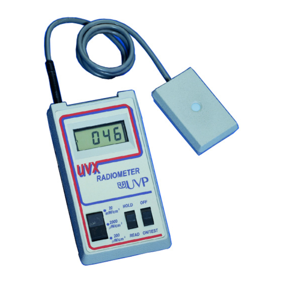
Page 4: Figure 1: Rear And Side Views Of Radiometer
UVX Radiometer Figure 1: Rear and Side Views of Radiometer... -
Page 5: General Instructions
NDT techniques, and graphics procedures. The UVX Series Sensor that is supplied with this unit, as well as all other UVX Series Sensors, is designed and calibrated for measurement of radiant incidences from line type and phosphor coated mercury arc sources. -
Page 6: Specifications
Then close the battery cover. • Plug the UVX sensor into the mating connector at the left rear of the UVX Radiometer. This receptacle is identified in Figure 1. Note: The connector goes through two "snap" positions before it is fully inserted. Failure to insert the... - Page 7 UVX Radiometer • Place the three position range switch in the 20 mW/cm2 position. Place the READ/HOLD switch in the READ position. • Turn the unit on by placing the OFF-ON/TEST switch in the ON/TEST position. Note: For the first one second of operation, the entire display will be turned on demonstrating that all segments, decimal points and colon of the display are functioning properly.
- Page 8 UVX Radiometer CAUTION Refer to the Safety Precautions section of this manual before making ultraviolet measurements with this radiometer. If, when the sensor has been placed in the UV radiant incident field, all the digits are blanked except for the leading 1, an overrange condition is indicated.
-
Page 9: Radiometer Details
Radiometer Circuit Calibration This section refers to the calibration of the radiometer, not of the sensor. UVP recommends recalibration of the radiometer every 6 months. UVP provides calibration services for a nominal fee. Contact the factory for details. Note: Should the user attempt to perform a calibration on the radiometer prior to the end of the warranty period, then the warranty on the radiometer becomes void. -
Page 10: Radiometer Maintenance
Care of Radiometer Case The case of the UVX Radiometer is fabricated from a durable ABS plastic. As with all plastics, solvents should not be used for cleaning of the case. A high quality plastic cleaner or mild soap and water should be used to clean fingerprints, dust of dirt from the case. - Page 11 UVX Radiometer output are recessed and should not require attention. Troubleshooting Procedures In the event the radiometer malfunctions, the following procedures will enable the user to determine the source of error and affect repairs. If, in the following procedures, any of the active circuit elements are replaced, then the calibration procedure must be performed prior to putting the radiometer back into service.
- Page 12 During that time the test mode condition should be displayed on the readout. If the display shows the test mode correctly, then the malfunction is in the ON/TEST switch and the unit must be returned to UVP for repair. If it is not, then integrated circuit A2 is malfunctioning and must be replaced.
- Page 13 UVX sensor. Note: For direct traceability to NIST standards, the sensor must be returned to UVP for repair and recalibration. Refer to the section in the manual on Sensor Details.
-
Page 14: Figure 2: Radiometer Functional Block Diagram
UVX Radiometer Figure 2: Radiometer Functional Block Diagram Figure 3: Radiometer Circuit Board (Component Location) -
Page 15: Figure 4: Calibration Current Source
UVX Radiometer Figure 4: Calibration Current Source Figure 5: LCD Display Pin-outs... -
Page 16: Sensor Details
0.1% per mW-hcm Spectral Response Curves Figures 7, 8 and 9 show the typical spectral response characteristics of the UVX 25, 31 and 36 Series Sensors (respectively). In each case the absolute response curve is typical. Individual sensors may exhibit variations in response at wavelengths distant from the calibration wavelength, but all are accurately calibrated to a response of 1.00 at the specified calibration wavelength. -
Page 17: Figure 6: Uvx-25 Sensor Solarization Curve
UVX Radiometer Figure 6: UVX-25 Sensor Solarization Curve Figure 7: Typical UVX-25 Sensor Spectral Response... -
Page 18: Figure 8: Typical Uvx-31 Sensor Spectral Response
UVX Radiometer Figure 8: Typical UVX-31 Sensor Spectral Response Figure 9: Typical UVX-36 Sensor Spectral Response... -
Page 19: Figure 10: Typical Sensor Response Versus Incidence Angle
Standards and Technology (NIST) standard of spectral irradiance. This calibration is performed at UVP calibrations laboratory a minimum of once every six months. The NIST standard of spectral irradiance used by UVP is a 1000 watt tungsten lamp. This lamp is replaced after every 20 hours of operation. -
Page 20: Sensor Maintenance
Care of Sensor Case CAUTION: Do not use abrasive cleaners on any part of the UVX Series Sensors or allow water to get inside the sensor. The case of the UVX sensors is fabricated from a durable ABS plastic. As with all plastics, solvents should not be used in cleaning of the case. -
Page 21: Figure 11: Schematic Of Uvx Series Sensor
UVX Radiometer Figure 11: Schematic of UVX Series Sensor Figure 12: Measurement of Irradiance... -
Page 22: Figure 13: Typical Output From Low Pressure Mercury Lamp
UVX Radiometer Figure 13: Typical Output From Low Pressure Mercury Lamp... -
Page 23: Application Techniques
One is that negligible radiation, other than the 254nm wavelength, occurs within the sensitivity wavelength region of the UVX-25 sensor. The second is that the sensor is calibrated to yield a correct measurement for 254nm light. Thus, the radiometer system yields an accurate measurement of irradiance. - Page 24 UVX Radiometer UVP manufactures other sensors which are also calibrated using line sources at other wavelengths. The user must take special precautions when using "line source calibrated sensors" to measure irradiance from lamps radiating at wavelengths other than those for which the sensor was calibrated. A common application of this type occurs when measuring irradiance from phosphor coated lamps which emit continuously over a broad wavelength region.
-
Page 25: Figure 14: Hypothetical Light Source Having An Output At 270Nm Wavelength
UVX Radiometer Figure 14: Hypothetical Light Source Having an Output at 270nm Wavelength Figure 15: Response of Three Sensors Calibrated to Yield the Same Output at 254nm Wavelength... -
Page 26: Cosine Response
The Polar Plot in Figure 19 has been drawn from the curve of Figure 10 to show how the UVX sensor compares to the perfect cosine response. The sensor is identified by the broken curve in the figure. The solid curve, also shown, identifies a perfect cosine response. -
Page 27: Safety Precautions
For low exposures, this preventive method may be the only protection necessary. The UVX Radiometer system is capable of measuring radiant incidence levels which are extremely hazardous to unprotected personnel. In these cases (see recommended reading above), full face shields... -
Page 28: Figure 17: Example, Illustrating Why Sensor Field Of View Is Important When Measuring Irradiance
UVX Radiometer Figure 17: Example, Illustrating Why Sensor Field of View is Important When Measuring Irradiance Figure 18: Projected Area of Sensor... -
Page 29: Figure 19: Cosine Response Of Typical Uvx Sensor (Polar Plot)
UVX Radiometer Figure 19: Cosine Response of Typical UVX Sensor (Polar Plot) -
Page 30: Component List, Replacement Parts, And Options
Component List The following list is the components used on the printed circuit board assembly P/N 57-0005-04. PART NO. DESCRIPTION COMPONENT DESIGNATION 57-0005-01 Printed Circuit Board, UVX Radiometer 57-0041-10 Resistor, 4.99K, 1/8W, 1% 50-0041-21 Resistor, 536 ohms, 1/8W, 1% 50-0041-22... -
Page 31: Replacement Parts
51-0031-01 Liquid Crystal Display (D1 ) Note: There are no replacement parts for the UVX sensors. In case of damage or malfunction, the sensor must be returned to UVP for repair and recalibration. Options A number of options are available for use with the UVX Radiometer. These options expand the functions of the UVX as well as provide greater user application and adaptability to specific requirements. -
Page 32: Warranty
Moreover, UVP makes no warranties whatsoever with respect to parts not supplied by UVP or that have been installed, used and/or serviced other than in strict compliance with the instructions appearing in the operational manual supplied to the end user.
Need help?
Do you have a question about the UVX and is the answer not in the manual?
Questions and answers