Table of Contents
Advertisement
Quick Links
See also:
User Manual
g
Application
These kits provide the wiring and switches required for a
Power Break circuit breaker to use power management
trip unit features. The kit catalog numbers are TPSP for
800–2000 A stationary breakers, TCSP for 800–2000 A
Draw-Out Breakers, TPLP for 2500–4000 A stationary
breakers, and TCLP for 2500–4000 A draw-out breakers.
The parts included in these kits are listed in Table 1,
Table 2, Table 3, and Table 4.
The numbers in brackets in the following instructions and
figures refer to the item numbers in these tables.
Item
Part No.
1
10086637G1 Terminal board assembly
2
N701P1708B6 Thread-forming screw,
3
286A8112P1 Barrier (not used)
4
567B262G36 Auxiliary switch
5
793A765P2
6
793A765P3
Table 1. List of parts in the power management upgrade kits for 800–
2000 A stationary breakers, catalog number TPSP.
Item
Part No.
1
10086637G1 Terminal board assembly
2
N701P1708B6 Thread-forming screw,
3
286A8112P1 Barrier
4
567B262G42 Auxiliary switch
5
793A765P2
6
793A765P3
Table 2. List of parts in the power management upgrade kits for 2500–
4000 A stationary breakers, catalog number TPLP.
Item
Part No.
1
10086523G1
2
N701P1708B6
4
567B262G36 Auxiliary switch
5
793A765P2
6
793A765P3
7
N722P16006B6
8
TDOSVD907F Trip unit disconnect, breaker
9
TDOSVD12
10
Incl. with [9]
Table 3. List of parts in the power management upgrade kit for 800–
2000 A draw-out breakers, catalog number TCSP.
Description
1
#10-16 x
/
2
Wire tie, small
Wire tie, large
Description
#10-16 x
1
/
2
Wire tie, small
Wire tie, large
Description
Terminal board assembly
Thread-forming screw,
1
#10-16 x
/
2
Wire tie, small
Wire tie, large
Thread-forming screw,
#10-32 x
3
/
8
Trip unit disconnect,
substructure
Spring
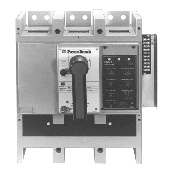
DEH40391 Installation Instructions
Power Break
Circuit Breakers
®
Power Management Upgrade
Item
Part No.
1
10086637G1
2
N701P1708B6
3
286A8112P1
4
567B262G42 Auxiliary Switch
5
793A765P2
6
793A765P3
7
N722P16006B6
8
TDOSVD907F Trip unit disconnect, breaker
9
TDOSVD12
Qty.
1
10
Incl. with [9]
2
Table 4. List of parts in the power management upgrade kit for 2500–
4000 A draw-out breakers, catalog number TCLP.
1
Installation
1
6
8
WARNING: Before beginning this procedure,
turn the breaker
voltage sources, and discharge the closing
springs.
Qty.
1
AVERTISSEMENT: Mettre le disjoncteur à
2
le débrancher de toutes les sources de tension et
déclencher les ressorts de fermeture avant
d'entamer cette procédure.
1
1
6
Preparing the Breaker
8
1. Turn the breaker off and discharge the closing
springs. Verify that the breaker indicator shows
2. Remove the breaker from its cubicle or substructure
and place it on a suitable working surface.
Qty.
3. Remove the cover from the breaker according to the
1
instructions in GEH-4693 (800–2000 A applications)
or GEH-4694 (2500–4000 A applications).
2
4. On draw-out breakers, remove the side plate on the
1
side with the terminal board.
6
8
Installing the Kit
2
5. Disconnect the leads to the terminal board and
bracket assembly, shown in Figure 1.
1
6. Remove the two screws securing the terminal board
1
and bracket assembly to the breaker, then remove the
1
old terminal board. On 2500–4000 A breakers, also
remove the fiber insulation barrier.
Description
Terminal board assembly
Thread-forming screw,
#10-16 x
1
/
2
Barrier
Wire tie, small
Wire tie, large
Thread-forming screw,
#10-32 x
3
/
8
Trip unit disconnect,
substructure
Spring
, disconnect it from all
OFF
R01
Qty.
1
4
1
1
6
8
2
1
1
1
,
OFF
OFF
.
Advertisement
Table of Contents

Related Manuals for GE Power Break


Summary of Contents for GE Power Break
- Page 1 Description Qty. These kits provide the wiring and switches required for a 10086637G1 Terminal board assembly Power Break circuit breaker to use power management Thread-forming screw, N701P1708B6 trip unit features. The kit catalog numbers are TPSP for #10-16 x 800–2000 A stationary breakers, TCSP for 800–2000 A...
- Page 2 Mounting Screws Figure 1. Old terminal board mounted on the breaker (2500–4000 A shown). 7. Push in the locking lever on the side of the trip unit mounting plate and carefully lift off the trip unit. Figure 3. Trip unit mounting plate on a 2500–4000 A breaker. 8.
- Page 3 11. If an auxiliary switch is present, remove it as follows: Mounting • 800–2000 A breaker, Figure 7: Remove the two mounting screws. • 2500–4000 A breaker, Figure 8: Remove the bolt, lock washer, and flat washer securing it to the C phase contact assembly.
- Page 4 12. Install the new auxiliary switch [4] as follows: • 800–2000 A breaker: Insert the new switch into the breaker base and secure with the two screws [2] supplied, as shown in Figure 10. • 2500–4000 A breaker: Place the new switch over the C phase contact assembly and secure with the bolt, lock washer, and flat washer removed in the previous step, as shown in Figure 11.
- Page 5 16. Attach the new terminal board and bracket assembly [1] to the breaker as follows: Barrier [3] • 800–2000 A breaker: Secure the bracket with the Mounting two #10-16 screws [2] supplied, as shown in Figure Screws [2] 15 for a stationary breaker and in Figure 16 for a draw-out installation.
- Page 6 Trip Unit Mounting Plate Bend the Screw Slots Locking Figure 20. Bending the locking tabs to secure the trip unit plug to the Figure 21. Trip unit mounting slots in the B phase CT on 2500–4000 A mounting plate. breakers. 21.
- Page 7 Spring Mounting Hole Trip Unit Disconnect [8] Mounting Screws [7] Disconnect Spring Mounting Studs Anchor Tab Figure 25. Placing the trip unit disconnect [9] on the mounting studs on the substructure side panel. Figure 23. New trip unit disconnect [8] installed on the side plate of a 2500–4000 A breaker.
- Page 8 Should further information be desired or should particular problems arise that are not covered sufficiently for the purchaser’s purposes, the matter should be referred to the GE Company. GE Industrial Systems General Electric Company 41 Woodford Ave., Plainville, CT 06062 DEH40391 R01 0702 ©...
Need help?
Do you have a question about the Power Break and is the answer not in the manual?
Questions and answers