Advertisement
Table of Contents
- 1 Health Advice
- 2 Items Supplied
- 3 Getting Started
- 4 Checking/Adjusting the Rip Fence
- 5 The Fence Rail
- 6 Top Blade Guard
- 7 Operation
- 8 On/Off Safety Switch
- 9 Raising/Lowering the Blade
- 10 Tilting the Blade
- 11 Rip Fence Guide
- 12 Mitre Gauge
- 13 Maintenance
- 14 Environmental Protection
- 15 Adjusting the Riving Knife
- 16 Push Stick
- Download this manual
Advertisement
Table of Contents

Summary of Contents for Parker PTS-250
- Page 1 Original Instructions Original Instructions Original Instructions Original written in UK English...
- Page 3 Handling (1.7) VIBRATION allowing the machine to do the work. excessive physical WARNING: When using this machine the on any of the machines controls. operator can be exposed to high levels and stability, IMPORTANT of vibration transmitted to the hand and and the orientation of the machine For your own safety, please read these operating and safety arm.
- Page 4 (1.9) (1.10) SAFETY PRECAUTIONS The term “power tool” in the warnings refers INTENDED USE OF to your mains-operated (corded) power tool Symbol Description THIS POWER TOOL or battery-operated (cordless) power tool. (1.14) ELECTRICAL SAFETY Volts WARNING: This product is a table saw and (2.2) has been designed to be used with wood 1) General Power Tool Safety Warnings...
-
Page 5: Health Advice
current device (RCD) protected supply. (2.5) (2.6) tool operation, always wear safety goggles Use of an RCD reduces the risk of electric shock. 4) General Power Tool Safety Warnings 5) General Power Tool Safety Warnings or safety glasses with side shield or a full face [Power tool use and care]. -
Page 6: Items Supplied
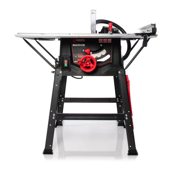
Never attempt to free a stalled blade Use proper extension cord. Make sure All operators using this machine must (4.2) any extension cord is in good condition. read the instructions and familiarize ITEMS SUPPLIED When using an extension cord, be sure to themselves with the machines workings. - Page 7 MACHINE OVERVIEW WHAT’S IN THE BOX K. MITRE GAUGE 1. ON/OFF SWITCH 7. RIP FENCE SCALE MAGNIFIER L. FENCE RAIL 2 pieces 2. RIVING KNIFE 8. RIP FENCE LOCKING HANDLE M. FENCE RAIL JOINING TONGUE D. REAR CANTILEVER BRACES N. HEX HEADED SCREW x 28 3.
- Page 8 ASSEMBLY Again only hand-tighten these screws at this stage. (C) to the corner legs (Fig. 5) in the same manner as the front and rear cross-braces Note: This process can be considerably aided by studying were attached. the images of an assembled machine as found on the machine overview page.
-
Page 9: Checking/Adjusting The Rip Fence
Insert the machine screw through the end of the support strut the raised saw blade. (Fig. 9) the rip fence the seven coach bolts (R) which hold the Use a straight edge or similar placed across the table and fence rail to the machine. the extension panel to check the alignment. -
Page 10: Top Blade Guard
TOP BLADE GUARD Note: The top blade guard is equipped with a dust extraction port (Fig.21). The top blade guard (H) (Fig. 18) (sometimes referred to as dust extraction hose to the top blade knife. The ‘split’ line along the top of the guard indicates the centre line of the saw blade below. -
Page 11: Tilting The Blade
When the hand-wheel is pushed in against its bias spring a Forwards and backwards adjustment of the rip fence faceplate cog engages with a curved toothed rack incorporated into the (Fig. 28) is possible. Loosen the two wing nuts and slide the aluminium faceplate to the desired position. - Page 12 Adjust to the required angle. Turn the handle clockwise CUTTING NARROW WORKPIECES to lock the mitre gauge at the chosen angle. (Fig. 32) Be sure to use a push stick (9) when making longitudinal Note: The extruded aluminium faceplate of the mitre gauge cuts in workpieces smaller than 120 mm in width.
-
Page 13: Maintenance
To set the rip fence for repetitive cross-cutting: the saw. The operators left hand will be to the LH side of the Set the rip fence at the required distance from the saw blade. saw blade. The operators right hand will be close to the rip Adjust and align the back of the rip fence faceplate with the fence on the RH side of the sawblade. -
Page 14: Environmental Protection
the spanners provided. Check that both blade are in (6.4) ENVIRONMENTAL PROTECTION contact with the blade. 3-5mm Replace the table access plate and its screw. Waste electrical products should not be disposed of Replace the top blade guard. with household waste. Please recycle where facilities exist. Check with your local authority or retailer for recycling advice.
Need help?
Do you have a question about the PTS-250 and is the answer not in the manual?
Questions and answers