Advertisement
Quick Links
Advertisement

Related Manuals for MTM 8-30


Summary of Contents for MTM 8-30
- Page 1 UNIVERSAL OIL HEATER TYP MTM 8-30 kW ORIGINAL MANUAL V. 08/2015...
-
Page 2: Ec Declaration Of Conformity
I hereby declare that the oil air heater intended for heating industrial rooms without central heating systems: model MTM 8-30, serial no.......... manufactured in the year 20…….. Rated power of 8-30 kW due to its design and structure, meets the basic safety and health requirements set forth in... -
Page 3: Technical Data
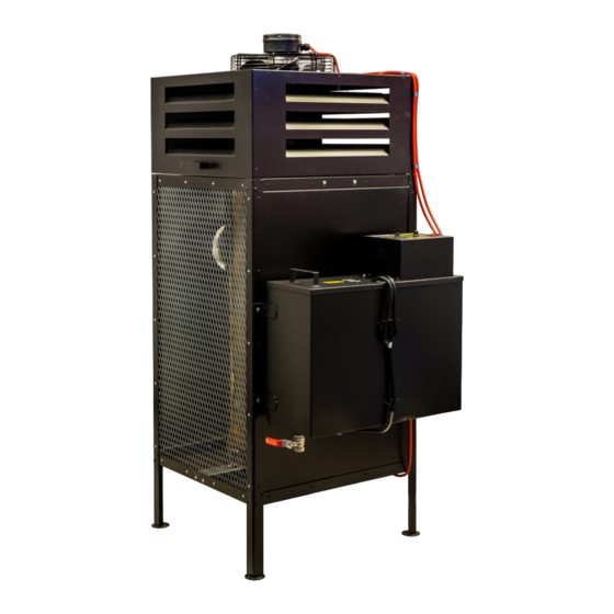
• preserving settings after blackout. 5. Safety aspects The MTM 8-30 universal oil heater is powered by the alternating current network of 230V/50Hz. It is equipped with three sensors, ensuring safe and economic operation of the device. 1. The bimetallic sensor, placed in the furnace chamber, reacts with short circuit of the contacts in the thermostat when the temperature exceeds 40°C and with contact opening when the temperature drops below... - Page 4 OF THE COMBUSTION CONTROLLER CHAMBER EXHAUST FUMES OUTLET FUEL TANK COMBUSTION CHAMBER FUEL FEEDING PUMP BURNER TROLLEY CONTROL OVERFLOW THERMOSTAT SENSOR Fig. 1. MTM 8-30 heater structure CONTROL THERMOSTAT FUEL PUMP MOTOR CONTROLLER OVERFLOW Fig. 2. MTM 8-30 heater block diagram.
- Page 5 7. Device installation familiarise with the local regulations, set the stove on a flat and hard ground, level the device, to provide optimal draught, install an at least 5-metre-long smooth, vertical stack pipe resistant high temperature (not aluminium), preferably made of stainless steel, check the tightness of all connections, tighten them with insulating tape, make sure the elements inside the combustion chamber are properly mounted and the burner is pushed to the end,...
- Page 6 CAUTION When installing the exhaust discharge system it is recommended to avoid horizontal sections of the stack pipe. In order to ensure free flow of gases, the angle of potential pipe bend should not exceed/be lower than 45°. The stack outlet must be above the roof top, preferably by ca. 1 m. The places where the stack penetrates the ceiling, walls or roof must be insulated in order to avoid fire hazard.
- Page 7 8. Description of device operation 8a. Control panel The MTM 8-30 type universal oil stove controller is equipped with the power setting knob, network switch and fuse socket. Fig. 5. Vide of the front control module panel. 8b. The operation of the device is characterised by the following statuses: •...
- Page 8 order return normal operation, wait until stove cooled down (i.e. the fan has switched off and the chamber is cooled down) and press the button on the casing of the bimetallic sensor (reset). Clean the chamber pan, taking into account that the pan and deflector can still be hot due to the fact that cast iron keeps temperature for a long time.
- Page 9 9b. Switching the device off In order to switch the device off and complete the heating process, turn the power setting knob on the control panel into the fan position and switch the button marked as MAINS to 0, causing the lamp to switch off.
- Page 10 10. Failure repair In case of device failure, the list provided below might help in locating in. Removal is usually simply. Potential problems are specified below. The numbers indicate the possible causes. The order of numbers shows the probability of failure. CAUTION: Unplug the device prior to commencement of any activities.
- Page 11 Servicing part diagram for MTM 8-30...
- Page 12 830.13 - FEEDING TUBE FOR THE COMBUSTION CHAMBER 830.14 - MTM 8-30 STOVE SWITCH 830.15 - FUSE SOCKET 830.16 - RUBBER GLAND 830.17 - ELECTRONIC PLATE TRANSFORMER OF THE MTM 8-30 STOVE 830.18 - CAPILLARY CONTROL THERMOSTAT 830.19 - FUEL DUCT T-PIPE 830.20 - COMBUSTION CHAMBER 830.21 FUEL PUMP FILTER...
Need help?
Do you have a question about the 8-30 and is the answer not in the manual?
Questions and answers