
Related Manuals for Hafco AL-320G


Summary of Contents for Hafco AL-320G
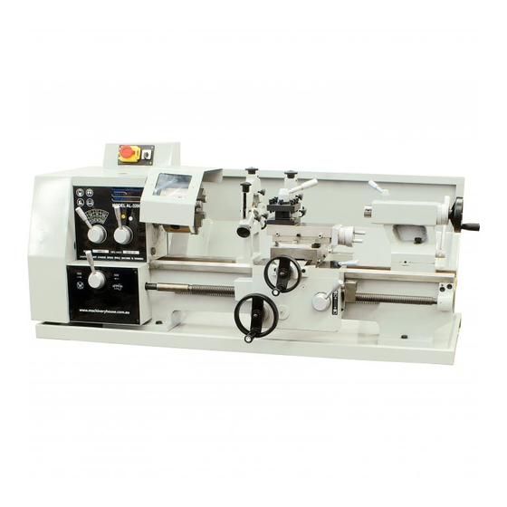
- Page 1 Page 1 Instructions Manual for AL-320G (L141) 07/02/2018 Metal Cutting Lathe OPERATION MANUAL Model AL-320G...
- Page 2 Page 2 Instructions Manual for AL-320G (L141) 07/02/2018 MACHINE DETAILS MACHINE METAL CUTTING LATHE MODEL NO. AL-320G SERIAL NO. DATE OF MANF. Distributed by www.machineryhouse.co.nz NOTE: This manual is only for your reference. Owing to the continuous improvement of the ma- chine, changes may be made at any time without obligation or notice.
-
Page 3: Table Of Contents
Page 3 Instructions Manual for AL-320G (L141) 07/02/2018 C O N T E N T S: Safety Precautions...............4 A. Overview of the Machine..........5 B. Main Usage and Features..........5 C. Main Specifications............6 D. Transmission System.............7 D.1 Main Transmission System........8 D.2 Feeding System............8 D.2.2 Threading..............9... -
Page 4: Safety Precautions
Page 4 Instructions Manual for AL-320G (L141) 07/02/2018 SAFETY PRECAUTIONS Safety glasses must be worn at Gloves must not be worn all times when using the lathe. when using this machine. Earmuffs should be worn Avoid wearing loose clothes, when noisy applications are... -
Page 5: Overview Of The Machine
Page 5 Instructions Manual for AL-320G (L141) 07/02/2018 A. OVERVIEW OF THE MACHINE 12. Tailstock Locking Lever 1. Gear Train Cover 2. Headstock 13. Main Switch 14. Forward-reverse Feeding Handle 3. Speed Changing Lever 4. Main Spindle 15. Feeding Box 16. -
Page 6: Main Specifications
Page 6 Instructions Manual for AL-320G (L141) 07/02/2018 C. MAIN SPECIFICATIONS MODEL AL-320 Centre Height 160mm Max. swing over bed 320mm Max. length of work piece 600/750mm MACHINE Max. swing over cross slide 170mm Headstock taper Spindle bore 38mm Spindle speed steps... -
Page 7: Transmission System
Page 7 Instructions Manual for AL-320G (L141) 07/02/2018 D. TRANSMISSION SYSTEM 1. Input Pulley 21. Half-nut for Longitudinal Lead Screw 2. Change Gear 22. Cross Slide Lead Screw 3. Change Gear 23. Cross Slide Lead Screw Nut 4. Change Gear 24. -
Page 8: Main Transmission System
Page 8 Instructions Manual for AL-320G (L141) 07/02/2018 D.1 Main Transmission System Power comes from the motor to the input shaft #37 via input pulley #1, From the input pulley to main spindle #40 via middle shaft #38. The main spindle has a range of 6 speeds by operating the speed changing handles on the head stock. -
Page 9: Threading
Page 9 Instructions Manual for AL-320G (L141) 07/02/2018 D.2.2 Threading When cutting threads, open the door to the change gear box, and check the change gear chart to select suitable gears to produce the threads required. (the change gears are standard acces- sories). -
Page 10: Thread Chart
Page 10 Instructions Manual for AL-320G (L141) 07/02/2018 Thread Chart... -
Page 11: D2.3 Setting The Cutting Tool With Spindle Centerline
Page 11 Instructions Manual for AL-320G (L141) 07/02/2018 4.7 SETTING THE CUTTING TOOL WITH SPINDLE CENTERLINE The tip of the cutting tool should be set up so that it is in line with the centre line of the spindle, as illustrated in Fig. 8. -
Page 12: Installation And Adjustment Of The Lathe
Page 12 Instructions Manual for AL-320G (L141) 07/02/2018 E. INSTALLATION AND ADJUSTMENT OF THE LATHE E.1 Installation When lifting the machine it is recommended that the method used in the diagram below is used or a fork lift is used. Since there is no obvious hand holding places, please do not lift or carry the lathe by hand. -
Page 13: Adjustment Of The Lathe
Page 13 Instructions Manual for AL-320G (L141) 07/02/2018 E.2 ADJUSTMENT OF THE LATHE E.2.1 Adjustment Of Main Spindle The main spindle has been adjusted correctly before leaving the factory and you are not re- quired to make any adjustment. However over the life of the machine it may be necessary to adjust the spindle to correct the bearing tolerance. -
Page 14: The Adjustment Of The Locking Handles Of The Tailstock
Page 14 Instructions Manual for AL-320G (L141) 07/02/2018 Two Screws and lock nuts Wedge Fig. 10 Two screws and lock nuts Wedge Wedge Fig. 11 Fig. 12 E.2.3 The Adjustment Of The Locking Handles Of The Tailstock Locking Handle Locking Nut Fig. -
Page 15: Operation
Page 15 Instructions Manual for AL-320G (L141) 07/02/2018 F. OPERATION After assembling the machine, remove the anti-corrosion coating on the slideway, carriage, toolpost, tailstock and change gears with a clean cloth and kerosene. Once the machine is clean lubricate the machine as per instructions. -
Page 16: Speed Changing Of The Main Spindle
Page 16 Instructions Manual for AL-320G (L141) 07/02/2018 F.2 Speed Changing Of The Main Spindle The speed change of the main spindle can be achieved by operating the two speed change handles on the headstock. The speed chart shows the positions of the motor pulley changes that are needed to achieve some range of speeds. -
Page 17: Lubrication Points
Page 17 Instructions Manual for AL-320G (L141) 07/02/2018 Lubrication Points Fig. 16 Table Of Lubrication Points... -
Page 18: Wiring Diagram
Page 18 Instructions Manual for AL-320G (L141) 07/02/2018 H. Wiring Diagram Fig. 17 The maintenance of the electrical parts, and wiring must be made by a qualified electrician. Wiring Colour Code. Yellow/Green wire --- Grounding Blue wire --- Neutral Brown --- Live Cautions: If the motor does not work while the power voltage is on, first check the cut-out units. -
Page 19: Spare Parts
Page 19 Instructions Manual for AL-320G (L141) 07/02/2018 SPARE PARTS SECTION The following section covers the spare parts diagrams and lists that were current at the time this manual was originally printed. Due to continuous improvements of the machine, changes may be made at any time without notification. -
Page 20: Al-320 Bed Parts
Page 20 Instructions Manual for AL-320G (L141) 07/02/2018 AL-320 BED PARTS... -
Page 21: Al-320 Bed Parts List
Page 21 Instructions Manual for AL-320G (L141) 07/02/2018 AL-320 BED PARTS LIST Part No. Description CQ9332-01-001 CQ9332-01-003 Racks 6x18 GB117-86 Taper pin M8x16 GB70-85 Hexagon socket cap head screws 5 GB97. 2-8.5 Washer M5x10 GB65-85 Screw CQ9332-01-005 Chuck 6 GB1155-79... - Page 22 Page 22 Instructions Manual for AL-320G (L141) 07/02/2018 AL-320 BED PARTS LIST Cont. Part No. Description CQ9332-01-009 Cross nut CQ9332-01-004 Middle carriage CQ9332-00-006 Shield CQ9332-01-002 Longitudinal feed screw CQ9332-01-006 Right pedestal 6 GB1155-79 Oil cup CQ9332-01-010 Sleeve CQ9332-02-011 Spigots M8x25 GB70-85...
-
Page 23: Al-320 Headstock Parts
Page 23 Instructions Manual for AL-320G (L141) 07/02/2018 AL-320 HEADSTOCK PARTS... -
Page 24: Al-320 Headstock Parts List
Page 24 Instructions Manual for AL-320G (L141) 07/02/2018 AL-320 HEADSTOCK PARTS LIST Part No. Description M161.5 GB812-88 Spanner nut 16 GB858-88 Lock washer for circular nut 16 GB97.2-85 Plain washers 5x16 GB1096-79 Plain parallel key CQ9332A-02-016 Spindle pulley 60206 GB298-89... - Page 25 Page 25 Instructions Manual for AL-320G (L141) 07/02/2018 AL-320 HEADSTOCK PARTS LIST Cont. Part No. Description 5x60 GB1096-79 Plain paralle key 20 GB894.1-86 External snap ring CQ9332-02-025 5x40 Gear GB1096-79 Plain paralle key CQ9332-02-028 Middle shaft 203 GB276-89 Single-row ball bearing...
- Page 26 Page 26 Instructions Manual for AL-320G (L141) 07/02/2018 AL-320 HEADSTOCK PARTS LIST Cont. Part No. Description 5x50 GB117-86 0.8x5x25 GB2089 -80 Spring 6 .5 GB308 -84 Steel ball M5x12 GB819- 85 Screw AT400-04-127 Locating sleeve 16x2.4 GB1235-76 0-seal ring CQ9332-02-035...
-
Page 27: Al-320 Back Gear Parts
Page 27 Instructions Manual for AL-320G (L141) 07/02/2018 AL-320 BACK GEARS PARTS... -
Page 28: Al-320 Back Gear Parts.list
Page 28 Instructions Manual for AL-320G (L141) 07/02/2018 AL-320 BACK GEARS PARTS LIST Part No. Description M4x10 GB65-85 Slotted cheesehead screws 4 GB93-87 Spring washers M4 GB6170-86 Hexagon nuts Butt hinge CQ9332-06-002 Door 710 GB1171-7-1 V-belt type 710 CQ9332-00-002A Motor pulley... - Page 29 Page 29 Instructions Manual for AL-320G (L141) 07/02/2018 AL-320 BACK GEARS LIST Cont. Part No. Description 6 GB97.2-85 Washer 6 GB93-87 Spring washers M6x16 GB70-85 Hexagon socket head screw CQ9332-00-007 Sleeves 10 GB93-87 Spring washers M10x45 GB5782-86 Heragon head bolts...
-
Page 30: Al-320 Gearbox Parts
Page 30 Instructions Manual for AL-320G (L141) 07/02/2018 AL-320 GEARBOX PARTS... -
Page 31: Al-320 Gearbox Parts List
Page 31 Instructions Manual for AL-320G (L141) 07/02/2018 AL-320 FEED BOX PARTS LIST Part No. Description CQ9332-04-002 Transmission cover M5x8 GB68-85 Screws 8 GB1155-79 Oil cup M5x6 GB71-85 Set screws with cone point CQ9332-04-004 Shaft 5x16 GB1096-79 Plain paralle key... - Page 32 Page 32 Instructions Manual for AL-320G (L141) 07/02/2018 AL-320 FEED BOX PARTS LIST Cont. Part No. Description 4 GB97. 1-85 Washer M8x100 GB70-85 Hexagon socket head screw CQ9332-04-001 Left trestle CQ9332-04-018 Sieeves CQ9332-04-012 Spigots CQ9332-04-019 Sieeves CQ9332-04-011 Pedestal M5x12 GB70-85...
-
Page 33: Al-320 Apron Parts
Page 33 Instructions Manual for AL-320G (L141) 07/02/2018 AL-320 APRON PARTS... -
Page 34: Al-320 Apron Parts List
Page 34 Instructions Manual for AL-320G (L141) 07/02/2018 AL-320 APRON PARTS LIST Part No. Description 6x12 GB1096-79 Plain parallel key AT400A-03-203 Gear shaft AT400A-03-206 Sleeve M6x12 GB75-85 Screws M6x12 GB71-85 Set screws with cone point AT400A-03-205 Worm gear CQ9332-05-010 Gear... - Page 35 Page 35 Instructions Manual for AL-320G (L141) 07/02/2018 AL-320 APRON PARTS LIST Part No. Description 6.5 GB308-84 Steel ball M6x8 GB73-85 Flat-point set serew 0.6x5x15 GB2089-80 Spring 5 GB308-84 Steel ball AT400A-03-216 Shifting fork 5x40 GB1096-79 Plain parallel key CQ9332-05-020...
-
Page 36: Al-320 Compound Slide Parts
Page 36 Instructions Manual for AL-320G (L141) 07/02/2018 AL-320 COMPOUND SLIDE PARTS... -
Page 37: Al-320 Compound Slide Parts List
Page 37 Instructions Manual for AL-320G (L141) 07/02/2018 AL-320 COMPOUND SLIDE PARTS LIST Part No. Description CQ9332-08-002 Bolts for T-Slot CQ9332-08-004 Small carriage 8 GB97.2-85 Plain washers M8 GB6170-86 Hexagon nuts CQ9332-08-008 Bolts for T-Slot CQ9332-08-008 Tollpost seats 0.5x5x15 GB2089-80... -
Page 38: Al-320 Tailstock Parts
Page 38 Instructions Manual for AL-320G (L141) 07/02/2018 AL-320 TAILSTOCK PARTS... -
Page 39: Al-320 Tailstock Parts List
Page 39 Instructions Manual for AL-320G (L141) 07/02/2018 AL-320 TAILSTOCK PARTS LIST Part No. Description M5x8 GB71-85 Set screws with cone point GB2089-80 I.4x7x30 Spring CQ9332-03-008 Oil drain plug GB308-77 Steel ball GB894.1-86 12 CQ9332- Circlips for shaft 03-009 Tailstock nuts... -
Page 40: Risk Assesment Sheet
Page 40 Instructions Manual for AL-320G (L141) 07/02/2018 General Machinery Safety Instructions Machinery House requires you to read this entire Manual before using this machine. 1. Read the entire Manual before starting 14. Use correct amperage extension cords. machinery. Machinery may cause serious injury if Undersized extension cords overheat and lose not correctly used. - Page 41 Page 41 Instructions Manual for AL-320G (L141) 07/02/2018 Metal Lathe Safety Instructions Machinery House requires you to read this entire Manual before using this machine. 1. Maintenance. 8. Mounting the workpiece. Make sure the lathe is turned off and Make sure the workpiece...
- Page 42 Page 42 Instructions Manual for AL-320G (L141) 07/02/2018...
Need help?
Do you have a question about the AL-320G and is the answer not in the manual?
Questions and answers