Universal Robots UR5 User Manual
Hide thumbs
Also See for UR5:
- Service manual (238 pages) ,
- Original instructions manual (193 pages) ,
- User manual (100 pages)
Table of Contents
Advertisement
Quick Links
Download this manual
See also:
Service Manual
Advertisement
Table of Contents

Related Manuals for Universal Robots UR5


Summary of Contents for Universal Robots UR5
- Page 1 User Manual UR5/CB3 Original instructions (en)
- Page 3 User Manual UR5/CB3 Euromap67 Version 3.4.5 Original instructions (en)
- Page 4 The information contained herein is the property of Universal Robots A/S and shall not be repro- duced in whole or in part without prior written approval of Universal Robots A/S. The informa- tion herein is subject to change without notice and should not be construed as a commitment by Universal Robots A/S.
-
Page 5: Table Of Contents
Common specifications for all digital I/O ....I-29 5.3.2 Safety I/O ......I-31 Version 3.4.5 UR5/CB3... - Page 6 Safety Checksum ......II-6 10.6 Safety Modes ......II-6 UR5/CB3 Version 3.4.5...
- Page 7 13.6.3 Teaching TCP position ..... II-42 13.6.4 Teaching TCP orientation ....II-43 Version 3.4.5 UR5/CB3...
- Page 8 14.14 Command: Folder ......II-83 14.15 Command: Loop ......II-83 UR5/CB3 Version 3.4.5...
- Page 9 18.2.3 Safety ......III-14 18.2.4 Status ......III-14 Version 3.4.5 UR5/CB3...
- Page 10 Digital Inputs......III-26 20.4 Digital Outputs ......III-26 Glossary III-27 Index III-29 UR5/CB3 viii Version 3.4.5...
-
Page 11: Preface
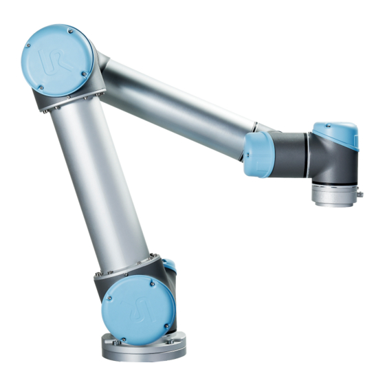
Preface Congratulations on the purchase of your new Universal Robot, UR5. The robot can be programmed to move a tool, and communicate with other ma- chines using electrical signals. It is an arm composed of extruded aluminum tubes and joints. Using our patented programming interface, PolyScope, it is easy to pro- gram the robot to move the tool along a desired trajectory. -
Page 12: Important Safety Notice
It is also helpful, though not necessary, to be familiar with elementary concepts of programming. No special knowledge about robots in general or Universal Robots in particular is required. Where to Find More Information The support website (http://www.universal-robots.com/support), avail- able to all UR distributors, contains additional information, such as: •... -
Page 13: I Hardware Installation Manual
Part I Hardware Installation Manual... -
Page 15: Safety
• Marking the robot installation with relevant signs and contact information of the integrator; • Collecting all documentation in a technical file; including the risk assessment and this manual. Guidance on how to find and read applicable standards and laws is provided on http://universal-robots.com/support/ Version 3.4.5 UR5/CB3... -
Page 16: Limitation Of Liability
WARNING: This indicates a potentially hazardous hot surface which, if touched, could result in injury. CAUTION: This indicates a situation which, if not avoided, could result in damage to the equipment. UR5/CB3 Version 3.4.5... -
Page 17: General Warnings And Cautions
10. Be aware of robot movement when using the teach pendant. 11. Do not enter the safety range of the robot or touch the robot when the system is in operation. Version 3.4.5 UR5/CB3... - Page 18 It is recommended to test the robot program using tem- porary waypoints outside the workspace of other machines. Universal Robots cannot be held responsible for any damages caused to the robot or to other equipment due to program- ming errors or malfunctioning of the robot.
-
Page 19: Intended Use
first time. A part of the risk assessment conducted by the integrator is to identify the proper safety configuration settings, as well as the need for additional emer- gency stop buttons and/or other protective measures required for the specific robot application. Version 3.4.5 UR5/CB3... - Page 20 (e.g. an enabling device to protect the integra- tor during set-up and programming). Universal Robots has identified the potential significant hazards listed below as hazards which must be considered by the integrator. Note that other significant hazards might be present in a specific robot installation.
-
Page 21: Emergency Stop
1. Moving the robot arm manually is intended for urgent emer- gencies only and might damage the joints. 2. If the brake is released manually, gravitational pull can cause the robot arm to fall. Always support the robot arm, tool and work item when releasing the brake. Version 3.4.5 UR5/CB3... - Page 22 1.9 Movement Without Drive Power UR5/CB3 I-10 Version 3.4.5...
-
Page 23: Safety-Related Functions And Interfaces
The robot has a number of safety-related functions that can be used to limit the movement of its joints and of the robot Tool Center Point (TCP). The TCP is the center point of the output flange with the addition of the TCP offset. The limiting safety-related functions are: Version 3.4.5 I-11 UR5/CB3... -
Page 24: Stopping Times Of The Safety System
Violations of limits will hence only occur in exceptional cases. Nevertheless, if a limit is violated, the safety system issues a Stop Category 0. Stop Categories are according to IEC 60204-1, see Glossary for more details. UR5/CB3 I-12 Version 3.4.5... -
Page 25: Safety Modes
Normal and Reduced. Safety limits can be configured for each of these two modes. Reduced mode is active when the robot TCP is positioned beyond a Trigger Reduced mode plane or when triggered by a safety input. Version 3.4.5 I-13 UR5/CB3... - Page 26 The safety system issues a Stop Category 0 if a violation of these limits appears. WARNING: Notice that limits for the joint position, the TCP position, and the TCP orientation are disabled in Recovery Mode. Take caution when moving the robot arm back within the limits. UR5/CB3 I-14 Version 3.4.5...
-
Page 27: Safety-Related Electrical Interfaces
0.05 rad from the position it had when the speed was measured below 0.2 Additionally, for a Stop Category 1, the safety system monitors that after the robot arm is at rest, the powering off is finalized within 600 ms. Furthermore, after a Version 3.4.5 I-15 UR5/CB3... -
Page 28: Safety-Related Electrical Outputs
1000 ms 1250 ms System Emergency Stop 250 ms 1000 ms 1250 ms Safeguard Stop 250 ms 1000 ms 1250 ms 2.5.2 Safety-related Electrical Outputs The table below gives an overview of the safety-related electrical outputs: UR5/CB3 I-16 Version 3.4.5... - Page 29 If a safety output is not set properly, the safety system issues a Stop Category 0, with the following worst-case reaction times: Safety Output Worst Case Reaction Time System emergency stop 1100 ms Robot moving 1100 ms Robot not stopping 1100 ms Reduced mode 1100 ms Not reduced mode 1100 ms Version 3.4.5 I-17 UR5/CB3...
- Page 30 2.5 Safety-related Electrical Interfaces UR5/CB3 I-18 Version 3.4.5...
-
Page 31: Transportation
Use proper lifting equipment. All regional and national guidelines for lifting shall be followed. Universal Robots cannot be held responsible for any damage caused by transportation of the equipment. 2. Make sure to mount the robot according to the mounting in- structions in chapter 4. - Page 32 UR5/CB3 I-20 Version 3.4.5...
-
Page 33: Mechanical Interface
Electrical installation instructions in chapter 5 must be observed. 4.2 Workspace of the Robot The workspace of the UR5 robot extends 850 mm from the base joint. It is important to consider the cylindrical volume directly above and directly below the robot base when a mounting place for the robot is chosen. -
Page 34: Mounting
A wet control box could cause death. 2. The control box and teach pendant must not be exposed to dusty or wet environments that exceed IP20 rating. Pay spe- cial attention to environments with conductive dust. UR5/CB3 I-22 Version 3.4.5... - Page 35 Surface on which the robot is fitted. It should be flat within 0.05mm Outer diameter of robot mounting flange Cable exit 132 ±0,5 Figure 4.1: Holes for mounting the robot. Use four M8 bolts. All measurements are in mm. Version 3.4.5 I-23 UR5/CB3...
- Page 36 4.3 Mounting Figure 4.2: The tool output flange, ISO 9409-1-50-4-M6. This is where the tool is mounted at the tip of the robot. All measures are in mm. UR5/CB3 I-24 Version 3.4.5...
-
Page 37: Maximum Payload
figure 4.3. The center of gravity offset is defined as the distance between the center of the tool output flange and the center of gravity. Payload [kg] Center of gravity offset [mm] Figure 4.3: Relationship between the maximum allowed payload and the center of gravity offset. Version 3.4.5 I-25 UR5/CB3... - Page 38 4.4 Maximum Payload UR5/CB3 I-26 Version 3.4.5...
-
Page 39: Electrical Interface
3. Some I/O inside the control box can be configured for either normal or safety-related I/O. Read and understand the com- plete section 5.3. Version 3.4.5 I-27 UR5/CB3... - Page 40 EMC problems are found to happen usu- ally in welding processes and are normally prompted by error messages in the log. Universal Robots cannot be held respon- sible for any damages caused by EMC problems. 2. I/O cables going from the control box to other machinery and factory equipment may not be longer than 30m, unless ex- tended tests are performed.
- Page 41 24V supply. The lower two terminals (24V and 0V) in the block are the 24V input to supply the I/O. The default configuration is to use the internal power supply, see below. Power Version 3.4.5 I-29 UR5/CB3...
- Page 42 Note: *For resistive loads or inductive loads of maximum 1H. NOTE: The word “configurable” is used for I/O that can be configured as either safety-related I/O or normal I/O. These are the yellow terminals with black text. UR5/CB3 I-30 Version 3.4.5...
-
Page 43: Safety I/O
Configuring a set of configurable I/O for safety functions are done through the GUI, see part II. Some examples of how to use safety I/O are shown in the following subsections. Version 3.4.5 I-31 UR5/CB3... - Page 44 It is often desired to set up a common emergency stop circuit when the robot is used together with other machines. By doing so, the operator does not need to think about which emergency stop buttons to use. UR5/CB3 I-32 Version 3.4.5...
- Page 45 The configurable I/O can be used to setup a reset button outside the door, to reactivate robot motion. Another example where automatic resume can be appropriate is when using a safety mat or a safety-related laser scanner, see below. Version 3.4.5 I-33 UR5/CB3...
-
Page 46: General Purpose Digital I/O
PLC systems. All digital outputs can be disabled automatically when program execution is stopped, see more in part II. In this mode, the output is always low when a program is not running. Examples are UR5/CB3 I-34 Version 3.4.5... -
Page 47: General Purpose Analog I/O
The analog I/O interface is the green terminal. It can be used to set or measure voltage (0-10V) or current (4-20mA) from and to other equipment. The following is recommended to achieve the highest accuracy. • Use the AG terminal closest to the I/O. The pair share a common mode filter. Version 3.4.5 I-35 UR5/CB3... - Page 48 [AOx - AG] The following examples show how to use the analog I/O. 5.3.6.1 Using an analog output Below is an example of how to control a conveyor belt with an analog speed control input. Analog Power UR5/CB3 I-36 Version 3.4.5...
-
Page 49: Remote On/Off Control
Input current [ON / OFF] Activation time [ON] The following examples show how to use remote ON/OFF. NOTE: A special feature in the software can be used to load and start pro- grams automatically, see part II. Version 3.4.5 I-37 UR5/CB3... -
Page 50: Tool I/O
Signal 0V (GND) Gray 0V/+12V/+24V (POWER) Blue Tool output 0 (TO0) Pink Tool output 1 (TO1) Yellow Tool input 0 (TI0) Green Tool input 1 (TI1) White Analog input 2 (AI2) Brown Analog input 3 (AI3) UR5/CB3 I-38 Version 3.4.5... -
Page 51: Tool Digital Outputs
An example of how to use a digital output is shown in the following subsection. CAUTION: 1. The digital outputs in the tool are not current limited and overriding the specified data can cause permanent damage. Version 3.4.5 I-39 UR5/CB3... -
Page 52: Tool Digital Inputs
Logical high voltage Input resistance An example of how to use a digital input is shown in the following subsection. 5.4.2.1 Using the Tool Digital Inputs The example below shows how to connect a simple button. POWER UR5/CB3 I-40 Version 3.4.5... -
Page 53: Tool Analog Inputs
5.4.3.2 Using the Tool Analog Inputs, Differential The example below shows how to connect an analog sensor with a differential out- put. Connect the negative output part to GND (0V) and it works in the same way as a non-differential sensor. POWER Version 3.4.5 I-41 UR5/CB3... -
Page 54: Ethernet
It is recommended to install a main switch to power off all equipment in the robot application as an easy means for lockout and tagout under service. The electrical specifications are shown in the table below. UR5/CB3 I-42 Version 3.4.5... -
Page 55: Robot Connection
The cable from the robot must be plugged into the connector at the bottom of the control box, see illustration below. Ensure that the connector is properly locked before turning on the robot arm. Disconnecting the robot cable may only be done when the robot power is turned off. Version 3.4.5 I-43 UR5/CB3... - Page 56 5.7 Robot connection CAUTION: 1. Do not disconnect the robot cable when the robot arm is turned on. 2. Do not extend or modify the original cable. UR5/CB3 I-44 Version 3.4.5...
-
Page 57: Maintenance And Repair
Repairs shall only be performed by authorized system integrators or by Universal Robots. All parts returned to Universal Robots shall be returned according to the service manual. 6.1 Safety Instructions After maintenance and repair work, checks must be carried out to ensure the re- quired safety level. -
Page 58: Safety Instructions
High voltages (up to 600 V) can be present inside these power supplies for several hours after the control box has been switched off. 5. Prevent water and dust from entering the robot arm or control box. UR5/CB3 I-46 Version 3.4.5... -
Page 59: Disposal And Environment
Fee for disposal and handling of electronic waste of UR robots sold on the Danish market is prepaid to DPA-system by Universal Robots A/S. Importers in countries covered by the European WEEE Directive 2012/19/EU must make their own regis- tration to the national WEEE register of their country. - Page 60 UR5/CB3 I-48 Version 3.4.5...
-
Page 61: Certifications
2006/42/EC. Note that a CE mark is not affixed according to this directive for partly completed machinery. If the UR robot is used in a pesticide application, then note the presence of directive 2009/127/EC. The declaration of incorporation according to 2006/42/EC annex II 1.B. is shown in appendix B. Version 3.4.5 I-49 UR5/CB3... -
Page 62: Declarations According To Eu Directives
B. A CE mark is affixed according to CE marking directives above. Regarding waste of electric and electronic equipment see chapter 7. For information about standards applied during the development of the robot, see appendix C. UR5/CB3 I-50 Version 3.4.5... -
Page 63: Warranties
In case of a device exhibiting defects, Universal Robots shall not be liable for any indirect, incidental, special or consequential damages, including but not limited to, lost profits, loss of use, loss of production or damage to other... -
Page 64: Disclaimer
9.2 Disclaimer UR5/CB3 I-52 Version 3.4.5... -
Page 65: A Stopping Time And Stopping Distance
Stopping Distance (rad) Stopping time (ms) Joint 0 (BASE) 0.31 Joint 1 (SHOULDER) 0.70 Joint 2 (ELBOW) 0.22 According to IEC 60204-1, see Glossary for more details. Version 3.4.5 I-53 UR5/CB3... -
Page 66: Stop Category 0 Stopping Distances And Times
A.1 Stop Category 0 stopping distances and times UR5/CB3 I-54 Version 3.4.5... -
Page 67: B Declarations And Certificates
Denmark hereby declares that the product described below Industrial robot UR5/CB3 may not be put into service before the machinery in which it will be incorporated is declared in confor- mity with the provisions of Directive 2006/42/EC, as amended by Directive 2009/127/EC, and with the regulations transposing it into national law. -
Page 68: Safety System Certificate
B.2 Safety System Certificate B.2 Safety System Certificate UR5/CB3 I-56 Version 3.4.5... -
Page 69: Environmental Test Certificate
Conclusion The two robot arms UR5 and UR10 including their control box and teach pendant have been tested according to the below listed standards. The test results are given in the DELTA report listed above. The tests were carried out as specified and the test criteria for environmental tests as specified in Annex 1 of the report were fulfilled. -
Page 70: Emc Test Certificate
Universal Robots A/S Technical report(s) DELTA Project T207371, EMC Test of UR5 and UR10 - DANAK-19/13884, dated 26 March 2014 DELTA Project T209172, EMC Test of UR3 - DANAK-19/14667, dated 05 November 2014 UR EMC Test Specification G3 rev 3, dated 30 October 2014... -
Page 71: B.5 Cleanroom Test Certificates
TÜV SÜD Industrie Service GmbH hereby confirms UNIVERSAL ROBOTS A/S situated at Energivej 25, 5260 Odense S; Dänemark, that the product Roboter, Model: UR5 / Typ INDUSTRIAL the cleanroom compatibility of the equipment for the ISO Class 5 according ISO 14644-1. -
Page 72: Cleanroom Test Certificates
The implementation of the testing and certification is carried out by TÜV SÜD Industrie Service GmbH. Certificate Nr.: 2589737-04 Report-Nr.: 203195 Valid till: August 2018 Dipl.-Ing. (FH) Walter Ritz Berlin, 25. August 2016 TÜV SÜD Industrie Service GmbH Wittestraße 30, Haus L, 13509 Berlin UR5/CB3 I-60 Version 3.4.5... -
Page 73: C Applied Standards
EN ISO 13850:2008 (E) [Stop Category 1 - 2006/42/EC] EN ISO 13850:2015 [Stop Category 1 - 2006/42/EC] Safety of machinery – Emergency stop – Principles for design The emergency stop function is designed as a Stop Category 1 according to this standard. Stop Category Version 3.4.5 I-61 UR5/CB3... - Page 74 Additionally see clarification in ISO/TS 15066 clause 5.4.5. • “5.10 Collaborative operation requirements”. The power and force limiting collaborative safety According to ISO 13849-1, see Glossary for more details. UR5/CB3 I-62 Version 3.4.5...
- Page 75 The language is changed from British English to American English, but the content is the same. Note that part two (ISO 10218-2) of this standard is intended for the integrator of the robot system, and not Universal Robots. CAN/CSA-Z434-14 Industrial Robots and Robot Systems – General Safety Requirements This Canadian standard is the ISO standards ISO 10218-1 (see above) and -2 combined into one docu- ment.
- Page 76 IEC 60947-5-5/A1:2005 EN 60947-5-5/A11:2013 [2006/42/EC] Low-voltage switchgear and controlgear Part 5-5: Control circuit devices and switching elements - Electrical emergency stop device with mechanical latching function UR5/CB3 I-64 Version 3.4.5...
- Page 77 Protection against electric shock – Common aspects for installation and equipment UR robots are constructed in compliance with this standard to provide protection against electrical shock. A protective earth/ground connection is mandatory, as defined in the Hardware Installation Manual. Version 3.4.5 I-65 UR5/CB3...
- Page 78 Part 1: Principles, requirements and tests Part 5: Comprehensive method for determining clearances and creepage distances equal to or less than 2 mm The electrical circuitry of UR robots is designed in compliance with this standard. UR5/CB3 I-66 Version 3.4.5...
- Page 79 EUROMAP 67:2015, V1.11 Electrical Interface between Injection Molding Machine and Handling Device / Robot UR robots equipped with the E67 accessory module to interface injection molding machines comply with this standard. Version 3.4.5 I-67 UR5/CB3...
- Page 80 UR5/CB3 I-68 Version 3.4.5...
-
Page 81: D Technical Specifications
The robot can work in an ambient temperature range of 0-50 C Power supply 100-240 VAC, 50-60 Hz Calculated operating life 35,000 hours Cabling Cable between robot and control box (6 m / 236 in) Cable between touchscreen and control box (4.5 m / 177 in) Version 3.4.5 I-69 UR5/CB3... - Page 82 UR5/CB3 I-70 Version 3.4.5...
-
Page 83: Polyscope Manual
Part II PolyScope Manual... -
Page 85: Safety Configuration
10 Safety Configuration 10.1 Introduction The robot is equipped with an advanced safety system. Depending on the partic- ular characteristics of the robot workspace, the settings for the safety system must be configured to guarantee the safety of all personnel and equipment around the robot. -
Page 86: Changing The Safety Configuration
10.2 Changing the Safety Configuration The safety settings consist of a number of limit values used to constrain the move- ments of the robot arm, and of safety function settings for the configurable inputs and outputs. They are defined in the following subtabs of the safety screen: •... -
Page 87: Safety Synchronization And Errors
10.3 Safety Synchronization and Errors The recommended procedure for changing the safety configuration is as follows: 1. Make sure that the changes are in compliance with the risk assessment con- ducted by the integrator. 2. Adjust safety settings to the appropriate level defined by the risk assessment conducted by the integrator. -
Page 88: Tolerances
10.6 Safety Modes 2. Revert back to the previously applied safety configuration. This will disregard all changes and allow you to continue to the desired selected destination. 10.4 Tolerances The Robot Arm uses built-in tolerances that prevent safety violations. A safety tol- erance is the difference between a safety limit and a maximum operational value. -
Page 89: Freedrive Mode
10.7 Freedrive Mode limits: Normal mode: The safety mode that is active by default; Reduced mode: Active when the robot TCP is positioned beyond a Trigger Reduced mode plane (see 10.12), or when triggered using a configurable input (see 10.13). Recovery mode: When the robot arm is in violation of one of the other modes (i.e. -
Page 90: Password Lock
10.9 Apply feature can be used to forcefully move specific joints to a desired position without releasing all brakes in the robot arm. To enable Backdrive: 1. Press ON to enable power for the joints. The robot state is set to “Idle”. Do not release the brakes (i.e. -
Page 91: General Limits
10.10 General Limits Furthermore, on confirmation the changes are automatically saved as part of the current robot installation. See 13.5 for further information on saving the robot in- stallation. 10.10 General Limits The general safety limits serve to limit the linear speed of the robot TCP as well as the force it may exert on the environment. - Page 92 10.10 General Limits the closer the speed comes to the limit. The force is generated when the current speed is within approximately 250 of the limit. Basic Settings The initial general limits subpanel, shown as the default screen, features a slider with four predefined sets of values for force, power, speed, and momentum limits in both Normal and Reduced mode.
-
Page 93: Joint Limits
10.11 Joint Limits (see 10.4). Note that the minus sign displayed with the tolerance value is only there to indicate that the tolerance is subtracted from the actual entered value. The safety system performs a Stop Category 0, should the robot arm exceed the limit (without tolerance). -
Page 94: Boundaries
10.12 Boundaries Maximum Speed This option defines the maximum angular velocity for each joint. This is done by tapping the corresponding text field and entering the new value. The highest accepted value is listed in the column titled Maximum. None of the values can be set below the tolerance value. -
Page 95: Selecting A Boundary To Configure
10.12 Boundaries WARNING: Defining safety planes only limits the TCP and not the overall limit for the robot arm. This means that although a safety plane is spec- ified, it does not guarantee that other parts of the robot arm will obey this restriction. -
Page 96: D Visualization
10.12 Boundaries 10.12.2 3D visualization The 3D View displays the configured safety planes and the orientation boundary limit for the robot tool together with the current position of the robot arm. All configured boundary entries where the visibility toggle is selected (i.e. showing icon) in the Safety Boundaries section are displayed together with the current selected boundary limit. - Page 97 10.12 Boundaries Name The Name text field allows the user to assign a name to the selected safety plane. Change the name by tapping the text field and entering a new name. Copy Feature The position and normal of the safety plane is specified using a feature (see 13.12) from the current robot installation.
- Page 98 10.12 Boundaries shown. Displacement When a feature has been selected in the drop down box in the lower left portion of the Safety Plane Properties panel, the safety plane can be translated by tapping the Displacement text field in the lower right portion of this panel and entering a value.
-
Page 99: Tool Boundary Configuration
10.12 Boundaries applied for each limit value. Once the robot TCP is positioned 20 mm or further from the Trigger Reduced mode plane (on the Normal mode side), the Reduced mode limit set is no longer active and the Normal mode limit set is enforced. If the predicted trajectory takes the robot TCP through a Trigger Reduced mode plane, the robot arm will start decelerating even before passing through the plane if it is about to exceed joint speed, tool speed or momentum limit in the new limit set. - Page 100 10.12 Boundaries Choosing the <Undefined> item clears the configuration of the plane. It should be noted that when the limit has been configured by selecting a feature, the orientation information is only copied to the limit; the limit is not linked to that feature.
-
Page 101: Safety I/O
10.13 Safety I/O 10.13 Safety I/O This screen defines the Safety functions for configurable inputs and outputs (I/Os). The I/Os are divided between the inputs and outputs, and are paired up so that each function is providing a Category 3 and PLd I/O. Each Safety function can only control one pair of I/Os. - Page 102 10.13 Safety I/O that safety planes can also cause a transition to Reduced mode (see 10.12.3 for more details). Safeguard Reset If Safeguard Stop is wired in the safety I/Os, then this input is used to ensure the Safeguard Stopped state continues until a reset is trig- gered.
-
Page 103: Output Signals
10.13 Safety I/O NOTE: After the Safety I/O configuration with 3-Position Switch en- abled is confirmed, the Welcome screen is automatically shown. The Welcome screen is also automatically displayed when the op- erational mode changes from Programming to Running. 10.13.2 Output Signals For the output signals the following Safety functions can be applied. - Page 104 10.13 Safety I/O II-22 Version 3.4.5...
-
Page 105: Begin Programming
11 Begin programming 11.1 Introduction The Universal Robot arm is composed of tubes and joints. The joints with their usual names are shown in Figure 11.1. The Base is where the robot is mounted, and at the other end (Wrist 3) the tool of the robot is attached. By coordinating the motion of each of the joints, the robot can move its tool around freely, with the exception of the area directly above and directly below the base. -
Page 106: Installing The Robot Arm And Control Box
11.2 Getting Started 11.2.1 Installing the Robot Arm and Control Box To install the robot arm and control box, do the following: 1. Unpack the robot arm and the control box. 2. Mount the robot arm on a sturdy and vibration-free surface. 3. -
Page 107: Quick Start
11.2 Getting Started 11.2.4 Quick Start To quickly start up the robot after it has been installed, perform the following steps: 1. Press the emergency stop button on the front side of the teach pendant. 2. Press the power button on the teach pendant. 3. -
Page 108: Polyscope Programming Interface
11.3 PolyScope Programming Interface 1. Touch the Program Robot button and select Empty Program. 2. Touch the Next button (bottom right) so that the <empty> line is selected in the tree structure on the left side of the screen. 3. Go to the Structure tab. 4. - Page 109 11.3 PolyScope Programming Interface The picture above shows the Welcome Screen. The bluish areas of the screen are buttons that can be pressed by pressing a finger or the backside of a pen against the screen. PolyScope has a hierarchical structure of screens. In the programming environment, the screens are arranged in tabs, for easy access on the screens.
-
Page 110: Welcome Screen
11.4 Welcome Screen 11.4 Welcome Screen After booting up the controller PC, the welcome screen is shown. The screen offers the following options: • Run Program: Choose and run an existing program. This is the simplest way to operate the robot arm and control box. •... -
Page 111: Initialization Screen
11.5 Initialization Screen 11.5 Initialization Screen On this screen you control the initialization of the robot arm. Robot arm state indicator The status LED gives an indicaton of the robot arm’s running state: • A bright red LED indicates that the robot arm is currently in a stopped state where the reasons can be several. - Page 112 11.5 Initialization Screen Before starting up the robot arm, it is very important to verify that both the active payload and the active installation correspond to the actual situation the robot arm is currently in. Initializing the robot arm DANGER: Always verify that the actual payload and installation are correct before starting up the robot arm.
-
Page 113: On-Screen Editors
12 On-screen Editors 12.1 On-screen Expression Editor While the expression itself is edited as text, the expression editor has a number of buttons and functions for inserting the special expression symbols, such as multiplication and for less than or equal to. The keyboard symbol button in the top left of the screen switches to text-editing of the expression. - Page 114 12.2 Pose Editor Screen Robot The current position of the robot arm and the specified new target position are shown in 3D graphics. The 3D drawing of the robot arm shows the current position of the robot arm, and the “shadow” of the robot arm shows the target position of the robot arm controlled by the specified values on the right hand side of the screen.
- Page 115 12.2 Pose Editor Screen The text boxes show the full coordinate values of that TCP relative to the selected feature. X, Y and Z control the position of the tool, while RX, RY and RZ control the orientation of the tool. Use the drop down menu above the RX, RY and RZ boxes to choose the orientation representation.
- Page 116 12.2 Pose Editor Screen II-34 Version 3.4.5...
-
Page 117: Robot Control
13 Robot Control 13.1 Move Tab On this screen you can always move (jog) the robot arm directly, either by translat- ing/rotating the robot tool, or by moving robot joints individually. 13.1.1 Robot The current position of the robot arm is shown in 3D graphics. Push the magnifying glass icons to zoom in/out or drag a finger across to change the view. -
Page 118: Feature And Tool Position
13.1 Move Tab When the robot TCP no longer is in the proximity of the limit, the 3D representation disappears. If the TCP is in violation or very close to violating a boundary limit, the visualization of the limit turns red. 13.1.2 Feature and Tool Position In the top right corner of the screen, the feature selector can be found. -
Page 119: I/O Tab
13.2 I/O Tab WARNING: 1. Make sure to use the correct installation settings (e.g. Robot mounting angle, weight in TCP, TCP offset). Save and load the installation files along with the program. 2. Make sure that the TCP settings and the robot mounting set- tings are set correctly before operating the Freedrive but- ton. -
Page 120: Modbus Client I/O
13.4 AutoMove Tab name. Configurable outputs that are reserved for safety settings are not togglable and will be displaed as LED’s only. The electrical details of the signals are described in chapter 5.3. Analog Domain Settings The analog I/O’s can be set to either current [4-20mA] or voltage [0-10V] output. - Page 121 13.4 AutoMove Tab Animation The animation shows the movement the robot arm is about to perform. CAUTION: Compare the animation with the position of the real robot arm and make sure that the robot arm can safely perform the movement without hitting any obstacles.
-
Page 122: Installation Load/Save
13.5 Installation Load/Save 13.5 Installation Load/Save The Robot Installation covers all aspects of how the robot arm and control box are placed in the working environment. It includes the mechanical mounting of the robot arm, electrical connections to other equipment, as well as all options on which the robot program depends. -
Page 123: Installation Tcp Configuration
13.6 Installation TCP Configuration 13.6 Installation TCP Configuration A Tool Center Point (TCP) is a characteristic point on the robot’s tool. Several named TCPs can be defined on this screen. Each TCP contains a translation and a rotation relative to the center of the tool output flange, as indicated on the on-screen graph- ics. -
Page 124: Teaching Tcp Position
13.6 Installation TCP Configuration a program, the default TCP is set as the active one. Within a program, any of the specified TCPs can be set as the active one for a particular movement of the robot (see 14.5 and 14.10). 13.6.3 Teaching TCP position TCP position coordinates can be calculated automatically as follows: 1. -
Page 125: Teaching Tcp Orientation
13.6 Installation TCP Configuration 13.6.4 Teaching TCP orientation TCP orientation can be calculated automatically as follows: 1. Tap the Orientation button. 2. Select a feature from the drop-down list. For additional information about how new features can be defined, see 13.12. 3. -
Page 126: Installation Mounting
13.7 Installation Mounting WARNING: Make sure to use the correct installation settings. Save and load the installation files along with the program. 13.7 Installation Mounting Here the mounting of the robot arm can be specified. This serves two purposes: 1. Making the robot arm look right on the screen. 2. -
Page 127: Installation I/O Setup
13.8 Installation I/O Setup arm’s mounting. The three top right side buttons set the angle to ceiling (180 ), wall (90 ), floor (0 ). The Tilt buttons can be used to set an arbitrary angle. The buttons on the lower part of the screen are used to rotate the mounting of the robot arm to match the actual mounting. -
Page 128: I/O Signal Type
13.9 Installation Safety 13.8.1 I/O Signal Type To limit the number of signals listed in the Input and Output sections, use the View drop-down menu at the top of the screen to change the displayed content based on signal type. 13.8.2 Assigning User-defined Names It is possible to associate names to input and output signals. -
Page 129: Installation Variables
13.10 Installation Variables 13.10 Installation Variables Variables created here are called installation variables and can be used just like normal program variables. Installation variables are special because they keep their value even if a program is stopped and then started again, and when the robot arm and/or control box is powered down and powered up again. -
Page 130: Installation Modbus Client I/O Setup
13.11 Installation MODBUS client I/O Setup options to resolve the issue: either use the installation variables of the same name instead of the program variable or have the conflicting variables renamed automat- ically. 13.11 Installation MODBUS client I/O Setup Here, the MODBUS client (master) signals can be set up. Connections to MOD- BUS servers (or slaves) on specified IP addresses can be created with input/output signals (registers or digital). - Page 131 13.11 Installation MODBUS client I/O Setup Sequential mode Available only when Show Advanced Options (see 13.11) is selected. Selecting this check- box forces the modbus client to wait for a response before sending the next request. This mode is required by some fieldbus units. Turning this option on may help when there are multiple signals, and increasing request frequency results in signal disconnects.
- Page 132 13.11 Installation MODBUS client I/O Setup Set signal name Using the on-screen keyboard, the user can give the signal a name. This name is used when the signal is used in programs. Signal value Here, the current value of the signal is shown. For register signals, the value is expressed as an unsigned integer.
-
Page 133: Installation Features
13.12 Installation Features • Slave Address: This text field can be used to set a specific slave address for the requests corresponding to a specific signal. The value must be in the range 0-255 both included, and the default is 255. If you change this value, it is recommended to consult the manual of the remote MODBUS device to verify its functionality when changing slave address. -
Page 134: Using A Feature
13.12 Installation Features vision systems, blanks or boundaries which typically exist in the surroundings of the robot arm. The Feature as a concept, is basically a representation of such an object that has been defined with a name for future reference and a six dimensional pose (position and orientation) relative to the robot base. - Page 135 13.12 Installation Features the feature (see section 14.5). This allows for easy adaptation of a robot program, e.g. when having multiple robot stations or when an object is dynamically moved during program runtime or permanently moved in the scene. By simply adjusting the referenced feature of a particular object, all movements of the program that should be relative to the object is moved accordingly.
-
Page 136: New Point
13.12 Installation Features Move robot here Pressing this button will move the robot arm towards the selected feature. At the end of this movement, the coordinate systems of the feature and the TCP will coin- cide. 13.12.2 New Point Push this button to add a point feature to the installation. The point feature is typically chosen when defining a safety boundary or a global home configuration of the robot arm. -
Page 137: New Plane
13.12 Installation Features Figure 13.3: Definition of the line feature 13.12.4 New Plane Push this button to add a plane feature to the installation. The plane feature is typically chosen when there is a need for a frame with high precision, e.g. when working with a vision system or doing movements relative to a table. -
Page 138: Example: Manually Updating A Feature To Adjust A Program
13.12 Installation Features 13.12.5 Example: Manually updating a feature to adjust a program Consider an application where multiple parts of a robot program is relative to a table. In figure 13.4 this is illustrated as the movement from waypoints wp1 through wp4. -
Page 139: Example: Dynamically Updating A Feature Pose
13.12 Installation Features sure that it is selected as Variable, the program with a MoveL command configured relative to the plane can be easily applied on additional robots by just updating the installation with the actual position of the table. The concept applies to any number of Features in an application, to achieve a flexi- ble program that can solve the same task on many robots even though e.g. -
Page 140: Conveyor Tracking Setup
13.13 Conveyor Tracking Setup Robot Program MoveJ if (digital_input[0]) then P1_var = P1 else P1_var = P2 MoveL # Feature: P1_var Figure 13.7: Switching from one plane feature to another 13.13 Conveyor Tracking Setup When using a conveyor, the robot can be configured to track it’s movement. The Conveyor Tracking Setup provides options for configuring the robot to work with absolute and incremental encoders, as well as, linear and circular conveyors. -
Page 141: Installation Default Program
13.14 Installation Default Program Circular conveyors When tracking a circular conveyor, the center point of the conveyor (circle) must be defined. The value of Ticks per revolution must be the number of ticks the encoder generates when the conveyor rotates one full revolution. 13.14 Installation Default Program This screen contains settings for automatically loading and starting a default pro-... -
Page 142: Starting A Default Program
13.15 Log Tab 13.14.2 Starting a Default Program The default program can be auto started in the Run Program screen. When the default program is loaded and the specified external input signal edge transition is detected, the program will be started automatically. Note, on startup the current input signal level is undefined and chosing a transition that matches the signal level on startup will start the program immediately. -
Page 143: Load Screen
13.16 Load Screen Robot Health The top half of the screen displays the health of the robot arm and control box. The left part shows information related to the control box of the robot, while the right part shows information about each robot joint. Each robot joint shows information for temperaure of the motor and electronics, the load of the joint and the voltage at the joint. - Page 144 13.16 Load Screen Screen layout This image shows the actual load screen. It consists of the following important areas and buttons: Path history The path history shows a list of the paths leading up to the present location. This means that all parent directories up to the root of the computer are shown.
-
Page 145: Run Tab
13.17 Run Tab of the field. This will cause an on-screen keyboard to pop up where the user can enter the file name directly on the screen. Open button Clicking on the Open button, will open the currently selected file and return to the previous screen. - Page 146 13.17 Run Tab Furthermore, in this tab a default program can be automatically loaded and started based on an external input signal edge transition (see 13.14). The combination of auto loading and starting of a default program and auto initialization on power up can, for instance, be used to integrate the robot arm into other machinery.
-
Page 147: Programming
14 Programming 14.1 New Program A new robot program can start from either a template or from an existing (saved) robot program. A template can provide the overall program structure, so only the details of the program need to be filled in. Version 3.4.5 II-65... -
Page 148: Program Tab
14.2 Program Tab 14.2 Program Tab The program tab shows the current program being edited. 14.2.1 Program Tree The program tree on the left side of the screen displays the program as a list of com- mands, while the area on the right side of the screen displays information relating to the current command. -
Page 149: Program Execution Indication
14.2 Program Tab 14.2.2 Program Execution Indication The program tree contains visual cues informing about the command currently be- ing executed by the robot controller. A small indicator icon is displayed to the left of the command icon, and the name of the executing command and any commands of which this command is a sub-command (typically identified by the com- mand icons) are highlighted with blue. -
Page 150: Undo/Redo Buttons
14.2 Program Tab 14.2.4 Undo/Redo Buttons The buttons with icons below the program tree serve to undo and redo changes made in the program tree and in the commands it contains. 14.2.5 Program Dashboard The lowest part of the screen is the Dashboard. The Dashboard features a set of but- tons similar to an old-fashioned tape recorder, from which programs can be started and stopped, single-stepped and restarted. -
Page 151: Variables
14.3 Variables 14.3 Variables A robot program can make use of variables to store and update various values during runtime. Two kinds of variables are available: Installation variables: These can be used by multiple programs and their names and values are persisted together with the robot installation (see 13.10 for further details). -
Page 152: Command: Move
14.5 Command: Move 14.5 Command: Move The Move command controls the robot motion through the underlying waypoints. Waypoints have to be under a Move command. The Move command defines the acceleration and the speed at which the robot arm will move between those way- points. - Page 153 14.5 Command: Move determined by the actual value of the variable feature when the robot program runs. • moveP will move the tool linearly with constant speed with circular blends, and is intended for some process operations, like gluing or dispensing. The size of the blend radius is by default a shared value between all the way- points.
- Page 154 14.5 Command: Move Cruise Deceleration Acceleration Time Figure 14.1: Speed profile for a motion. The curve is divided into three segments: acceleration, cruise and deceleration. The level of the cruise phase is given by the speed setting of the motion, while the steepness of the acceleration and deceleration phases is given by the acceleration parameter.
-
Page 155: Command: Fixed Waypoint
14.6 Command: Fixed Waypoint 14.6 Command: Fixed Waypoint A point on the robot path. Waypoints are the most central part of a robot program, telling the robot arm where to be. A fixed position waypoint is given by physically moving the robot arm to the position. Setting the waypoint Press this button to enter the Move screen where you can specify the robot arm’s position for this waypoint. - Page 156 14.6 Command: Fixed Waypoint at Waypoint 3 (WP_3). To avoid collisions with the object and other obstacles (O), the robot must approach WP_3 in the direction coming from Waypoint 2 (WP_2). So three waypoints are introduced to create a path that fulfils the requirements. WP_2 WP_1 WP_3...
- Page 157 14.6 Command: Fixed Waypoint WP_1 WP_2 WP_3 Figure 14.3: Blend over WP_2 with radius r, initial blend position at p1 and final blend position at p2. O is an obstacle. WP_1 WP_2 WP_3 WP_4 Figure 14.4: Blend radius overlap not allowed (*). That is, in the program in figure 14.5 the blend around WP_1 is affected by WP_2.
- Page 158 14.6 Command: Fixed Waypoint WP_I MoveL WP_1 WP_I WP_1 (blend) WP_2 (blend) if (digital_input[1]) then WP_2 WP_F_1 else WP_F_2 WP_F_1 WP_F_2 Figure 14.5: WP_I is the initial waypoint and there are two potential final waypoints WP_F_1 and WP_F_2, depending on a conditional expression. The conditional if expression is evaluated when the robot arm enters the second blend (*).
- Page 159 14.6 Command: Fixed Waypoint Of the different combinations, bullets 2, 3 and 4 will result in trajectories that keep within the boundaries of the original trajectory in Cartesian space. An example of a blend between different trajectory types (bullet 2) can be seen in figure 14.7. WP_2 WP_1 WP_3...
-
Page 160: Command: Relative Waypoint
14.7 Command: Relative Waypoint 14.7 Command: Relative Waypoint A waypoint with the position given relative to the robot arm’s previous position, such as “two centimeters to the left”. The relative position is defined as the dif- ference between the two given positions (left to right). Note that repeated relative positions can move the robot arm out of its workspace. -
Page 161: Command: Variable Waypoint
14.8 Command: Variable Waypoint 14.8 Command: Variable Waypoint A waypoint with the position given by a variable, in this case calculated_pos. The variable has to be a pose such as var=p[0.5,0.0,0.0,3.14,0.0,0.0]. The first three are x,y,z and the last three are the orientation given as a rotation vector given by the vector rx,ry,rz. -
Page 162: Command: Wait
14.10 Command: Set 14.9 Command: Wait Waits for a given amount of time, I/O signal or expression. Will do nothing if No Wait is selected. 14.10 Command: Set Sets either digital or analog outputs to a given value. II-80 Version 3.4.5... -
Page 163: Command: Popup
14.11 Command: Popup The command can also be used to set the payload of the robot arm. Adjusting the payload weight can be necessary to prevent the robot from triggering a protective stop, when the weight at the tool differs from the expected payload. As default the active TCP is also used as the center of gravity. -
Page 164: Command: Halt
14.13 Command: Comment 14.12 Command: Halt The program execution stops at this point. 14.13 Command: Comment Gives the programmer an option to add a line of text to the program. This line of text does not do anything during program execution. II-82 Version 3.4.5... -
Page 165: Command: Folder
14.14 Command: Folder 14.14 Command: Folder A folder is used to organize and label specific parts of a program, to clean up the program tree, and to make the program easier to read and navigate. A folder does not in itself do anything. 14.15 Command: Loop Version 3.4.5 II-83... -
Page 166: Command: Subprogram
14.16 Command: SubProgram Loops the underlying program commands. Depending on the selection, the under- lying program commands are either looped infinitely, a certain number of times or as long as the given condition is true. When looping a certain number of times, a dedicated loop variable (called loop_1 in the screen shot above) is created, which can be used in expressions within the loop. -
Page 167: Command: Assignment
14.17 Command: Assignment Command: Call SubProgram A call to a sub program will run the program lines in the sub program, and then return to the following line. 14.17 Command: Assignment Version 3.4.5 II-85... -
Page 168: Command: If
14.18 Command: If Assigns values to variables. An assignment puts the computed value of the right hand side into the variable on the left hand side. This can be useful in complex programs. 14.18 Command: If An “if...else” construction can make the robot change its behavior based on sensor inputs or variable values. -
Page 169: Command: Script
14.19 Command: Script 14.19 Command: Script This command gives access to the underlying real time script language that is ex- ecuted by the robot controller. It is intended for advanced users only and instruc- tions on how to use it can be found in the Script Manual on the support website (http://www.universal-robots.com/support). -
Page 170: Command: Event
14.20 Command: Event 14.20 Command: Event An event can be used to monitor an input signal, and perform some action or set a variable when that input signal goes high. For example, in the event that an output signal goes high, the event program can wait for 200ms and then set it back to low again. -
Page 171: Command: Thread
14.21 Command: Thread 14.21 Command: Thread A thread is a parallel process to the robot program. A thread can be used to control an external machine independently of the robot arm. A thread can communicate with the robot program with variables and output signals. 14.22 Command: Switch Version 3.4.5 II-89... -
Page 172: Command: Pattern
14.23 Command: Pattern A “Switch Case” construction can make the robot change behavior based on sensor inputs or variable values. Use the expression editor to describe the base condition and define the cases under which the robot should proceed to the sub-commands of this Switch. -
Page 173: Command: Force
14.24 Command: Force Defining the Pattern When the “Box” pattern is selected, the screen changes to what is shown below. A “Box” pattern uses three vectors to define the side of the box. These three vectors are given as four points, where the first vector goes from point one to point two, the second vector goes from point two to point three, and the third vector goes from point three to point four. - Page 174 14.24 Command: Force Force mode is suited for applications where the actual tcp position along a prede- fined axis is not important, but instead a desired force along that axis is required. For example if the robot TCP should roll against a curved surface, or when pushing or pulling a workpiece.
- Page 175 14.24 Command: Force Force mode type The are four different types of force mode each determining the way in which the selected feature will be interpreted. • Simple: Only one axis will be compliant in force mode. The force along this axis is adjustable.
- Page 176 14.24 Command: Force NOTE: You must do the following: • Use get_tcp_force() script function in separate thread, to read actual force and torque. • Correct wrench vector, if actual force and/or torque is lower than requested. Limits selection For all axes a limit can be set, but these have different meaning corresponding to the axes being compliant or non-compliant.
-
Page 177: Command: Pallet
14.25 Command: Pallet 14.25 Command: Pallet A pallet operation can perform a sequence of motions in a set of places given as a pattern, as described in 14.23. At each of the positions in the pattern, the sequence of motions will be run relative to the pattern position. Programming a Pallet Operation The steps to go through are as follows;... -
Page 178: Command: Seek
14.26 Command: Seek “AfterEnd” The optional AfterEnd sequence is run when the operation is finished. This can be used to signal conveyor motion to start, preparing for the next pallet. 14.26 Command: Seek A seek function uses a sensor to determine when the correct position is reached to grab or drop an item. - Page 179 14.26 Command: Seek Stacking When stacking, the robot arm moves to the starting position, and then moves op- posite the direction to search for the next stack position. When found, the robot remembers the position and performs the special sequence. The next time round, the robot starts the search from the remembered position incremented by the item thickness along the direction.
- Page 180 14.26 Command: Seek Destacking When destacking, the robot arm moves from the starting position in the given di- rection to search for the next item. The condition on the screen determines when the next item is reached. When the condition becomes satisfied, the robot remem- bers the position and performs the special sequence.
-
Page 181: Command: Conveyor Tracking
14.27 Command: Conveyor Tracking Direction The direction is given by two positions, and is calculated as the position difference from the first positions TCP to the second positions TCP. Note: A direction does not consider the orientations of the points. Next Stacking Position Expression The robot arm moves along the direction vector while continuously evaluating whether the next stack position has been reached. -
Page 182: Command: Suppress
14.29 Graphics Tab the Conveyor Tracking defined in the installation is configured correctly, a linear or circular conveyor can be tracked. The node can be added from the Wizard Pro- gram node under the Structure tab. While the program is executing under the Conveyor Tracking node, the robot will adjusts it’s movements to follow the conveyor. -
Page 183: Structure Tab
14.30 Structure Tab Safety planes are visualized in yellow and black with a small arrow representing the plane normal, which indicates the side of the plane on which the robot TCP is allowed to be positioned. Trigger planes are displayed in blue and green and a small arrow pointing to the side of the plane, where the Normal mode limits (see 10.6) are active. -
Page 184: Variables Tab
14.31 Variables Tab 3) Press the button for the command type you wish to insert. For adjusting the details for the new command, go to the Command tab. Commands can be moved/cloned/deleted using the buttons in the edit frame. If a command has sub-commands (a triangle next to the command) all sub-commands are also moved/cloned/deleted. -
Page 185: Command: Variables Initialization
14.32 Command: Variables Initialization 14.32 Command: Variables Initialization This screen allows setting variable values before the program (and any threads) start executing. Select a variable from the list of variables by clicking on it, or by using the variable selector box. For a selected variable, an expression can be entered that will be used to set the variable value at program start. - Page 186 14.32 Command: Variables Initialization II-104 Version 3.4.5...
-
Page 187: Setup Screen
15 Setup Screen • Initialize Robot Goes to the initialization screen, see 11.5. • Language and Units Configure the language and units of measurements for the user interface, see 15.1. • Update Robot Upgrades the robot software to a newer version, see 15.2. •... -
Page 188: Language And Units
15.1 Language and Units 15.1 Language and Units Language and units used in PolyScope can be selected on this screen. The selected language will be used for the text visible on the various screens of PolyScope as well as in the embedded help. Tick off “English programming” to have the names of commands within robot programs written in English. -
Page 189: Update Robot
15.2 Update Robot 15.2 Update Robot Software updates can be installed from USB flash memory. Insert an USB memory stick and click Search to list its contents. To perform an update, select a file, click Update, and follow the on-screen instructions. WARNING: Always check your programs after a software upgrade. -
Page 190: Set Password
15.3 Set Password 15.3 Set Password Two passwords are supported. The first is an optional System password which pre- vents unauthorized modification of the setup of the robot. When the System pass- word is set, programs can be loaded and executed without the password, but the user must enter the correct password in order to create or change programs. -
Page 191: Calibrate Screen
15.4 Calibrate Screen 15.4 Calibrate Screen Calibrating the touch screen. Follow the on-screen instructions to calibrate the touch screen. Preferably use a pointed non-metallic object, such as a closed pen. Patience and care help achieve a better result. 15.5 Setup Network Version 3.4.5 II-109... -
Page 192: Set Time
15.6 Set Time Panel for setting up the Ethernet network. An Ethernet connection is not necessary for the basic robot functions, and is disabled by default. 15.6 Set Time Set the time and date for the system and configure the display formats for the clock. The clock is displayed at the top of the Run Program and Program Robot screens. -
Page 193: Urcaps Setup
15.7 URCaps Setup 15.7 URCaps Setup In the top list an overview of all installed URCaps is presented. Clicking on a UR- Cap displays its meta information (including the name of the URCap, the version, license etc.) in the URCap Information area below the list. Click the + button in the bottom of the screen to install a new URCap. - Page 194 15.7 URCaps Setup II-112 Version 3.4.5...
-
Page 195: Iii Euromap 67 Interface
Part III EUROMAP 67 Interface... -
Page 197: Introduction
This manual is intended for the integrator. It contains important information re- garding integration, programming, understanding and debugging. Abbreviations used in this document are explained below. Abbreviation Meaning Universal Robots Controller Box Injection Moulding Machine Moulding Area Free A, B, C, ZA, ZB and ZC... -
Page 198: Euromap 67 Standard
16.2 Statutory notice DANGER: 1. Make sure to install a light curtain (safety device) between the robot and the IMM in such a way that the IMM cannot close the mould when the robot is inside it. Failure to do so may damage both the robot and the mould. - Page 199 IMM. Failure to integrate the robot and IMM in a safe way might cause death, serious in- jury or damage to the machines. Universal Robots cannot be held responsible for any damage caused by an IMM (E.g. if a robot or person is damaged by movements of the mould).
- Page 200 16.2 Statutory notice III-6 Version 3.4.5...
-
Page 201: Robot And Imm Integration
17 Robot and IMM integration The following subsections contain important information for the integrator. 17.1 Emergency stop and safeguard stop The emergency stop signals are shared between the robot and the IMM. This means that a robot emergency stop also emergency stop the IMM and vice versa. The safeguard stop signals (Safety devices [ZA3-ZC3][ZA4-ZC4]) ensure that the robot is safeguard stopped when a door on the IMM is open. -
Page 202: Mounting The Robot And Tool
17.5 EUROMAP 12 to EUROMAP 67 conversion CAUTION: If you do not install a light curtain you may damage both the robot and the mould. Euromap67 GND GND 24V 24V MAF MAF 24V GND 17.3 Mounting the robot and tool Before constructing a tool and a mounting surface, the integrator must consider how joint 4 (wrist 2) is orientated during pick and place. - Page 203 17.5 EUROMAP 12 to EUROMAP 67 conversion 1. Do you measure 24V between A9 and C9? • The IMM must supply 24V to enable the I/O signals. • If the robot and the IMM has common minus/0V then the robot 24V can be used by connecting A9 to ZA9 and C9 to ZC9.
- Page 204 17.5 EUROMAP 12 to EUROMAP 67 conversion III-10 Version 3.4.5...
-
Page 205: Euromap 67 Program Template
18 GUI The next subsections describe how the euromap interface is controlled from the GUI, how to verify the signals to and from the IMM, how the easy programming is done with structures and how more advanced things can be accomplished using the signals directly. -
Page 206: I/O Overview And Troubleshooting
18.2 I/O overview and troubleshooting The EUROMAP 67 program template is prepared for performing simple interaction with an IMM. By specifying only a few waypoints, and a pair of I/O actions, the robot is ready for handling the objects made by the IMM. The waypoints are: •... -
Page 207: Control
18.2 I/O overview and troubleshooting There are four frames on this screen, which are described separately below. Com- mon for all are the two columns Robot and Machine, which respectively shows but- tons for controlling output signals, and indicators for showing state of input sig- nals. -
Page 208: Manufacturer Dependent
18.3 Program structure functionality 18.2.2 Manufacturer dependent These are signals, that may have specific purposes according to the IMM manufac- turer. The robot is not dependant on specifics of these signals, and they can be used as needed. 18.2.3 Safety In the robot column, the indicators Emergency Stop and Mould Area Free (Electrical) are not controlable from this screen. -
Page 209: Startup Check
18.3 Program structure functionality The structures are all made to achieve a proper and safe interaction with the IMM, and therefore they all include tests that certain signals are set correctly. Also, they may set more than one output to enable only one action. When a program structure is inserted into a robot program, it can be customized by selecting the structure in the program, and then clicking on the Command tab. -
Page 210: Free To Mould
18.3 Program structure functionality 18.3.2 Free to Mould Used for signalling the IMM that it is allowed to start a moulding operation. When this signal is activated, the robot must be placed outside the IMM. Use the check- boxes to enable/disable individual steps. III-16 Version 3.4.5... -
Page 211: Wait For Item
18.3 Program structure functionality CAUTION: When this signal is activated, the robot shall be outside the mould, so that the mould can close without touching the robot. 18.3.3 Wait for Item Intended for making the robot wait until an item is ready from the IMM. Use the checkboxes to enable/disable individual steps. -
Page 212: Ejector Back
18.3 Program structure functionality 18.3.5 Ejector Back Enables the movement of the ejector to its back position. Use the checkboxes to enable/disable individual steps. 18.3.6 Core Pullers In Enables the movement of the core pullers to position 1. Which core pullers are used is selected from the drop down menu. -
Page 213: Core Pullers Out
18.3 Program structure functionality individual steps. 18.3.7 Core Pullers Out Enables the movement of the core pullers to position 2. Which core pullers are used is selected from the drop down menu. Use the checkboxes to enable/disable individual steps. Version 3.4.5 III-19... -
Page 214: I/O Action And Wait
18.4 I/O action and wait 18.4 I/O action and wait As the robot digital outputs can be set by an Action node, so can also the EUROMAP 67 output signals. When the EUROMAP 67 interface is installed, the signals appear in the menues where they can be selected. -
Page 215: Installing And Uninstalling The Interface
19 Installing and uninstalling the interface To achieve redundancy of the safety functionality, the controller box knows whether it shall expect a EUROMAP 67 interface to be present or not. Therefore, the in- stalling and uninstalling procedures below must be followed precisely. Please note the orientation of the ribbon cable below. -
Page 216: Uninstalling
19.2 Uninstalling Figure 19.2: Interface placements in the controller box • Use some fixing pads to fix the ribbon cable. 3. Power up the controller box. • The interface is automatically detected. • The safety system of the robot reports that EUROMAP 67 is detected but not defined in the robot Installation. - Page 217 19.2 Uninstalling • Confirm the new safety settings. • The EUROMAP 67 is now uninstalled. Version 3.4.5 III-23...
- Page 218 19.2 Uninstalling III-24 Version 3.4.5...
-
Page 219: Electrical Characteristics
20 Electrical characteristics The following subsections contain useful information for machine builders and de- buggers. 20.1 MAF light guard interface The 24V is shared with the 24V [ZA9-ZC9] in the EUROMAP 67 cable. However, the input signals to the controller box are low current types and therefore most of the current is available. -
Page 220: Digital Inputs
20.4 Digital Outputs Parameter Unit [C1-C2][C3-C4] Voltage 10.2 12.5 [C1-C2][C3-C4] Current (Each output) [C1-C2][C3-C4] Current protection [A1-A2][A3-A4] Input voltage [A1-A2][A3-A4] Guaranteed OFF if [A1-A2][A3-A4] Guaranteed ON if [A1-A2][A3-A4] Guaranteed OFF if [A1-A2][A3-A4] ON Current (10-30V) [A1-C1][A2-C2][A3-C3] Current AC/DC 0.01 [A1-C1][A2-C2][A3-C3] Voltage DC [A1-C1][A2-C2][A3-C3] Voltage AC 20.3 Digital Inputs The digital inputs are implemented as pnp and are galvanically connected to the... -
Page 221: Glossary
Glossary Stop Category 0: Robot motion is stopped by immediate removal of power to the robot. It is an uncontrolled stop, where the robot can deviate from the pro- grammed path as each joint brake as fast as possible. This protective stop is used if a safety-related limit is exceeded or in case of a fault in the safety- related parts of the control system. - Page 222 20.4 Digital Outputs Safety configuration: Safety-related functions and interfaces are configurable through safety configuration parameters. These are defined through the software in- terface, see part II. III-28 Version 3.4.5...
-
Page 223: Index
Index Version 3.4.5 III-29...
Need help?
Do you have a question about the UR5 and is the answer not in the manual?
Questions and answers