
Related Manuals for Agilent Technologies 7890B


Summary of Contents for Agilent Technologies 7890B
- Page 1 Agilent 7890B Gas Chromatograph Installation and First Startup Agilent Technologies...
- Page 2 Agilent disclaims all It calls attention to an operating consent from Agilent Technologies, Inc. as warranties, either express or implied, with procedure, practice, or the like that, if governed by United States and...
-
Page 3: Table Of Contents
Customer responsibilities About Agilent’s installation service Tools and additional parts required Performing checkout System installation The 7890B GC Unpacking Step 1. Place the GC on the bench Step 2. Verify line voltage, voltage settings, and power cord. Power consumption Power cords available... - Page 4 Step 19. Transfer the checkout sample to a screw-top sample vial Step 20. When the system stabilizes, run one injection Step 21. Evaluate Results Prepare for the Next Analysis Making Swagelok Connections Making Swagelok Connections Using a Swagelok Tee Agilent 7890B Installation...
- Page 5 Agilent APG remote start/stop cable, 03396-61010 Agilent APG remote start/stop cable, G1530-60930 Agilent remote start/stop Y-cable, G1530-61200 BCD cable, G1530-60590 BCD cable, G1530-61100 External event cable, G1530-60590 External valve cable, G1580-60710 Pulser module power supply cable, G1580-60730 Agilent 7890B Installation...
- Page 6 Agilent 7890B Installation...
-
Page 7: Installing The Gc
Step 21. Evaluate Results Prepare for the Next Analysis This section contains installation procedures for the Agilent 7890B GC. Depending on the ordered options, some steps are optional, such as plumbing cryogenic cooling or valve actuator air. Instructions for connecting cables from the GC to other... -
Page 8: Overview Of Installation
(Operational qualification and performance verification services, OQ/PV, can be purchased separately.) If you need assistance beyond this installation service, please contact your local Agilent Technologies office. Assistance with installation and with user-specific services and applications is available and will be contracted separately. -
Page 9: Tools And Additional Parts Required
• If connected only to an integrator or site system (for example, a LIMS system) that captures the GC output signal, you must connect to that system to obtain the chromatogram. System installation If installing an ALS, the ALS can be used for checkout. Also Agilent 7890B Installation... - Page 10 Use the data system to perform the checkout test. When installed as part of other complete systems, for example in an Agilent GC/MSD or GC/MS system, see the installation instructions for that system. Agilent 7890B Installation...
-
Page 11: The 7890B Gc
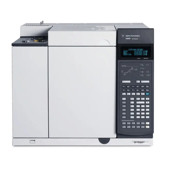
Inlets Oven Operating panel (display, status indicators, and Detectors keyboard) Power switch Figure 1 Front of the 7890B GC Oven exhaust vent Inlet vents Gas supply connections Electronic cable connections Oven cooling intake Power connection Figure 2 Back of the 7890B GC... -
Page 12: Unpacking
Some detectors may have protective caps for shipping. Remove these caps. If equipped with a side-mounted detector, remove the left side panel to gain access to the detector vent cap. Open the oven door. Remove any packing from inside the oven. Agilent 7890B Installation... -
Page 13: Step 1. Place The Gc On The Bench
Oven exhaust Figure 3 Correct position of the oven exhaust deflector The oven exhaust deflector accepts a 10-cm (4 in.) diameter exhaust duct, and adds about 13 cm to the depth of the GC. Agilent 7890B Installation... -
Page 14: Step 2. Verify Line Voltage, Voltage Settings, And Power Cord
See the examples below. The GC power consumption and requirements depend on the type of oven that you ordered and the country the unit shipped to. Fast oven options 002 and 003 require more power than the standard oven. Agilent 7890B Installation... -
Page 15: Power Cords Available
Table 2 Power cords by country Part number Country Description Wall termination Plug termination 8120-1992 Power Cord, C13 125V 13A NEMA NEMA 5-20P 5-15 HG US 8120-3997 Denmark, Greenland Power Cord, DK/Greenland, C13, AFSNIT 107-2-01 10 amp Agilent 7890B Installation... - Page 16 Power Cord, Japan, C19, 20 amp NEMA L6-20P 8120-6978 Chile Power Cord, Chile, C13, 10 amp CEI 23-16 8120-8619 Australia Power Cord, Australia, 16 amp AS 3112 8120-8620 Great Britain, Hong Power Cord, GB/HK/SG/MY, C19, BS1363 Kong, Singapore, 13 amp Malaysia Agilent 7890B Installation...
- Page 17 China Power Cord PRC Fast GB 1002 8121-0075 Power Cord, US 240V, C19, 15 amp NEMA L6-20P 8121-0161 Israel Power Cord, Israel, C19, 16 amp Israeli SI32 8121-0675 Argentina Power Cord, Argentina, C19, 20 amp AS 3112 Agilent 7890B Installation...
- Page 18 Power Cord, Thai 220V, 15 A, 1.8M, 8121-1787 Brazil Power Cord, Brazil, C19, 16 A, IEC 60906-1 250V Max 8121-1809 Brazil Power Cord, Brazil, C13, 10 A, IEC 60906-1 250V Max 8120-1369 Australia, New Power Cord, Australia/NZ, C13, AS 3112 Zealand 10 amp Agilent 7890B Installation...
-
Page 19: Grounding
Table 1. If the voltage option you ordered is not suitable for your installation, contact Agilent Technologies. Line power cord terminations The power cord termination is determined by the country where the GC is ordered. -
Page 20: Step 3. Connect The Power Cord And Turn On The Gc
Step 3. Connect the power cord and turn on the GC Verify that the power switch is in the Off position. Power switch Figure 4 Power switch location Plug the power cord into the back of the GC and the power outlet. Attach power cord here Agilent 7890B Installation... - Page 21 Installing the GC Turn on the GC. The self-test diagnostic tests run automatically. If the screen displays Power on successful, continue with the installation procedure. AGILENT 7890B B.XX.XX [XXX] Power on successful Actual Setpoint Agilent 7890B Installation...
-
Page 22: Step 4. Connect Gases And Traps
CGA 590, 125 psig max (8.6 bar), Air 5183-4645 * For 1/4-inch tubing, purchase a 1/4-inch to 1/8-inch adapter, U.S. only. Confirm that the outlet fitting of the regulator is 1/8-inch Swagelok. If not, install the appropriate adapter fitting. Wrap Agilent 7890B Installation... - Page 23 NPT pipe thread fitting. Install the regulator onto the compressed gas cylinder main fitting. • Check the thread type. Some regulators use left-hand thread fittings. For left-handed threads, the nut will have a groove in it. Groove indicates left-hand thread Agilent 7890B Installation...
-
Page 24: Connect The Tubing To The Gas Source
1/4-inch tubing with appropriate hardware. See the Agilent GC, GC/MS, and ALS Site Preparation Guide for part numbers. Turn off all gases at their sources. Measure the length of tubing needed to connect the gas supply outlet to the inlet Agilent 7890B Installation... -
Page 25: Install Traps
On/Off valves. See also the Site Preparation Guide. Tank valve Two-stage regulator On/Off valve Gas Clean Filter system On/Off valve Gas supply Figure 6 Plumbing the gas supplies Cut the tubing to length with a tubing cutter. Agilent 7890B Installation... -
Page 26: Supplied Fittings
Inlet and detector EPC flow modules are mounted very close together across the back of the GC. See Figure 7. Figure 7 Plumbing flow modules Be sure to vent uncombusted hydrogen to a fume hood or other WA RNING safe location. Agilent 7890B Installation... - Page 27 Purge the supply lines for a few minutes before connecting them to the GC flow modules. Inlet flow module Front inlet EPC module Carrier gas connection Back inlet EPC module Carrier gas connection Figure 8 Inlet flow module Agilent 7890B Installation...
- Page 28 60 mm = ~ 2 1/4 inches 107 mm = ~ 4 1/4 inches 33 mm = ~ 1 5/16 inches 33 mm = ~ 1 5/16 inches Figure 9 Tee for inlet flow module Detector flow module Figure 10 Detector flow module Agilent 7890B Installation...
- Page 29 Side panel detector connections If the GC is equipped with a side-mounted TCD or μECD, attach the carrier gas to the single gas connection at the back of the side mount enclosure. (For TCD, an internal Tee feeds the reference gas or input.) Agilent 7890B Installation...
-
Page 30: Install Aux Epc Module Frits For Your Application
• Always use new O-rings (part number 5181-3344, O-rings, 6/pk). • Install tubing and connectors as needed for each additional gas supply required. • Do not install an external flow restrictor. • For other restrictor recommendations, see the Advanced Operation manual. Agilent 7890B Installation... -
Page 31: Install Hydrogen Sensor Calibration Gas
To hydrogen sensor Calibration gas cylinder 1/8-inch copper tubing, cut to length needed Gas cylinder stand Turn the pressure regulator completely off and set the output pressure as low as possible (full CCW). Pressure adjustment On/Off Tank pressure gage Agilent 7890B Installation... - Page 32 Install the calibration gas cylinder into the stand and secure using the screw. Turn on the supply pressure at the pressure regulator. (You will adjust it later.) Check for leaks in the fittings using a leak detection fluid. Correct any leaks. Agilent 7890B Installation...
-
Page 33: Step 5. Leak Test All Connections And Set Source Pressures
Perform a pressure drop test. Turn off the GC. Set the regulator pressure to 415 kPa (60 psi). Fully turn the regulator pressure adjustment knob counterclockwise to shut the valve. Agilent 7890B Installation... - Page 34 (1 psi), there is a leak in the external connections. Use the leak detector to check each fitting for leaks. See Figure Figure 12 Locations to check for leaks Correct leaks by tightening the connections. Retest the connections; continue tightening until all connections are leak-free. Agilent 7890B Installation...
-
Page 35: Set Source Gas Pressures
Air for FID, FPD Detectors 550 kPa (80 psi) Hydrogen Detectors 410 kPa (60 psi) Makeup gas Detectors 410 kPa (60 psi) TCD Reference 410 kPa (60 psi) Air for valve actuators Valves 345 kPa (50 psi) Agilent 7890B Installation... -
Page 36: Step 6. Vent Μecd Or Uncombusted Hydrogen To A Fume Hood
Route the tubing out the back of the GC, following the same path as for the uECD vent tubing. The other detectors (FID and FPD) combust any hydrogen carrier gas. Agilent 7890B Installation... -
Page 37: Step 7. Connect Cryogenic Cooling (If Present)
Flared or AN tubing fittings are commonly used to connect the liquid supply tubing to the cryo coolant tank. Check with the supplier of the coolant before plumbing to be sure you have the correct fittings. Agilent 7890B Installation... -
Page 38: Connecting Liquid Carbon Dioxide
Prepare enough tubing to reach from the supply tank to this fitting. See Figure Cryogenic cooling valve fitting Figure 13 Location of cryogenic cooling valve Connect the supply tubing to the liquid CO tank outlet with the fitting recommended by the supplier. Agilent 7890B Installation... - Page 39 Installing the GC Use a Swagelok fitting to connect the supply tubing to the cryogenic valve inlet. Agilent 7890B Installation...
-
Page 40: Connecting Liquid Nitrogen
Figure 14 N cryogenic cooling valve connections Connect the supply tubing to the liquid N tank outlet with the fitting recommended by the supplier. Use a Swagelok fitting to connect the supply tubing to the cryogenic valve inlet. Agilent 7890B Installation... -
Page 41: Connecting Air To The Multimode Inlet
GC. Prepare enough tubing to reach from the supply to this outlet. Connect the supply tubing to the air supply outlet with the fitting recommended by the supplier. Use a Swagelok fitting to connect the supply tubing to the cryogenic valve input fitting. Agilent 7890B Installation... -
Page 42: Step 8. Connect Valve Actuator Air (If Present)
Turn off the air supply at the source. If needed, shorten the supplied plastic tubing using a sharp knife. Connect the tubing to the air source using a 1/4-inch Swagelok nut and ferrules. See Figure Plastic tubing for actuator air Figure 15 Valve actuator air tubing Agilent 7890B Installation... -
Page 43: Step 9. Install Inlet Checkout Parts
To Prepare for Chromatographic Checkout. Also see the procedures listed in Maintaining Your GC. Split/splitless inlet Multimode inlet If installing a GC/MS system, refer to the GC/MS installation manuals for the correct inlet hardware to install, as needed. Agilent 7890B Installation... -
Page 44: Step 10. Install Als, If Ordered
Place the solvent vials into the injector turret. For details on the solvent needed, see the Operation Manual: • FID checkout • checkout • checkout (Japan) • NPD checkout • TCD checkout • μECD checkout Agilent 7890B Installation... -
Page 45: Step 11. Connect The External Cables
If using an ALS, connect it to the GC using the following connectors: SAMPLER 1 Optional. An injector, usually the front injector. (For 7693A/7650, the GC automatically senses the injector location. For a 7683 injector, typically configure this injector as INJ1.) Agilent 7890B Installation... - Page 46 “Using the Remote Start/Stop Cable” on page 78 for more detail. EVENT connector This connector provides two passive contact closures and two 24-volt outputs for controlling external devices. The outputs are controlled by valve drivers 5 through 8. Agilent 7890B Installation...
- Page 47 BCR/RA connector This connector is reserved for the optional G3494B RS-232 Barcode Reader. Refer to the GC Operation Manual. LAN connector Standard Local Area Network (LAN) connector, for communication with data systems and other devices via TCP/IP. Agilent 7890B Installation...
-
Page 48: Connecting Cables
Table 7 Cabling requirements 7890 Series GC connected to: Required Cable(s) Part number Samplers 7693A Automatic Liquid Sampler Injector cable or tray cable G4514-60610 7650 Automatic Liquid Sampler Injector cable G4514-60610 Agilent 7890B Installation... - Page 49 Valve pulser module power supply cable (includes G1580-60730 green EVENT label) Stream selection valves See documentation accompanying the valve Gas sampling valves (external) External valve cable (includes green EVENT label) G1580-60710 Cable, networking CAT 5, 25 feet 8121-0940 Cable, LAN, crossover 5183-4648 Agilent 7890B Installation...
-
Page 50: Labeling Bcd And Event Cables
For network (LAN) operation, the GC needs an IP address. It can be entered directly from the keyboard (recommended if using an Agilent data system) or obtained from a DHCP server (not recommended). In either case, see your LAN administrator. Agilent 7890B Installation... - Page 51 GC control software will be unable to connect to the GC. Turn on the GC. Press [Options]. Scroll to Communications and press [Enter]. Scroll to Enable DHCP and press [On/Yes]. When prompted, turn the GC off and then on again. Agilent 7890B Installation...
-
Page 52: Gc / Ms / Agilent Data System / Als
Cables for a typical GC/MSD or GC/MS system Number Part number and description G1530-60930, 2-m APG remote cable, 9-pin male/9-pin male 8121-0940, Cable, LAN, 25 foot Additional cabling configurations For additional cabling configurations, see Appendix B, “Cabling Diagrams and Remote Start/Stop." Agilent 7890B Installation... -
Page 53: Step 12. Finish Configuring Communications
Parts Finder data, and MS-friendly features such as the MS Vent method as follows: Configure the MS transfer line. Press [Aux Temp #] and check if the MSD transfer line has been configured yet. When configured, the MS transfer Agilent 7890B Installation... - Page 54 Available entries include: Second source, HV Pump, and Rough pump. For MS instruments with only one source, set Second source to NOT PRESENT. Scroll to Serial # and input the MS serial number. Press [Enter]. Agilent 7890B Installation...
- Page 55 Open the online instrument session and confirm communications between the instruments and the data system. After establishing GC-MS communications and configuration, next configure GC-HS communications, if applicable, or continue to “Step 4. Connect gases and traps”. Agilent 7890B Installation...
-
Page 56: Configuring Gc-Ms Communications (5877B)
Injector] if it is connected to the GC back inlet. Scroll to No Headspace, then press [Mode/Type]. A list of headspace sampler models appears. Scroll to the correct one, then press [Enter]. Press [Options], then select Communications. Agilent 7890B Installation... - Page 57 LAN. Verify all LAN cable connections. After GC installation, complete HS configuration. Refer to the HS control software help and the HS manuals for information on the configuration options. Agilent 7890B Installation...
-
Page 58: Step 13. Calibrate The Hydrogen Sensor
30 mL/min. Remove the flow meter and close the oven door. After setting the flow, continue with installation while the calibration completes. (Calibration takes about 5 minutes total time). Hydrogen sensor calibration will not interfere with any other steps. Agilent 7890B Installation... -
Page 59: Step 14. Configure The Date/Time, Pressure Units, And The Checkout Column
Aux and PCM channels, and detectors. When a detector is selected, the outlet end of the column is controlled at 0 psig for the FID, TCD, FPD, NPD, and uECD or vacuum for the MSD. Agilent 7890B Installation... - Page 60 MSD transfer line heated by an auxiliary zone, valves in a separately-heated valve box or other configurations. Select the appropriate Thermal zone and press [Enter]. This completes configuration for a single capillary column. Also see the Operation manual for more information about configuring columns. Agilent 7890B Installation...
-
Page 61: Step 15. Install The Checkout Column To The Inlet And Condition
Refer to the conditioning instructions that shipped with the checkout column. Note the oven temperature, average velocity or flow, and so on. Leave the detector end of the column unattached. Set the oven temperature and inlet flow conditions specified for conditioning the column. Agilent 7890B Installation... - Page 62 Condition for the time given in the column’s instructions. Cool the oven. Leave the carrier gas on. If using a flammable carrier gas (hydrogen), continue to vent the column exhaust to a fume hood. (Prevent hydrogen gas accumulation in the GC.) Agilent 7890B Installation...
-
Page 63: Step 16. Bakeout The Detector
Turn the detector gases on. Light the flame, if appropriate. Heat the detector to the temperature given in the bakeout instructions, and hold at temperature for the time given in the instructions. Agilent 7890B Installation... -
Page 64: Step 17. Cool The Detector And Complete Column Installation
Maintaining Your GC manual. Refer to the section for your specific detector type. • • • • μECD • FPD+ Connect the free end of the checkout column to the detector, as described in Maintaining Your GC. Agilent 7890B Installation... -
Page 65: Step 18. If Appropriate, Update Firmware
Open file <D:>/index.html, where <D:> is the name of the DVD drive. Click the GC Firmware Update Tool icon. Read the instructions, then install the utility as described. Check the GC firmware version. On the GC keyboard, press [Status][Clear]. The display shows the current firmware version. Agilent 7890B Installation... -
Page 66: Pids
• If the system includes a PCM module for controlling the backpressure to a headspace sampling loop, use the Firmware Update Utility or Instrument Utilities to update the PCM module PID constants according to the application instructions. (Required) Agilent 7890B Installation... -
Page 67: Step 19. Transfer The Checkout Sample To A Screw-Top Sample Vial
Use a pipette to transfer the sample to a 2-mL screw-top vial. (If using an ALS, use a vial suitable for the ALS turret or tray.) Agilent 7890B Installation... -
Page 68: Step 20. When The System Stabilizes, Run One Injection
When the GC becomes Ready (Not ready light turns off), make the injection and start the run. For an ALS injection, press [Start] on the GC or in the data • system, as appropriate. For a manual injection, inject the sample and press [Start]. • Agilent 7890B Installation... -
Page 69: Step 21. Evaluate Results
Installing the GC Step 21. Evaluate Results Compare the chromatogram you generated with the one in the checkout procedure. There should be a close resemblance. Agilent 7890B Installation... -
Page 70: Prepare For The Next Analysis
• Install the desired column and condition it per the manufacturer’s recommendations. • Configure the GC to match any hardware or gas type changes (columns, liners, carrier or makeup gas types, and so on). • Load or create the desired method. Agilent 7890B Installation... - Page 71 Agilent 7890B Gas Chromatograph Installation and First Startup Making Swagelok Connections Making Swagelok Connections Using a Swagelok Tee The gas supply tubing is attached with Swagelok fittings. If you are not familiar with Swagelok connections, review the following procedures. Agilent Technologies...
-
Page 72: A Making Swagelok Connections
Do not use an inlet or detector fitting. Strong forces are required to properly set the ferrules, and damage to an inlet or Do not detector fitting is very costly to repair. Push the tubing into the stainless steel plug (see Figure 18). Agilent 7890B Installation... - Page 73 Push the tube fully into the plug, then withdraw it approximately 1 to 2 mm (see Figure 19). Front ferrule Insert tubing fully Back ferrule Withdraw tubing 1-2 mm Tighten nut Figure 19 Insert the tubing Finger-tighten the nut. Agilent 7890B Installation...
- Page 74 Both correctly- and incorrectly-swaged connections are shown in Figure 22. Note that the end of the tubing in a correctly-swaged fitting is not crushed and does not interfere with the action of the ferrules. Figure 22 Completed fitting Agilent 7890B Installation...
-
Page 75: Using A Swagelok Tee
Tee with a Swagelok fitting. See Figure Tee fitting Nut and ferrules Figure 23 Swagelok tee Measure the distance from the Tee to the instrument fittings. Attach copper tubing to the open Tee ends with Swagelok fittings. Agilent 7890B Installation... - Page 76 Making Swagelok Connections Agilent 7890B Installation...
- Page 77 Agilent 7890B Gas Chromatograph Installation and First Startup Cabling Diagrams and Remote Start/Stop Using the Remote Start/Stop Cable Multi-instrument Cabling Examples Cable Diagrams This section lists cabling requirements and connection diagrams that apply to less common or specialized GC installations.
-
Page 78: Using The Remote Start/Stop Cable
2.2 V. Higher leakage current may cause the state to be interpreted as a low. Over-voltage protection: APG Remote connections are clamped by a zener diode to 5.6 V. Exceeding this voltage will damage the circuit (GC logic board). Agilent 7890B Installation... - Page 79 Gas Saver. This function is not needed by Agilent autosampler systems. Ready (High True) If the Ready line is high (> 2.2 VDC) then the system is ready for next analysis. Receiver is any sequence controller. Agilent 7890B Installation...
- Page 80 (for example, stop run, abort or finish, and stop injection). Receiver is any module performing runtime-controlled activities. Normally this line is not connected, if the GC oven program is used to control the method Stop time. APG Remote timing diagram Prepare H Start Stop Ready Agilent 7890B Installation...
-
Page 81: Multi-Instrument Cabling Examples
White Black 24 V Out 2 Start Ground Shut down Green White Ground Reserved Brown Orange Contact 1 Power on Blue Green Contact 1 Ready Orange Brown Contact 2 Stop Yellow Blue Contact 2 Start Request Violet Agilent 7890B Installation... -
Page 82: Gc / 3395A/3396B Integrator / Als
Cabling Diagrams and Remote Start/Stop GC / 3395A/3396B Integrator / ALS GC/ALS 1. APG Remote Cable, 2. Analog cable, 2-m, 6 pin, 03396-61010 G1530-60570 Number Part number and description 03396-61010, 2-m APG remote cable, 9-pin/15-pin G1530-60570, 2-m Analog cable, 6-pin Agilent 7890B Installation... -
Page 83: Gc / 3396C Integrator / Als
GC / 3396C Integrator / ALS GC/ALS 1. APG Remote Cable, 2. Analog cable, 2-m, 6 pin, G1530-60930 G1530-60570 Number Part number and description G1530-60930, 2-m APG remote cable, 9-pin male/9-pin male G1530-60570, 2-m Analog cable, 6-pin Agilent 7890B Installation... -
Page 84: Example: Using A Y-Cable In A Setup (Gc/Msd/Data System/Headspace Sampler)
1. LAN cable 8121-0940 1. LAN cable 1. LAN cable 1. LAN cable 8121-0940 8121-0940 8121-0940 GC/ALS Computer 2. APG Remote Y-Cable, G1530-61200 Number Part number and description G1530-61200, 2-m Y-cable, remote start/stop 8121-0940, Cable, LAN, 25 foot Agilent 7890B Installation... -
Page 85: Gc / External Events (Unspecified, Non-Agilent Instrument)
150 mA output Black Ground Ground White Relay contact closures (normally open) Contact closure 1 48V AC/DC, 250 mA Orange Contact closure 1 Green Contact closure 2 48 V AC/DC, 250 mA Brown or violet Contact closure 2 Blue Agilent 7890B Installation... -
Page 86: Cable Diagrams
Table 10 Analog cable, general use, output connections Connector 1 Connector 2, wire color Signal Brown or violet Not used White 0 to 1 V, 0 to 10 V (–) Not used Black 1 V (+) Blue 10 V (+) Shell Orange Ground Agilent 7890B Installation... -
Page 87: Agilent Analog Signal Cable, G1530-60570
The pin assignments for the remote start/stop cable are listed in Table Table 11 Remote start/stop cable connections Connector 1, 9-pin male Connector 2, wire color Signal Black Digital ground White Prepare (low tone) Start (low tone) Green Start relay (closed during start) Agilent 7890B Installation... -
Page 88: Agilent Apg Remote Start/Stop Cable, 03396-61010
Open circuit Agilent APG remote start/stop cable, 03396-61010 Synchronizes the GC with an Agilent integrator. Additional cables may be used to add more instruments (up to 10 total). Figure 25 Remote start/stop cable, GC to Agilent integrator Agilent 7890B Installation... -
Page 89: Agilent Apg Remote Start/Stop Cable, G1530-60930
Additional cables may be used to add more instruments (up to 10 total). G1530-60930 Figure 26 Remote start/stop cable, GC to Agilent instrument Agilent remote start/stop Y-cable, G1530-61200 Synchronizes the GC with another 2 Agilent instruments. Figure 27 Remote start/stop cable, GC to Agilent instrument Agilent 7890B Installation... -
Page 90: Bcd Cable, G1530-60590
48 V AC/DC, 250 mA LS digit 0 LS digit 1 LS digit 2 LS digit 3 MS digit 0 Ground Shield Chassis ground When used for BCD input, apply label G1580-87100 to identify the cable for BCD use. Agilent 7890B Installation... -
Page 91: Bcd Cable, G1530-61100
The pin assignments for this connector are listed in Table Table 13 BCD cable connections Connector 1 Pin Connector 2 Pin Ribbon Cable Wire Color Brown Orange Yellow Green Blue Violet Gray White 2, 8 Black Brown Orange Yellow Green Blue Agilent 7890B Installation... -
Page 92: External Event Cable, G1530-60590
The external event cable has two passive relay contact closures with two 24-volt control outputs. Devices connected to the passive contact closures must be connected to their own power sources. The pin assignments for this cable are listed in Table Agilent 7890B Installation... -
Page 93: External Valve Cable, G1580-60710
Supplies power for certain valve applications. Connector 1 pin Wire color Connector and pin Function Yellow V5 pin 1 24 V, 150 mA max. Black V6 pin 1 24 V, 150 mA max. V5 pin 2 Ground White V6 pin 2 Ground Agilent 7890B Installation... -
Page 94: Pulser Module Power Supply Cable, G1580-60730
Agilent Technologies Pulser module power supply cable, G1580-60730 Supplies power for a PDHID pulser module. Connector 1 Connector 2 Connector 3 Connector 1 pin Wire color Connector and pin Function Yellow Black White Connector 3 pin 1 Ground Orange Connector 2 pin 1...
Need help?
Do you have a question about the 7890B and is the answer not in the manual?
Questions and answers