Table of Contents
Advertisement
Quick Links
Advertisement
Table of Contents

Related Manuals for DIGITAL-LOGIC MSM800SEV/SEL

Summary of Contents for DIGITAL-LOGIC MSM800SEV/SEL
- Page 1 DETAILED TECHNICAL USER MANUAL FOR: PC/104 plus MSM800SEV/SEL MSM800BEV MSM800XEV/XEL Nordstrasse 11/F CH - 4542 Luterbach Tel.: ++41 (0)32 681 58 00 Fax: ++41 (0)32 681 58 01 Email: support@digitallogic.com Homepage: http://www.digitallogic.com...
- Page 2 DIGITAL-LOGIC AG. The software described herein, together with this document, are furnished under a license agreement and may be used or copied only in accordance with the terms of that agreement.
-
Page 3: Table Of Contents
MSM800LVDSCON ....................... 32 2.8.3. MSM800DVICON ........................33 2.8.4. MSM800CON ........................34 2.9. MSM800SEV/SEL Incompatibilities to a Standard PC/AT ............35 2.9.1. PC104 BUS / ISA BUS ......................35 2.9.2. ISA-Incompatibility with ISA-PCCARD-Controller ..............36 2.9.3. ISA-Incompatibility with 16bit I/O Transfer with FPGA-Decoder ........... 36 2.9.4. - Page 4 DVICON Resolution........................66 6.4. Flat Panel Functional Description ....................67 ................68 ESCRIPTION OF THE CONNECTORS 7.1. Top Side of the MSM800SEV/SEL V2.1/V2.2................69 7.2. Bottom Side of the MSM800SEV V2.1/V2.2................70 7.3. Top Side of the MSM800BEV V1.1 ....................71 7.4.
-
Page 5: Preface
Product advances mean that some specifications may have changed. DIGITAL-LOGIC AG assumes no responsibility for any inaccuracies, or the consequences thereof, that may appear in this manual. Furthermore, DIGITAL-LOGIC AG does not accept any liability arising from the use or application of any circuit or product described herein. -
Page 6: Recycling Information
DIGITAL-LOGIC AG), wrong connection, wrong information or as a result of service or modification by anyone other than DIGITAL-LOGIC AG. Nor if the user has insufficient knowledge of these technologies or has not consulted the product manuals or the technical support of DIGITAL-LOGIC AG and therefore the product has been damaged. -
Page 7: Explanation Of Symbols
DIGITAL-LOGIC AG MSM800SEV/SEL/BEV/XEV/XEL Detailed Manual V1.7 1.8. Explanation of Symbols CE Conformity This symbol indicates that the product described in this manual is in compliance with all applied CE standards. Caution, Electric Shock! This symbol and title warn of hazards due to electrical shocks (> 60V) when touching products or parts of them. -
Page 8: Applicable Documents And Standards
DIGITAL-LOGIC AG MSM800SEV/SEL/BEV/XEV/XEL Detailed Manual V1.7 1.9. Applicable Documents and Standards The following publications are used in conjunction with this manual. When any of the referenced specifications are superseded by an approved revision, that revision shall apply. All documents may be obtained from their respective organizations. -
Page 9: For Your Safety
1.11. RoHS Commitment DIGITAL-LOGIC AG is committed to develop and produce environmentally friendly products according to the Restriction of Hazardous Substances (RoHS) Directive (2002/95/EC) and the Waste Electrical and Electronic Equipment (WEEE) Directive (2002/96/EC) established by the European Union. -
Page 10: Rohs Compatible Product Design
Components and sub-assemblies are not subject to product compliance. In other words, since DIGITAL-LOGIC does not deliver ready-made products to end users the WEEE directive is not applicable for DIGITAL-LOGIC. Users are nevertheless encouraged to... -
Page 11: Swiss Quality
Network, IQNet, and co-operation contracts/agreements with accredited partners. www.sqs.ch The SQS Certificate ISO 9001:2000 has been issued to DIGITAL-LOGIC AG, the entire company, in the field of development, manufacturing and sales of embedded computer boards, embedded computer modules and computer systems. The certification is valid for three years at which time an audit is performed for... -
Page 12: Overview
EEPROM for setup and configuration UL approved parts Watchdog 2.2. Unique Features MSM800SEV/SEL The MSM800SEV/SEL includes all standard PC/AT functions plus unique enhancements, such as: LAN Ethernet, INTEL 82551ER (or on request [optional] 82551QM) LPC to ISA Bridge SODIMM DDR-Memory holder (128-1024MByte) 2.3. -
Page 13: Block Diagrams
DIGITAL-LOGIC AG MSM800SEV/SEL/BEV/XEV/XEL Detailed Manual V1.7 2.5. Block Diagrams 2.5.1. MSM800SEV... -
Page 14: Msm800Bev
DIGITAL-LOGIC AG MSM800SEV/SEL/BEV/XEV/XEL Detailed Manual V1.7 2.5.2. MSM800BEV... -
Page 15: Msm800Xev
DIGITAL-LOGIC AG MSM800SEV/SEL/BEV/XEV/XEL Detailed Manual V1.7 2.5.3. MSM800XEV... -
Page 16: Msm800 Sev/Sel, Bev/Bel, Xev/Xel Specifications
DIGITAL-LOGIC AG MSM800SEV/SEL/BEV/XEV/XEL Detailed Manual V1.7 2.6. MSM800 SEV/SEL, BEV/BEL, XEV/XEL Specifications Geode LX800 CPU Core Supply 1.8V very low powered Mode Real/Protected Compatibility 8086 – P5 Word Size 32bits Secondary Cache – Physical Addressing 32 lines Virtual Addressing 16GBytes... - Page 17 DIGITAL-LOGIC AG MSM800SEV/SEL/BEV/XEV/XEL Detailed Manual V1.7 Mass Storage Floppy disk interface, for max. 1 floppy with 26pin connector E-IDE interface, AT-type, for max. 2 hard disks, 44pin connector, for 1.3, 1.8 and 2.5" hard disks with 44 pins IDE Standard AT Interfaces...
- Page 18 DIGITAL-LOGIC AG MSM800SEV/SEL/BEV/XEV/XEL Detailed Manual V1.7 Operating Environment Relative humidity 5-90% non-condensing Vibration 5 to 2000Hz, 0.1G Shock Temperature MSM800SEV/SEL Operating standard version: Without heat sink: 0° C to +60°C With small heat sink 807041: -25° C to +70°C Operating extended version:...
-
Page 19: Examples Of Ordering Codes
DIGITAL-LOGIC AG MSM800SEV/SEL/BEV/XEV/XEL Detailed Manual V1.7 2.7. Examples of Ordering Codes Part / Option Part Nr. Description MSM800SEL 802105 Low cost version without: RTC-battery MSM800SEV 802100 Standard version with: LPC-Bridge MSM800BEV 802110 Standard version with: full ISA-16bit support and PCI-ISA-Bridge... -
Page 20: Dimensions And Diagrams
DIGITAL-LOGIC AG MSM800SEV/SEL/BEV/XEV/XEL Detailed Manual V1.7 2.8. Dimensions and Diagrams 2.8.1. MSM800SEV/SEL/BEV/XEV/XEL Board / Version Unit: Tolerance: Date / Author MSM800SEV/BEV V2.1 mm (millimeter) + / - 0.1mm 19.03.2008 / BRR Board Dimensions... - Page 21 DIGITAL-LOGIC AG MSM800SEV/SEL/BEV/XEV/XEL Detailed Manual V1.7 Board / Version Unit: Tolerance: Date / Author MSM800XEV mm (millimeter) + / - 0.1mm 19.03.2008 / BRR...
- Page 22 DIGITAL-LOGIC AG MSM800SEV/SEL/BEV/XEV/XEL Detailed Manual V1.7 Top of board with heat sink (Option 807041) and battery (SEV/BEV only) Board profile with heat sink (Option 807041) and battery (SEV/BEV only)
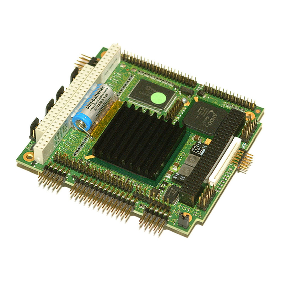
- Page 23 DIGITAL-LOGIC AG MSM800SEV/SEL/BEV/XEV/XEL Detailed Manual V1.7 Top of board with heat sink (Option 807041) and battery, 3D perspective (SEV/BEV/XEV only) Bottom of board, 3D perspective, including the CompactFlash Option...
- Page 24 DIGITAL-LOGIC AG MSM800SEV/SEL/BEV/XEV/XEL Detailed Manual V1.7 MSM800SEV/BEV, 3D perspective Top of Board, with heat sink (Option 807041) Bottom of board...
- Page 25 DIGITAL-LOGIC AG MSM800SEV/SEL/BEV/XEV/XEL Detailed Manual V1.7 MSM800SEL, 3D perspective Top of board, with heat sink (Option 807041) Bottom of board...
- Page 26 DIGITAL-LOGIC AG MSM800SEV/SEL/BEV/XEV/XEL Detailed Manual V1.7 MSM800XEL, 3D perspective Top of board Bottom of board...
- Page 27 DIGITAL-LOGIC AG MSM800SEV/SEL/BEV/XEV/XEL Detailed Manual V1.7 MSM800XEV, 3D perspective Top of board, with heat sink (Option 807041) Bottom of board...
- Page 28 DIGITAL-LOGIC AG MSM800SEV/SEL/BEV/XEV/XEL Detailed Manual V1.7 MSM800BEV/XEV Top of board, with heat sink (Option 807042)
- Page 29 DIGITAL-LOGIC AG MSM800SEV/SEL/BEV/XEV/XEL Detailed Manual V1.7...
- Page 30 DIGITAL-LOGIC AG MSM800SEV/SEL/BEV/XEV/XEL Detailed Manual V1.7 MSM800BEV/XEV Top of board, with heat sink (Option 807043)
- Page 31 DIGITAL-LOGIC AG MSM800SEV/SEL/BEV/XEV/XEL Detailed Manual V1.7...
-
Page 32: Msm800Lvdscon
DIGITAL-LOGIC AG MSM800SEV/SEL/BEV/XEV/XEL Detailed Manual V1.7 2.8.2. MSM800LVDSCON Board / Version Unit: Tolerance: Date / Author MSM800-LVDSCON V0.1 mm (millimeter) + / - 0.1mm 25.10.2006 / BRR... -
Page 33: Msm800Dvicon
DIGITAL-LOGIC AG MSM800SEV/SEL/BEV/XEV/XEL Detailed Manual V1.7 2.8.3. MSM800DVICON Board / Version Unit: Tolerance: Date / Author MSM800-DVICON V0.1 mm (millimeter) + / - 0.1mm 25.10.2006 / BRR... -
Page 34: Msm800Con
DIGITAL-LOGIC AG MSM800SEV/SEL/BEV/XEV/XEL Detailed Manual V1.7 2.8.4. MSM800CON Board / Version Unit: Tolerance: Date / Author MSM800-CON V1.0 mm (millimeter) + / - 0.1mm 25.10.2006 / BRR... -
Page 35: Msm800Sev/Sel Incompatibilities To A Standard Pc/At
DIGITAL-LOGIC AG MSM800SEV/SEL/BEV/XEV/XEL Detailed Manual V1.7 2.9. MSM800SEV/SEL Incompatibilities to a Standard PC/AT 2.9.1. PC104 BUS / ISA BUS An onboard LPC to ISA-bridge makes it possible to expand the functionality of the board with additional PC/104 cards. Unfortunately, because of the transformation from LPC to ISA it is not possible to realize a 16bit access. This does not mean that these cards cannot be used, but that the 16bit access is divided into two. -
Page 36: Isa-Incompatibility With Isa-Pccard-Controller
DIGITAL-LOGIC AG MSM800SEV/SEL/BEV/XEV/XEL Detailed Manual V1.7 2.9.2. ISA-Incompatibility with ISA-PCCARD-Controller Experience shows that ATA-Drives controlled in an ISA-PCMCIA Controller do not work. Solution: Use a PCCARD-Controller on the PCI-Bus 2.9.3. ISA-Incompatibility with 16bit I/O Transfer with FPGA-Decoder Our experience shows that 16bit I/O-transfers decoded with a FPGA do not always work correctly. Each case must be tested. -
Page 37: Thermoscan
DIGITAL-LOGIC AG MSM800SEV/SEL/BEV/XEV/XEL Detailed Manual V1.7 2.11. Thermoscan MSM800SEV V1.2 with small heat sink (OS: MSDOS promt) t [min] [MHz] P01 [° C] P02 [° C] R11 [° C] R12 [° C] 61.9 52.1 56.2 62.6 MSM800SEV V2.1 with small heat sink (OS: MSDOS... - Page 38 DIGITAL-LOGIC AG MSM800SEV/SEL/BEV/XEV/XEL Detailed Manual V1.7 MSM800XEV V1.0 with small heat sink t [min] [MHz] R11 [° C] R12 [° C] 47.1 53.8 MSM800XEL V1.0 t [min] [MHz] P01 [° C] R11 [° C] R12 [° C] 54.2 53.7 49.9...
-
Page 39: High Frequency Radiation (To Meet En55022)
DIGITAL-LOGIC AG MSM800SEV/SEL/BEV/XEV/XEL Detailed Manual V1.7 2.12. High Frequency Radiation (to meet EN55022) Since the PC/104 CPU modules are very highly integrated embedded computers, peripheral lines are not protected against radiation from the high frequency spectrum. To meet a typical EN55022 requirement, all peripherals that go outside of the computer case must be externally filtered. -
Page 40: Battery Lifetime
DIGITAL-LOGIC AG MSM800SEV/SEL/BEV/XEV/XEL Detailed Manual V1.7 2.13. Battery Lifetime Note... The RTC back-up battery is assembled onboard only for the MSM800SEV/BEV/XEV systems. Battery specifications Lowest temp. Nominal temp. Highest temp. -40° C +20° C +85° C Manufacturer Type ER10280 Capacity versus temp. -
Page 41: Bus Signals
DIGITAL-LOGIC AG MSM800SEV/SEL/BEV/XEV/XEL Detailed Manual V1.7 3. B IGNALS 3.1. PC104 Bus Note... Not all of the signals are available on this board (please see Chapter 7 for a description of the connectors). AEN, output Address Enable: used to degate the microprocessor and other devices from the I/O channel to allow DMA transfers to take place. - Page 42 DIGITAL-LOGIC AG MSM800SEV/SEL/BEV/XEV/XEL Detailed Manual V1.7 IRQ [10, 12, 14, 15], input These signals are used to tell the microprocessor that an I/O device needs attention. An interrupt request is generated when an IRQ line is raised from low to high. The line must be held high until the microprocessor acknowledges the interrupt request.
-
Page 43: Pc104+ Bus
DIGITAL-LOGIC AG MSM800SEV/SEL/BEV/XEV/XEL Detailed Manual V1.7 /SMEMR, input/output These signals instruct the memory devices to drive data onto the data bus for the first MByte. /SMEMR is active on all memory read cycles. /SMEMR may be driven by any microprocessor or DMA controller in the system. - Page 44 DIGITAL-LOGIC AG MSM800SEV/SEL/BEV/XEV/XEL Detailed Manual V1.7 FRAME* Frame is driven by the current master to indicate the start of a transaction and will remain active until the final data cycle. TRDY* Target Ready indicates the selected device’s ability to complete the current data cycle of the traansaction.
-
Page 45: Expansion Bus
DIGITAL-LOGIC AG MSM800SEV/SEL/BEV/XEV/XEL Detailed Manual V1.7 3.3. Expansion Bus The bus currents are as follows: Output Signals D0-D16 8 mA 8 mA A0-A23 8 mA 8 mA MR, MW, IOR, IOW, RES, ALE, AEN, C14 8 mA 8 mA DACKx, DRQx, INTx, PSx, OPW... -
Page 46: Bios History
DIGITAL-LOGIC AG MSM800SEV/SEL/BEV/XEV/XEL Detailed Manual V1.7 4. BIOS H ISTORY This BIOS history is for the MSM800XEV/XEL. This BIOS history is for the following products: MSM800SEV/SEL, MSM800BEV, MPCV800, MSEP800, SM800 Version Date Status Modifications 1.22 09.2007 Initial Release E47 support 1.24... -
Page 47: Detailed System Description
DIGITAL-LOGIC AG MSM800SEV/SEL/BEV/XEV/XEL Detailed Manual V1.7 5. D ETAILED YSTEM ESCRIPTION This system has a system configuration based on the ISA architecture. Check the I/O and the Memory maps in this chapter. 5.1. Power Requirements The power is connected through the PC/104 power connector; or the separate power connector on the board. -
Page 48: Cpu, Boards And Rams
DIGITAL-LOGIC AG MSM800SEV/SEL/BEV/XEV/XEL Detailed Manual V1.7 5.3. CPU, Boards and RAMs 5.3.1. CPUs of this MICROSPACE Product Processor Type Clock GEODE LX800 National 500MHz 5.3.2. Numeric Coprocessor The numeric coprocessor is always integrated into the Pentium CPUs. 5.3.3. DDRAM Memory on MSM800SEV/SEL/BEV/BEL... -
Page 49: Line Printer Port Lpt1
DIGITAL-LOGIC AG MSM800SEV/SEL/BEV/XEV/XEL Detailed Manual V1.7 5.4.2. Line Printer Port LPT1 A standard bi-directional LPT port is integrated into the MICROSPACE PC. Further information about these signals is available in numerous publications, including the IBM technical reference manuals for the PC and AT computers and from other reference documents. -
Page 50: Speaker Interface
DIGITAL-LOGIC AG MSM800SEV/SEL/BEV/XEV/XEL Detailed Manual V1.7 Floppy Disk Interface Technology Only CMOS drives are supported. This means the termination resistors are 1 KOhm and 5 1/4“-drives are not recommended (TTL interface). The 26pin connector: FFC/FPC 0.3mm thick 1.0mm (0.039") pitch (MOLEX 52030 Series) -
Page 51: Controllers
DIGITAL-LOGIC AG MSM800SEV/SEL/BEV/XEV/XEL Detailed Manual V1.7 5.5. Controllers 5.5.1. Interrupt Controllers An 8259A compatible interrupt controller, within the chipset, provides seven prioritized interrupt levels. Of these, several are normally associated with the board's onboard device interfaces and controllers, and several are available on the AT expansion bus. -
Page 52: Rtc (Real Time Clock)
Connect an external Lithium battery to X33 pin6 (or use the mounted battery). Be sure to use the correct polarity! The battery-backed clock can be set by using the DIGITAL-LOGIC AG SETUP at boot-time. Note… On all MSM800SEL/BEL/XEL boards – the battery must be connected externally! There is no battery assembled onboard. -
Page 53: Bios
DIGITAL-LOGIC AG MSM800SEV/SEL/BEV/XEV/XEL Detailed Manual V1.7 5.7. BIOS 5.7.1. Core BIOS download 5.7.1.1. Before downloading a BIOS Please read through this section carefully and prepare for the download. Make a bootable diskette which includes the following files: Flashrom.com core BIOS xxxxxxxx.yyy Important... -
Page 54: Rom-Bios Sockets
DIGITAL-LOGIC AG MSM800SEV/SEL/BEV/XEV/XEL Detailed Manual V1.7 5.7.2. ROM-BIOS Sockets An EPROM socket with 8bit wide data access normally contains the board’s AT compatible ROM-BIOS. The socket takes a 29F020 EPROM (or equivalent) device. The board's wait-state control logic automatically inserts four memory wait states in all CPU accesses to this socket. The ROM-BIOS sockets occupy the memory area from C0000H through FFFFFh;... - Page 55 DIGITAL-LOGIC AG MSM800SEV/SEL/BEV/XEV/XEL Detailed Manual V1.7 The following table provides a summary of how these areas may be further divided. Beginning Ending Checksum Description RTC and Checksum System Configuration Checksum Value of 10h - 2Dh Standard CMOS Standard CMOS - SystemSoft Reserved...
- Page 56 DIGITAL-LOGIC AG MSM800SEV/SEL/BEV/XEV/XEL Detailed Manual V1.7 CMOS Map continued... Location Description Status Register C Bit 7 = Interrupt Flag Bit 6 = Periodic Interrupt Flag Bit 5 = Alarm Interrupt Flag Bit 4 = Update Interrupt Flag Bits 3-0 = Reserved...
- Page 57 DIGITAL-LOGIC AG MSM800SEV/SEL/BEV/XEV/XEL Detailed Manual V1.7 CMOS Map continued... Location Description Equipment Bits 7-6 = Number of Diskette Drives One diskette drive Two diskette drives 10, 11 = Reserved Bits 5-4 = Primary Display Type Adapter with option ROM CGA in 40 column mode...
- Page 58 DIGITAL-LOGIC AG MSM800SEV/SEL/BEV/XEV/XEL Detailed Manual V1.7 CMOS Map continued... Location Description Byte 0 Bits 7-0 = Lower 8 bits of Cylinders Byte 1 Bits 7-2 = Lower 6 bits of Landing Zone Bits 1-0 = Upper 2 bits of Cylinders...
- Page 59 DIGITAL-LOGIC AG MSM800SEV/SEL/BEV/XEV/XEL Detailed Manual V1.7 CMOS Map continued... Location Description Reserved High Byte of Checksum - Locations 10h to 2Dh Low Byte of Checksum - Locations 10h to 2Dh Extended RAM (kB) detected by POST - Low Byte Extended RAM (kB) detected by POST - High Byte...
-
Page 60: Eeprom Saved Cmos Setup
DIGITAL-LOGIC AG MSM800SEV/SEL/BEV/XEV/XEL Detailed Manual V1.7 5.9. EEPROM saved CMOS Setup The EEPROM has different functions, as listed below: Backup of the CMOS-Setup values. Storing system information (i.e., version, production date, customization of the board, CPU type). Storing user/application values. -
Page 61: Eeprom Memory For Setup
DIGITAL-LOGIC AG MSM800SEV/SEL/BEV/XEV/XEL Detailed Manual V1.7 5.9.1. EEPROM Memory for Setup The EEPROM is used for setup and configuration data, stored as an alternative to the CMOS-RTC. Optionally, the EEPROM setup driver may update the CMOS RTC, if the battery is running down and the checksum error would appear and stop the system. -
Page 62: System I/O Map
DIGITAL-LOGIC AG MSM800SEV/SEL/BEV/XEV/XEL Detailed Manual V1.7 5.10.2. System I/O Map The following table details the legacy I/O range for 000h through 4FFh. Each I/O location has a read/write (R/W) capability. Note the following abbreviations: Unknown or cannot be determined. Read and write the register at the indicated location. No shadow required. - Page 63 DIGITAL-LOGIC AG MSM800SEV/SEL/BEV/XEV/XEL Detailed Manual V1.7 I/O Map Continued… I/O Addr. Function Size R/W Comment If KEL Memory Offset 100h[0] = 1(Emulation- Enabled bit). 060h Keyboard/Mouse - Data Port 8bit If MSR 5140001Fh[0] = 1 (SNOOP bit) and KEL Memory Offset 100h[0] = 0 (Emulation- Enabled bit).
- Page 64 DIGITAL-LOGIC AG MSM800SEV/SEL/BEV/XEV/XEL Detailed Manual V1.7 I/O Map Continued… I/O Addr. Function Size R/W Comment 0CCh Master DMA Address - Channel 7 8bit Yes 16bit values in two transfers. 0CDh No Specific Usage 8bit 0CEh Master DMA Counter - Channel 7 8bit Yes 16bit values in two transfers.
- Page 65 DIGITAL-LOGIC AG MSM800SEV/SEL/BEV/XEV/XEL Detailed Manual V1.7 I/O Map Continued… I/O Addr. Function Size R/W Comment 3F1h Floppy Status R B 8bit RO First Floppy. 3F2h Floppy Digital Out 8bit Shw@ First Floppy. 3F3h No Specific Usage 8bit 3F4h Floppy Cntrl Status 8bit RO First Floppy.
-
Page 66: Vga/Lcd
VESA standards supported Fully compatible with IBM® VGA Driver support for Windows XP, Windows 2000 Note... On the MSM800SEV/SEL, if the LCD ouput is used then the VGA/CRT output will not work. 6.2. Graphic Modes Bios settings: 254MB video memory (shared) Resolution Col. -
Page 67: Flat Panel Functional Description
DIGITAL-LOGIC AG MSM800SEV/SEL/BEV/XEV/XEL Detailed Manual V1.7 6.4. Flat Panel Functional Description The FP connects to the RGB port of the video mixer. LCD Interface: The FP interfaces directly to industry standard 18 or 24bit active matrix thin-film-transistor (TFT). The digital RGB or video data that is supplied by the video logic is converted into a suitable format to drive a wide variety range of panels with variable bits. -
Page 68: Description Of The Connectors
DIGITAL-LOGIC AG MSM800SEV/SEL/BEV/XEV/XEL Detailed Manual V1.7 7. D ESCRIPTION OF THE CONNECTORS The following pages describe the connector pin-out for the MSM800SEV/SEL V2.1/V2.2, MSMBEV V1.1, and MSMXEV/XEL V1.0. Flat cable 44pin IDE is: IDT Terminal for Dual Row (2.00mm grid) and 1.00mm flat cable All others are: IDT Terminal for Dual Row 0.1"... -
Page 69: Top Side Of The Msm800Sev/Sel V2.1/V2.2
DIGITAL-LOGIC AG MSM800SEV/SEL/BEV/XEV/XEL Detailed Manual V1.7 7.1. Top Side of the MSM800SEV/SEL V2.1/V2.2... -
Page 70: Bottom Side Of The Msm800Sev V2.1/V2.2
DIGITAL-LOGIC AG MSM800SEV/SEL/BEV/XEV/XEL Detailed Manual V1.7 7.2. Bottom Side of the MSM800SEV V2.1/V2.2... -
Page 71: Top Side Of The Msm800Bev V1.1
DIGITAL-LOGIC AG MSM800SEV/SEL/BEV/XEV/XEL Detailed Manual V1.7 7.3. Top Side of the MSM800BEV V1.1... -
Page 72: Top Side Of The Msm800Xev/Xel V1.0
DIGITAL-LOGIC AG MSM800SEV/SEL/BEV/XEV/XEL Detailed Manual V1.7 7.4. Top Side of the MSM800XEV/XEL V1.0... - Page 73 DIGITAL-LOGIC AG MSM800SEV/SEL/BEV/XEV/XEL Detailed Manual V1.7 Power Supply Pin Signal Signal VCCSUS +5Volt Input Supply (+12V input) Main_SW (Push button to switch on the board if J2 is open) VCCSUS +5Volt Input Supply VCCSUS = 5Volt Main Supply Input Pin placement:...
- Page 74 DIGITAL-LOGIC AG MSM800SEV/SEL/BEV/XEV/XEL Detailed Manual V1.7 LCD TFT Interface (flat panel signals) Signal TFT 18bit TFT 24bit FPM (out) CRT-Vert.Synch VSYNC VSYNC Backlight Supply output (5/12V)* CRT-Horiz.Synch HSYNC HSYNC VCC 3.3V * Since board version V2.1, the Ground signals BKL (pin3) and VDD...
- Page 75 DIGITAL-LOGIC AG MSM800SEV/SEL/BEV/XEV/XEL Detailed Manual V1.7 Sound/Audio Port Signal Signal Input_CD_L Input_CD_R Input_AUX_L Input_AUX_R Input_Line_L Input_Line_R Input_MIC 1 Input_MIC 2 Input Mono Output Front / Line Left Output Front / Line Right Output Surround Left Output Surround Right Output_Center Output_Subwoofer...
- Page 76 DIGITAL-LOGIC AG MSM800SEV/SEL/BEV/XEV/XEL Detailed Manual V1.7 Keyboard PS/2/-Mouse Utility Connector The speaker must be connected to VCC, to have a low, inactive current in the speaker. Signal Signal Speaker Out Ground (for Speaker) Reset In* (active low) Keyboard Data Keyboard Clock...
- Page 77 DIGITAL-LOGIC AG MSM800SEV/SEL/BEV/XEV/XEL Detailed Manual V1.7 10/100 BASE-T Interface Connector Pin * Signal Remarks The LAN transformer is onboard starting with board version: SEV/SEL V2.1 XEV/XEL V0.1 BEV V1.0 Activity LED BAT input 3.0-3.6V Ext. Lithium battery (see also chapter 2.13.1) VCC 3.3V...
- Page 78 DIGITAL-LOGIC AG MSM800SEV/SEL/BEV/XEV/XEL Detailed Manual V1.7 IrDA Connector Signal IRTX IRRX BIOS settings: You must enable the UART A of the GeodeLX in the BIOS setup: F1 Mother board device configuration I/O configuration: UART port A = enabled UART mode = SIR/CIR Attention! Never set the UART A mode to “Serial-16550 compatible”...
- Page 79 DIGITAL-LOGIC AG MSM800SEV/SEL/BEV/XEV/XEL Detailed Manual V1.7 IDE Interface Signal Signal Reset (active low) (keypin) NC DREQ IOW (active low) IOR (active low) IORDY SPSYNC DACK IRQ14 ADR1 PDIAG ADR0 ADR2 CS0 (active low) CS1 (active low) LED (active low) asp...
- Page 80 DIGITAL-LOGIC AG MSM800SEV/SEL/BEV/XEV/XEL Detailed Manual V1.7 X100 PC/104 BUS interface Ground Ground IOCHCK Ground SBHE MEMCS16 RESET LA23 IOCS16 +5Volt LA22 IRQ10 IRQ9 LA21 IRQ11 LA20 IRQ12 DRQ2 LA19 IRQ15 (-12Volt) LA18 IRQ14 LA17 DACK0 +12Volt MEMR DRQ0 IOCHRDY Ground NC...
- Page 81 DIGITAL-LOGIC AG MSM800SEV/SEL/BEV/XEV/XEL Detailed Manual V1.7 X101 PC/104+ BUS Interface GND/5.0V KEY2 Reserved AD00 VI/O AD02 AD01 AD05 AD04 AD03 C/BE0* AD07 AD06 AD09 AD08 AD11 VI/O AD10 AD14 AD13 AD12 +3.3V C/BE1* AD15 +3.3V SERR* +3.3V STOP* +3.3V +3.3V...
- Page 82 DIGITAL-LOGIC AG MSM800SEV/SEL/BEV/XEV/XEL Detailed Manual V1.7 X110 LPC-Port Only for factory and POD-Diagnostic use. Signal Signal VCC 3.3V LAD0 LFrame# LAD1 PCI_RST# LAD2 FWH_TBL# LAD3 VCC 5V PCI_RST# LPC_Clock FWH_Control Ground X230 JTAG-Port Signal Signal...
-
Page 83: Jumper Locations On The Board
The default jumper settings are indicated with asterisks. Be careful: some jumpers are soldering bridges; you will need a miniature soldering station with a vacuum pump. 8.1. The Jumpers on the MSM800SEV/SEL Settings written in bold are defaults! Jumper... - Page 84 DIGITAL-LOGIC AG MSM800SEV/SEL/BEV/XEV/XEL Detailed Manual V1.7 MSM800SEV/SEL V2.1/V2.2 – Top View...
- Page 85 DIGITAL-LOGIC AG MSM800SEV/SEL/BEV/XEV/XEL Detailed Manual V1.7 MSM800SEV/SEL V2.1/2.2 – Bottom View...
- Page 86 DIGITAL-LOGIC AG MSM800SEV/SEL/BEV/XEV/XEL Detailed Manual V1.7 MSM800BEV V1.1 – Top View...
- Page 87 DIGITAL-LOGIC AG MSM800SEV/SEL/BEV/XEV/XEL Detailed Manual V1.7 MSM800XEV/XEL V1.0 – Top View...
-
Page 88: Cable Interfaces
DIGITAL-LOGIC AG MSM800SEV/SEL/BEV/XEV/XEL Detailed Manual V1.7 9. C ABLE NTERFACES 9.1. The Hard Disk Cable 44pin IDT Terminal for Dual Row (2.00mm grid) and 1.00mm flat cable; 44pins = 40pins signal and 4pins power. Maximum length for the IDE cable is 30cm. -
Page 89: The Com 1/2 Serial Cable
DIGITAL-LOGIC AG MSM800SEV/SEL/BEV/XEV/XEL Detailed Manual V1.7 9.2. The COM 1/2 Serial Cable DT terminal for dual row 0.1" (2.54 mm grid) and 1.27 mm flat cable. Line of pin 1 COM1 9pin D-Sub male COM1/2 Attention! Do not short circuit these signal lines. -
Page 90: The Printer Cable
DIGITAL-LOGIC AG MSM800SEV/SEL/BEV/XEV/XEL Detailed Manual V1.7 9.3. The Printer Cable IDT terminal for dual row 0.1" (2.54mm grid) and 1.27 mm flat cable Parallelport Cable LPT1 Attention! Maximum length of this cable is 6 meters. Prevent short-circuits. Never apply power to these signals, the MICROSPACE MSM800SEV will be destroyed. -
Page 91: The Micro-Floppy Cable
DIGITAL-LOGIC AG MSM800SEV/SEL/BEV/XEV/XEL Detailed Manual V1.7 9.4. The Micro-Floppy Cable... -
Page 92: The Lan Cable (Rj45)
DIGITAL-LOGIC AG MSM800SEV/SEL/BEV/XEV/XEL Detailed Manual V1.7 9.5. The LAN Cable (RJ45) Attention! Early board versions use the MSM855-LANCON. Later versions must use the MSM800-LANCON, because the LAN transformer (pulse) is integrated on the MSM800 product. See below for the version numbers. -
Page 93: Thermal Specifications
DIGITAL-LOGIC AG MSM800SEV/SEL/BEV/XEV/XEL Detailed Manual V1.7 10. T HERMAL PECIFICATIONS The temperature is specified by 90° C for the BGA case. The table shows the allowable ambient temperature at various airflows and with different heat sink configurations. CPU: LX800 / T (case) = 90° C / Power consumption: 5W... - Page 94 DIGITAL-LOGIC AG MSM800SEV/SEL/BEV/XEV/XEL Detailed Manual V1.7 Assembly example Option Heat sink on an MSM800BEV Heat sink, small (35x37.5x6mm) 807041 -25° C to 70° C 807042 Heat sink, large (79x79.5x8.5mm) MSM800BEV: -40° C to +85°C only with screening E48 MSM800XEV/XEL: -40° C to +70°C...
-
Page 95: Ssembly Iews
DIGITAL-LOGIC AG MSM800SEV/SEL/BEV/XEV/XEL Detailed Manual V1.7 11. A SSEMBLY IEWS 11.1. MSM800SEV/SEL V2.1/V2.2... - Page 96 DIGITAL-LOGIC AG MSM800SEV/SEL/BEV/XEV/XEL Detailed Manual V1.7...
-
Page 97: Msm800Bev V1.1
DIGITAL-LOGIC AG MSM800SEV/SEL/BEV/XEV/XEL Detailed Manual V1.7 11.2. MSM800BEV V1.1... - Page 98 DIGITAL-LOGIC AG MSM800SEV/SEL/BEV/XEV/XEL Detailed Manual V1.7...
-
Page 99: Msm800Xev/Xel V1.0
DIGITAL-LOGIC AG MSM800SEV/SEL/BEV/XEV/XEL Detailed Manual V1.7 11.3. MSM800XEV/XEL V1.0... - Page 100 DIGITAL-LOGIC AG MSM800SEV/SEL/BEV/XEV/XEL Detailed Manual V1.7...
-
Page 101: Previous Product Versions
DIGITAL-LOGIC AG MSM800SEV/SEL/BEV/XEV/XEL Detailed Manual V1.7 12. P REVIOUS RODUCT ERSIONS 12.1. Board Dimensions – Versions 1.0 / 1.1 / 1.2... -
Page 102: Assembly Views
DIGITAL-LOGIC AG MSM800SEV/SEL/BEV/XEV/XEL Detailed Manual V1.7 12.2. Assembly Views 12.2.1. MSM800SEV/SEL V1.1 Top View... - Page 103 DIGITAL-LOGIC AG MSM800SEV/SEL/BEV/XEV/XEL Detailed Manual V1.7 Bottom View...
- Page 104 DIGITAL-LOGIC AG MSM800SEV/SEL/BEV/XEV/XEL Detailed Manual V1.7 Top View – Connectors and Jumpers...
- Page 105 DIGITAL-LOGIC AG MSM800SEV/SEL/BEV/XEV/XEL Detailed Manual V1.7 Bottom View – Connectors and Jumpers...
-
Page 106: Msm800 V1.2
DIGITAL-LOGIC AG MSM800SEV/SEL/BEV/XEV/XEL Detailed Manual V1.7 12.2.2. MSM800 V1.2 Top View... - Page 107 DIGITAL-LOGIC AG MSM800SEV/SEL/BEV/XEV/XEL Detailed Manual V1.7 Bottom View...
- Page 108 DIGITAL-LOGIC AG MSM800SEV/SEL/BEV/XEV/XEL Detailed Manual V1.7 Top View – Connectors and Jumpers...
- Page 109 DIGITAL-LOGIC AG MSM800SEV/SEL/BEV/XEV/XEL Detailed Manual V1.7 Bottom View – Connectors and Jumpers...
-
Page 110: Connectors And Jumpers Of Previous Product Versions
DIGITAL-LOGIC AG MSM800SEV/SEL/BEV/XEV/XEL Detailed Manual V1.7 12.3. Connectors and Jumpers of Previous Product Versions 12.3.1. Description of the Connectors for V1.0 /V1.1 /V1.2 Flat cable 44pin IDE is: IDT Terminal for Dual Row (2.00mm grid) and 1.00mm flat cable All others are: IDT Terminal for Dual Row 0.1"... - Page 111 DIGITAL-LOGIC AG MSM800SEV/SEL/BEV/XEV/XEL Detailed Manual V1.7 VGA Monitor (CRT-signals) J2 Header 15 pins HiDensity DSUB 10 Pin -M Signal Signal VGA red VGA green Green VGA blue Blue Horizontal Synch H-Synch Vertical Synch V-Synch 5 + 11 Bridged Ground 5, 6, 7, 8...
- Page 112 DIGITAL-LOGIC AG MSM800SEV/SEL/BEV/XEV/XEL Detailed Manual V1.7 JTAG-Port Signal Pin Signal USB 1 Connector USB 2 Connector Pin Signal Signal Pin 1 USB-P0- USB-P0- Pin 2 USB-P0- USB-P0+ USB-P0+ USB-P0+ Pin 3 Pin 4 LPC-Port Only for factory and POD-Diagnostic use.
- Page 113 DIGITAL-LOGIC AG MSM800SEV/SEL/BEV/XEV/XEL Detailed Manual V1.7 Keyboard PS/2/-Mouse Utility Connector The speaker must be connected to VCC, to have a low inactive current in the speaker ! Signal Signal Speaker Out Ground (for Speaker) Reset In (activ low) Keyboard Data...
- Page 114 DIGITAL-LOGIC AG MSM800SEV/SEL/BEV/XEV/XEL Detailed Manual V1.7 IrDA Connector Signal IRTX IRRX BIOS settings: You must enable the UART A of the GeodeLX in the BIOS setup: F1 Mother board device configuration I/O configuration: UART port A = enabled UART mode = SIR/CIR Attention! Never set the UART A mode to “Serial-16550 compatible”...
- Page 115 DIGITAL-LOGIC AG MSM800SEV/SEL/BEV/XEV/XEL Detailed Manual V1.7 Floppy Disk interface connector FD26 Signal Name Function in/out Pin 1 +5 volts Pin 2 Index Pulse Pin 3 +5 volts Pin 4 Drive Select 2 Pin 5 +5 volts Pin 6 DCHG Disk Change...
- Page 116 DIGITAL-LOGIC AG MSM800SEV/SEL/BEV/XEV/XEL Detailed Manual V1.7 Sound/Audio Port Pin Signal Signal Input_CD_L Input_CD_R Input_AUX_L Input_AUX_R Input_Line_L Input_Line_R Input_MIC 1 Input_MIC 2 Input Mono Output Front / Line Left Output Front / Line Right Output Surround Left Output Surround Right Output_Center...
- Page 117 DIGITAL-LOGIC AG MSM800SEV/SEL/BEV/XEV/XEL Detailed Manual V1.7 PC/104+ BUS Interface Pin A GND/5.0V KEY2 Reserved AD00 VI/O AD02 AD01 AD05 AD04 AD03 C/BE0* AD07 AD06 AD09 AD08 AD11 VI/O AD10 M66EN AD14 AD13 AD12 +3.3V C/BE1* AD15 +3.3V SERR* SB0* PERR* +3.3V...
- Page 118 DIGITAL-LOGIC AG MSM800SEV/SEL/BEV/XEV/XEL Detailed Manual V1.7 Power supply Pin Signal Pin Signal VCCSUS +5Volt Input Supply (+12V input) PWR_BTN# VCCSUS +5Volt Input Supply VCCSUS = 5Volt Main Supply Input Pin placement: LCD TFT Interface (Flat Panel sSignals) Signal TFT 18 Bit...
-
Page 119: Index
DIGITAL-LOGIC AG MSM800SEV/SEL/BEV/XEV/XEL Detailed Manual V1.7 13. I NDEX Floppy disk ............17 Floppy Disk Interface ........49, 79 Floppy Disk Interface Connector ....... 50 10/100 BASE-T interface ........77 Graphic Modes........... 66 Addressing PCI Devices ........45 Assembly Views..........95 Hard Disk Cable..........88 High Frequency Radiation ......... - Page 120 DIGITAL-LOGIC AG MSM800SEV/SEL/BEV/XEV/XEL Detailed Manual V1.7 Standards............. 8 Swiss Association for Quality and Management Systems ............11 PC/104 BUS interface.........80, 115 Swiss Quality ............. 11 PC/104+ BUS Interface ........81 Symbols ............... 7 PC104 Bus............41 System Description ..........47 PC104/ISA BUS..........35 System I/O Map ..........
Need help?
Do you have a question about the MSM800SEV/SEL and is the answer not in the manual?
Questions and answers