
Related Manuals for Mitsubishi Electric FR-F500


Summary of Contents for Mitsubishi Electric FR-F500
- Page 1 MITSUBISHI ELECTRIC FR-F500 Frequency Inverter Instruction Manual FR-F540L-75K ~ 530K (-NA, -CH, -CHG1,-EC, -E1) Art. no.: 141713 INDUSTRIAL AUTOMATION 10 07 2003 MITSUBISHI ELECTRIC Version K IB-07405-10 (200307)
- Page 3 Thank you for choosing this Mitsubishi transistorized Inverter. This instruction manual gives handling information and precautions for use of this equipment. Incorrect handling might cause an unexpected fault. Before using the inverter, please read this manual carefully to use the equipment to its optimum. Please forward this manual to the end user.
- Page 4 SAFETY INSTRUCTIONS 1. Electric Shock Prevention WARNING While power is on or when the inverter is running, do not open the front cover. You may get an electric shock. Do not run the inverter with the front cover removed. Otherwise, you may access the exposed high- voltage terminals or the charging part of the circuitry and get an electric shock.
- Page 5 4. Additional instructions Also note the following points to prevent an accidental failure, injury, electric shock, etc.: (1) Transportation and installation CAUTION When carrying products, use correct lifting gear to prevent injury. Do not stack the inverter boxes higher than the number recommended. Ensure that installation position and material can withstand the weight of the inverter.
- Page 6 CAUTION • The load used should be a three-phase induction motor only. Connection of any other electrical equipment to the inverter output may damage the equipment. • Do not modify the equipment. • The electronic overcurrent protection does not guarantee protection of the motor from overheating. •...
-
Page 7: Table Of Contents
CONTENTS 1 OUTLINE 1.1 Pre-Operation Information ・・・・・・・・・・・・・・・・・・・・・・・・・・・・・・・・・・・・・・・・・・・・・・・・・・・・・・・・・・・・・・・・・・・・・・・・・・・ 1 1.1.1 Precautions for operation ・・・・・・・・・・・・・・・・・・・・・・・・・・・・・・・・・・・・・・・・・・・・・・・・・・・・・・・・・・・・・・・・・・・・・・・ 1 1.2 Basic Configuration ・・・・・・・・・・・・・・・・・・・・・・・・・・・・・・・・・・・・・・・・・・・・・・・・・・・・・・・・・・・・・・・・・・・・・・・・・・・・・・・・・ 2 1.2.1 Basic configuration・・・・・・・・・・・・・・・・・・・・・・・・・・・・・・・・・・・・・・・・・・・・・・・・・・・・・・・・・・・・・・・・・・・・・・・・・・・・・ 2 1.3 Structure ・・・・・・・・・・・・・・・・・・・・・・・・・・・・・・・・・・・・・・・・・・・・・・・・・・・・・・・・・・・・・・・・・・・・・・・・・・・・・・・・・・・・・・・・・・ 3 1.3.1 Appearance and structure・・・・・・・・・・・・・・・・・・・・・・・・・・・・・・・・・・・・・・・・・・・・・・・・・・・・・・・・・・・・・・・・・・・・・・・ 3 1.3.2 Removal and reinstallation of the front cover・・・・・・・・・・・・・・・・・・・・・・・・・・・・・・・・・・・・・・・・・・・・・・・・・・・・・・・ 4 1.3.3 Removal and reinstallation of the operation panel ・・・・・・・・・・・・・・・・・・・・・・・・・・・・・・・・・・・・・・・・・・・・・・・・・・... - Page 8 3.3.1 Parameter checking ・・・・・・・・・・・・・・・・・・・・・・・・・・・・・・・・・・・・・・・・・・・・・・・・・・・・・・・・・・・・・・・・・・・・・・・・・・・ 47 3.3.2 Main parameter settings ・・・・・・・・・・・・・・・・・・・・・・・・・・・・・・・・・・・・・・・・・・・・・・・・・・・・・・・・・・・・・・・・・・・・・・・ 49 3.4 Operation ・・・・・・・・・・・・・・・・・・・・・・・・・・・・・・・・・・・・・・・・・・・・・・・・・・・・・・・・・・・・・・・・・・・・・・・・・・・・・・・・・・・・・・・・ 51 3.4.1 Pre-operation checks ・・・・・・・・・・・・・・・・・・・・・・・・・・・・・・・・・・・・・・・・・・・・・・・・・・・・・・・・・・・・・・・・・・・・・・・・・・ 51 3.4.2 External operation mode (Operation using external input signals) ・・・・・・・・・・・・・・・・・・・・・・・・・・・・・・・・・・・・ 52 3.4.3 PU operation mode (Operation using the operation panel (FR-DU04)) ・・・・・・・・・・・・・・・・・・・・・・・・・・・・・・ 53 3.4.4 Combined operation mode (Operation using the external input signals and PU) ・・・・・・・・・・・・・・・・・・・・・...
- Page 9 4.2.36 Reverse rotation prevention selection (Pr. 78) ・・・・・・・・・・・・・・・・・・・・・・・・・・・・・・・・・・・・・・・・・・・・・・・・・・・・・ 99 4.2.37 Operation mode selection (Pr. 79) ・・・・・・・・・・・・・・・・・・・・・・・・・・・・・・・・・・・・・・・・・・・・・・・・・・・・・・・・・・・・・・ 100 4.2.38 V/F control frequency (voltage) (Pr. 100 to Pr. 109) ・・・・・・・・・・・・・・・・・・・・・・・・・・・・・・・・・・・・・・・・・・・・・・・ 103 4.2.39 Computer link operation (Pr. 117 to Pr. 124) ・・・・・・・・・・・・・・・・・・・・・・・・・・・・・・・・・・・・・・・・・・・・・・・・・・・・・ 104 4.2.40 PID control (Pr.
- Page 10 5.3.7 Replacement of parts・・・・・・・・・・・・・・・・・・・・・・・・・・・・・・・・・・・・・・・・・・・・・・・・・・・・・・・・・・・・・・・・・・・・・・・・・ 172 5.3.8 Inverter replacement ・・・・・・・・・・・・・・・・・・・・・・・・・・・・・・・・・・・・・・・・・・・・・・・・・・・・・・・・・・・・・・・・・・・・・・・・・ 173 5.3.9 Measurement of main circuit voltages, currents and power・・・・・・・・・・・・・・・・・・・・・・・・・・・・・・・・・・・・・・・・・ 174 6 SPECIFICATIONS 6.1 Standard Specifications ・・・・・・・・・・・・・・・・・・・・・・・・・・・・・・・・・・・・・・・・・・・・・・・・・・・・・・・・・・・・・・・・・・・・・・・・・・・ 176 6.1.1 Model specifications・・・・・・・・・・・・・・・・・・・・・・・・・・・・・・・・・・・・・・・・・・・・・・・・・・・・・・・・・・・・・・・・・・・・・・・・・・ 176 6.1.2 Common specifications ・・・・・・・・・・・・・・・・・・・・・・・・・・・・・・・・・・・・・・・・・・・・・・・・・・・・・・・・・・・・・・・・・・・・・・・ 177 6.1.3 Outline drawings ・・・・・・・・・・・・・・・・・・・・・・・・・・・・・・・・・・・・・・・・・・・・・・・・・・・・・・・・・・・・・・・・・・・・・・・・・・・・・ 179 7 OPTIONS 7.1 Option List・・・・・・・・・・・・・・・・・・・・・・・・・・・・・・・・・・・・・・・・・・・・・・・・・・・・・・・・・・・・・・・・・・・・・・・・・・・・・・・・・・・・・・・...
-
Page 11: Outline
1.3 Structure・・・・・・・・・・・・・・・・・・・・・・・・・・・・・・・・・・・・・ 3 <Abbreviations> Chapter 3 Operation panel (FR-DU04) Operation panel (FR-DU04) and parameter unit (FR-PU04) Inverter Mitsubishi transistorized inverter FR-F500 series Chapter 4 Parameter number PU operation Operation using the PU (FR-DU04/FR-PU04) External operation Operation using the control circuit signals... -
Page 12: Pre-Operation Information
1.1 Pre-Operation Information OUTLINE 1.1.1 Precautions for operation Incorrect handling might cause the inverter to operate improperly, its life to be reduced considerably, or at the worst, the inverter to be damaged. Handle the inverter properly in accordance with the information in each section as well as the precautions and instructions of this manual to use it correctly. -
Page 13: Basic Configuration
1.2 Basic Configuration OUTLINE 1.2.1 Basic configuration The following devices are required to operate the inverter. Proper peripheral devices must be selected and correct connections made to ensure proper operation. Incorrect system configuration and connections can cause the inverter to operate improperly, its life to be reduced considerably, and in the worst case, the inverter to be damaged. -
Page 14: Structure
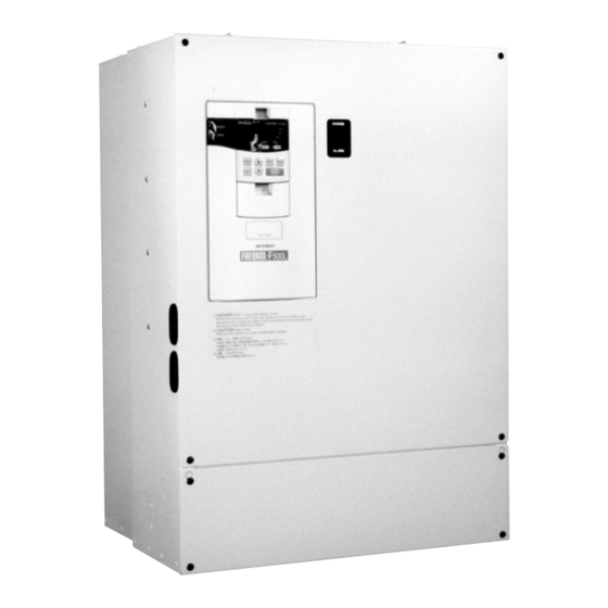
1.3 Structure OUTLINE 1.3.1 Appearance and structure (1) Front view (2) Without front cover POWER lamp ALARM lamp PU connector Operation panel (Provided with Modular jack type relay connector) (For use of RS-485 cable) Display window Modular jack type relay connector compartment Inboard option mounting position Accessory cover Control circuit terminal block... -
Page 15: Removal And Reinstallation Of The Front Cover
OUTLINE 1.3.2 Removal and reinstallation of the front cover ・Removal 1) Remove the installation screw for the main circuit terminal cover. 2) Remove the front cover mounting screws. ・Reinstallation 1) Fix the front cover with the mounting screws. 2) Fix the main circuit terminal cover with the installation screw. Note: 1.Confirm that the front cover and main circuit terminal cover have been securely installed. -
Page 16: Removal And Reinstallation Of The Operation Panel
OUTLINE 1.3.3 Removal and reinstallation of the operation panel To ensure safety, remove and reinstall the operation panel after switching power off. •Removal Hold down the top button of the operation panel and pull the operation panel toward you to remove Removal Reinstallation To reinstall, insert straight and mount securely. -
Page 17: Installation And Wiring
CHAPTER 2 INSTALLATION AND WIRING This chapter gives information on the basic "installation and wiring" of this product. Always read the instructions in this chapter before using the Chapter 1 equipment. 2.1 Installation ・・・・・・・・・・・・・・・・・・・・・・・・・・・・・・・・・・・ 6 Chapter 2 2.2 Wiring ・・・・・・・・・・・・・・・・・・・・・・・・・・・・・・・・・・・・・・・ 8 2.3 Other wiring ・・・・・・・・・・・・・・・・・・・・・・・・・・・・・・・・・・... -
Page 18: Installation
2.1 Installation INSTALLATION AND WIRING 2.1.1 Instructions for installation 1) Handle the unit carefully. The inverter uses plastic parts. Handle it gently to protect it from damage. Also, hold the unit with even strength and do not apply too much pressure to the front cover alone. 2) Install the inverter where it is not subjected to vibration. - Page 19 INSTALLATION AND WIRING 3) Note on ambient temperature 4) Clearances around the inverter Measurement 20cm Leave sufficient (7.87inches) position clearances above or more Cooling air and under the inverter to ensure (1.97inches) adeguate (1.97inches) ventilation. Measurement (1.97inches) position Cooling fan built in the inverter 20cm...
-
Page 20: Wiring
2.2 Wiring INSTALLATION AND WIRING 2.2.1 Terminal connection diagram Inverter FR-F500L Motor 3-phase AC power supply connector (Note 8) (RS-485) Ground Jumper (Note 3) (Note 1) DCL (Standard) 24VDC power output and extemal transistor common (Contact input common for source logic) (Note 8) Ground Forward rotation start... - Page 21 INSTALLATION AND WIRING 2.2.1 Terminal connection diagram of (-12P)
- Page 22 INSTALLATION AND WIRING 2.2.1 Terminal connection diagram...
- Page 23 INSTALLATION AND WIRING ( 1 ) Description of main circuit terminals Type Symbol Terminal Name Description R, S, T Connect to the commercial power supply. Keep these terminals unconnected when AC power input <L > using the high power factor converter (MT-HC). U, V, W Inverter output Connect a three-phase squirrel-cage motor.
- Page 24 INSTALLATION AND WIRING Type Symbol Terminal Name Description 10VDC, permissible load current When the frequency setting potentiometer is 10mA connected in the factory-set state, connect it to Frequency setting terminal 10. power supply 5VDC, permissible load current When it is connected to terminal 10E, change 10mA the input specifications of terminal 2.
-
Page 25: Wiring Of The Main Circuit
INSTALLATION AND WIRING 2.2.2 Wiring of the main circuit (1) Wiring instructions 1) Power must not be applied to the output terminals (U, V, W) of the inverter. Otherwise the inverter will be damaged. 2) After wiring, wire off-cuts must not be left in the inverter. Wire off-cuts can cause an alarm, failure or malfunction. - Page 26 INSTALLATION AND WIRING ( 2 ) Terminal block layout In the main circuit of the inverter, the terminals are arranged as shown below:...
- Page 27 INSTALLATION AND WIRING 2 2 2 2 2...
- Page 28 INSTALLATION AND WIRING (2) Terminal block layout (-12P) FR-F540L-75K-EC-12P FR-F540L-90K-EC-12P FR-F540L-110K-EC-12P FR-F540L-132K-EC-12P / 160K-EC-12P 13-A...
- Page 29 INSTALLATION AND WIRING FR-F540L-185K/-220K-EC-12P FR-F540L-280K-EC-12P FR-F540L-375K-EC-12P 13-B...
- Page 30 INSTALLATION AND WIRING (2) Terminal block layout of G-series FR-F540L-75K-(NA,EC,E1,CHG1) FR-F540L-90K / 110K-(NA,EC,E1,CHG1) FR-F540L-132K / 160K-(NA,EC,E1,CHG1) 13-C...
- Page 31 INSTALLATION AND WIRING FR-F540L-450K, 530K 13-D...
- Page 32 INSTALLATION AND WIRING ( 3 ) Cables, crimping terminals, etc. The following table lists the cables and crimping terminals used with the inputs (R, S, T) <L > and outputs (U, V, W) of the inverter and the torques for tightening the screws: Cables Terminal Tightening...
- Page 33 INSTALLATION AND WIRING ( 5 ) Connecting the control circuit to a power supply separately from the main circuit If the magnetic contactor (MC) in the inverter power supply is opened when the protective circuit is operated, the inverter control circuit power is lost and the alarm output signal cannot be kept on. To keep the alarm signal on, connect the power supply terminals R1 and S1 <L and L >...
-
Page 34: Wiring Of The Control Circuit
INSTALLATION AND WIRING 2.2.3 Wiring of the control circuit ( 1 ) Wiring instructions 1) Terminals SD, SE and 5 are common to the I/O signals and isolated from each other. These common terminals must not be connected to each other or earthed. 2) Use shielded or twisted cables for connection to the control circuit terminals and run them away from the main and power circuits (including the 200V relay sequence circuit). - Page 35 INSTALLATION AND WIRING ( 3 ) Changing the control logic The input signals are set to sink logic for the Japanese version, and to source logic for the EC version. To change the control logic, the connector on the back of the control circuit terminal block must be moved to the other position.
- Page 36 INSTALLATION AND WIRING 4) Sink logic type • In this logic, a signal switches on when a current flows out of the corresponding signal input terminal. Terminal SD is common to the contact input signals. Terminal SE is common to the open collector output signals.
- Page 37 INSTALLATION AND WIRING 5) Source logic type • In this logic, a signal switches on when a current flows into the corresponding signal input terminal. Terminal PC is common to the contact input signals. Terminal SE is common to the open collector output signals.
-
Page 38: Connection To The Pu Connector
INSTALLATION AND WIRING 2.2.4 Connection to the PU connector (1) When connecting the operation panel or parameter unit using a connection cable <Recommended cable connector> • Parameter unit connection cable (FR-CB2) (option) or the following connector and cable. • Connector: RJ45 connector Example: 5-554720-3, Nippon AMP •... - Page 39 2. Cable: Cable conforming to EIA568 (such as 10BASE-T cable) Example: SGLPEV 0.5mm×4P, Mitsubishi Cable Industries, Ltd. 3. *Commercially available converter examples: Model: FA-T-RS40 Converter Industrial System Division Mitsubishi Electric Engineering Co., Ltd. <Wiring method> 1) Wiring of one RS-485 computer and one inverter Inverter Computer Side Terminals...
-
Page 40: Connection Of Stand-Alone Option Units
INSTALLATION AND WIRING 2.2.5 Connection of stand-alone option units The inverter accepts a variety of stand-alone option units as required. Incorrect connection will cause inverter damage. Connect and operate the option unit carefully in accordance with the corresponding option unit manual. ( 1 ) Connection of the FR-BU brake unit (option) Connect the optional FR-BU brake unit as shown below to improve the braking capability during deceleration. - Page 41 INSTALLATION AND WIRING Note: 1. The wiring distance between the inverter, brake unit and discharge resistor should be used with in the cables which are attached on this unit (because of cable length). Resistor Unit must be installed in Air flow area. If twisted wires are used, the distance should be within 5m. 2.
- Page 42 INSTALLATION AND WIRING (4) Connection of the MT-RC power return converter (option) (For power coordination, always install the power factor-improving reactor (MT-RCL).) When connecting the MT-RC power return converter, connect the inverter terminals (P, N <+, ->) and MT-RC power return converter terminals as shown below so that their signals match with each other. After making sure that the wiring is correct, set "1"...
-
Page 43: Design Information
INSTALLATION AND WIRING 2.2.6 Design information 1) For commercial power supply-inverter switch-over operation, provide electrical and mechanical interlocks for MC1 and MC2 designed for commercial power supply-inverter switch-over. When there is a commercial power supply-inverter switch-over circuit as shown below, the inverter will be damaged by leakage current from the power supply due to arcs generated at the time of switch-over or chattering caused by a sequence error. -
Page 44: Other Wiring
2.3 Other wiring INSTALLATION AND WIRING 2.3.1 Inverter-driven 400V class motor In the PWM type inverter, a surge voltage attributable to wiring constants is generated at the motor terminals. Especially for a 400V class motor, the surge voltage may deteriorate the insulation. When the 400V class motor is driven by the inverter, consider the following measures: •... -
Page 45: Peripheral Devices
INSTALLATION AND WIRING 2.3.2 Peripheral devices (1) Selection of peripheral devices Check the capacity of the motor to be used with the inverter you purchased. Appropriate peripheral devices must be selected according to the capacity. Refer to the following list and prepare appropriate peripheral devices: For F520L, 200V class, For F540L, 400V class DRIVE Power Motor... -
Page 46: Instructions For Compliance With The Ul Standards
INSTALLATION AND WIRING 2.3.3 Instructions for compliance with the UL standards Since we obtained the approval of the UL and CSA Standards from the UL, the products conforming to the Standards carry the UL and CUL marks.) < For F540L 400V class DRIVE ; F540L is UL Listed > ( 1 ) Installation The below types of inverter have been approved as products for use in enclosure and approval tests were conducted under the following conditions. -
Page 47: Instructions For Compliance With The European Standards
INSTALLATION AND WIRING 2.3.4 Instructions for compliance with the European standards (The products conforming to the Low Voltage Directive carry the CE mark.) ( 1 ) EMC Directive 1) Our view of transistorized inverters for the EMC Directive A transistorized inverter does not function independently. It is a component designed for installation in a control box and for use with the other equipment to control the equipment/device. -
Page 48: Earthing
INSTALLATION AND WIRING 2.3.5 Earthing (1) Earthing and Earth Leakage Current (a) Purpose of Earthing Electrical equipment usually has an Earthing Terminal, this must be connected to earth before using equipment. For protection, electric circuits are normally housed inside an insulated case. However it is impossible to manufacture insulating materials that prevent all current from leaking across them, therefore it is the function of the earth (safety earth) to prevent electric shocks when touching the case. -
Page 49: Power Harmonics
INSTALLATION AND WIRING 2.3.6 Power harmonics Power harmonics may be generated from the converter section of the inverter, affecting power supply equipment, power capacitors, etc. Power harmonics are different in generation source, frequency and transmission path from radio frequency (RF) noise and leakage currents. Take the following measures. •... -
Page 50: Japanese Harmonic Suppression Guidelines
? Harmomic suppression technique is required. Not more than maximum value Harmomic suppression technique is not required. Table 2 Conversion Factors for FR-F500 Series Class Circuit Type Conversion Factor Ki With reactor (DC side) K33 = 1.8... - Page 51 INSTALLATION AND WIRING 1) Calculation of equivalent capacity (P0) of harmonic generating equipment The "equivalent capacity" is the capacity of a 6-pulse converter converted from the capacity of consumer’s harmonic generating equipment and is calculated with the following equation. If the sum of equivalent capacities is higher than the limit in Table 3, harmonics must be calculated with the following procedure: P0 = Σ...
-
Page 52: Inverter-Generated Noises And Reduction Techniques
INSTALLATION AND WIRING 2.3.8 Inverter-generated noises and reduction techniques Some noises enter the inverter causing it to misoperate and others are radiated by the inverter causing misoperation of peripheral devices. Though the inverter is designed to be insusceptible to noise, it handles low-level signals, so it requires the following basic measures to be taken. - Page 53 INSTALLATION AND WIRING Noise Path Measures When devices which handle low-level signals and are susceptible to misoperation due to noise (such as instruments, receivers and sensors) are installed near the inverter and their signal cables are contained in the same panel as the inverter or are run near the inverter, the devices may be effected by air-propagated noises and the following measures must be taken: (1) Install easily affected devices as far away as possible from the inverter.
-
Page 54: Leakage Currents And Countermeasures
INSTALLATION AND WIRING Example of measures against noises Reduce carrier frequency. Control box Install filter (FR-BLF) to Install filter (FR-BLF) to Install filter (FR-BLF) to Install filter (FR-BLF,FR- inverter input side. inverter output side. inverter input side. Install filter (FR-BLF,FR-BSF01) BSF01) to inverter input side. -
Page 55: Inverter-Driven 400V Class Motor
INSTALLATION AND WIRING ( 2 ) Line-to-line leakage currents Harmonics of leakage currents flowing in static capacities between the inverter output cables might operate the external thermal relay unnecessarily. Thermal relay Motor Power Inverter supply Line static capacitances Line-to-Line Leakage Current Path Countermeasures •... -
Page 56: Operation
CHAPTER 3 OPERATION This chapter provides the basic "operation" for use of this product. Always read this chapter before using the equipment. Chapter 1 3.1 Pre-Operation Information ・・・・・・・・・・・・・・・・・・・・・・ 38 3.2 Opreration Panel・・・・・・・・・・・・・・・・・・・・・・・・・・・・・・ 41 Chapter 2 3.3 Parameter Checking and Setting ・・・・・・・・・・・・・・・・ 47 3.4 Operation ・・・・・・・・・・・・・・・・・・・・・・・・・・・・・・・・・・・・... -
Page 57: Pre-Operation Information
3.1 Pre-Operation Information OPERATION 3.1.1 Devices and parts to be prepared for operation The inverter can be operated in any of the "external operation mode", "PU operation mode", "combined operation mode" and "communication operation mode". Prepare required instruments and parts according to the operation mode. - Page 58 Communication operation can be performed by connecting a personal computer and the PU connector with the RS-485 communication cable. The inverter setup software (FR-SW0-SETUP-WE (or –WJ for Japanese Version)) is available as a startup support software package for the FR-F500. Preparation • Connection cable......Connector...
-
Page 59: Power On
OPERATION 3.1.2 Power on Before switching power on, check the following: • • • • Installation check Make sure that the inverter is installed correctly in a proper location. (Refer to page 6.) • Wiring check Make sure that the main and control circuits are wired correctly. Make sure that the options and peripheral devices are selected and connected correctly. -
Page 60: Operation Panel
3.2 Operation Panel OPERATION With the operation panel (FR-DU04), you can set the running frequency, monitor the operation command display, set parameters, display an error, and copy parameters. 3.2.1 Names and functions of the operation panel (FR-DU04) FR-DU04 Unit indication CONTROL PANEL Hz (frequency) Display... -
Page 61: Monitor Display Changed By Pressing The [Mode] Key
OPERATION 3.2.2 Monitor display changed by pressing the [MODE] key Monitoring mode Frequency setting mode Parameter setting mode Operation mode Help mode (Note) FR-DU04 FR-DU04 FR-DU04 FR-DU04 FR-DU04 CONTROL PANEL CONTROL PANEL CONTROL PANEL CONTROL PANEL CONTROL PANEL MODE MODE MODE MODE MODE... -
Page 62: Parameter Setting Mode
OPERATION 3.2.5 Parameter setting mode • A parameter value may either be set by updating its parameter number or setting the value digit-by-digit using the [UP/DOWN] key. • To write the setting, change it and press the [SET] key 1.5 seconds. Set "1"... -
Page 63: Help Mode
OPERATION 3.2.7 Help mode Alarm history Alarm history Parameter All clear User clear Software version FR-DU04 clear read CONTROL PANEL clear MODE To 3.2.3 Monitoring mode • Alarm history Four past alarms can be displayed with the [UP/DOWN] key. ("." is appended to the most recent alarm.) (When no alarm exists, E._ _0 is displayed.) Most recent alarm FR-DU04... - Page 64 OPERATION • Parameter clear Initialises the parameter values to the factory settings. The calibration values are not initialized. (Parameter values are not cleared by setting "1" in Pr. 77 "parameter write disable selection.) Flicker FR-DU04 FR-DU04 FR-DU04 FR-DU04 CONTROL PANEL CONTROL PANEL CONTROL PANEL CONTROL PANEL...
-
Page 65: Copy Mode
"verify error (E.rE3)" flickers. To ignore this display and continue verify, press the [SET] key. 5. When the copy destination inverter is not the FR-F500 series, "model error (E.rE4)" is displayed. Reference: It is recommended to read the parameter values after completion of parameter setting. -
Page 66: Parameter Checking And Setting
3.3 Parameter Checking and Setting OPERATION The inverter is designed to perform simple variable-speed operation with the factory settings of the parameters. Set the necessary parameters according to the load and operation specifications. Use the operation panel (FR-DU04) to set, charge and confirm the parameter values. For full information on the parameters, refer to "CHAPTER 4 PARAMETERS"... - Page 67 OPERATION Parameter Name Application Number Used to cause the inverter to automatically set the appropriate parameters Intelligent mode selection and perform operation. Used to select the alarm whose occurrence will cause the inverter to reset and Retry selection retry automatically. Stall prevention operation reduction starting frequency Number of retries at alarm...
-
Page 68: Main Parameter Settings
OPERATION 3.3.2 Main parameter settings The main parameter settings are given below. For more information, refer to "CHAPTER 4 PARAMETERS". (1) Setting of maximum frequency ( Pr. 1 "maximum frequency" ) Set this parameter to define the upper limit of the output frequency. You can limit the maximum frequency within the range of the frequency set in Pr. - Page 69 OPERATION (5) Selection of load pattern (Pr. 14 "load pattern selection") Used to select the output characteristic (V/F characteristic) according to the application and load characteristics. Application Setting For constant torque load (e.g. conveyor, cart) For variable torque load (fan, pump) (Factory setting) Note: When the RT terminal is ON, the second control functions (second acceleration/deceleration, second torque boost, second base frequency) are selected.
-
Page 70: Operation
3.4 Operation OPERATION 3.4.1 Pre-operation checks Before starting operation, check the following: • Safety Perform test operation after making sure that safety is ensured if the machine should become out of control. • Machine Make sure that the machine is free of damage. •... -
Page 71: External Operation Mode (Operation Using External Input Signals)
OPERATION 3.4.2 External operation mode (Operation using external input signals) ( 1 ) Operation at 60Hz Step Description Image Power-on → Operation mode check Switch power on and make sure that the operation command indication "EXT" is lit. (If it is not lit, switch to the external operation mode. For operation mode changing, refer to page 43.) FR-DU04 CONTROL PANEL... -
Page 72: Pu Operation Mode (Operation Using The Operation Panel (Fr-Du04))
OPERATION 3.4.3 PU operation mode (Operation using the operation panel (FR-DU04)) ( 1 ) Operation at 60Hz While the motor is running, repeat the following steps 2 and 3 to vary the speed: Step Description Image Power-on → Operation mode check Switch power on and make sure that the operation command indication "PU"... -
Page 73: Combined Operation Mode (Operation Using The External Input Signals And Pu)
OPERATION 3.4.4 Combined operation mode (Operation using the external input signals and PU) When entering the start signal from outside the inverter and setting the running frequency from the PU (Pr. 79 = 3) The external frequency setting signals and the PU's FWD, REV and STOP keys are not accepted. (Note) Step Description Image... -
Page 74: Parameters
CHAPTER 4 PARAMETERS This chapter explains the "parameters" of this product. Always read the instructions before using the equipment. Chapter 1 4.1 Parameter List ・・・・・・・・・・・・・・・・・・・・・・・・・・・・・・・・ 55 4.2 Parameter Function Details・・・・・・・・・・・・・・・・・・・・・ 61 Chapter 2 Note: By making parameter settings, you can change the functions of contact input terminals RL, RM, RH, RT, AU, JOG, CS and open collector output terminals RUN, SU, IPF, OL, FU. -
Page 75: Parameter List
4.1 Parameter List PARAMETERS 4.1.1 Parameter list All parameters available when the Pr. 160 "user group read selection" value is "0" are indicated below. The parameters available when the Pr. 160 value is "9999" (Simple mode parameter) are marked in the Parameter Number column with a circle ( ). - Page 76 PARAMETERS Cust- Factory Minimum Refer Func- Parameter omer Setting Name Setting Range Setting [EC,CH Version] tion Number Set- Increments Page: 〈 〈 〈 〈 EC Version only〉 〉 〉 〉 ting Up-to-frequency sensitivity 0 to 100% 0.1% Output frequency detection 0 to 120Hz 0.01Hz Output frequency detection for reverse...
- Page 77 PARAMETERS Cust- Factory Minimum Refer Func- Parameter omer Setting Name Setting Range Setting [EC,CH Version] tion Number Set- Increments Page: 〈 〈 〈 〈 EC Version only〉 〉 〉 〉 ting V/F4 (fourth frequency voltage) 0 to 1000V 0.1V V/F5 (fifth frequency) 0 to 120Hz, 9999 0.01Hz 9999...
- Page 78 PARAMETERS Cust- Factory Minimum Refer Func- Parameter omer Setting Name Setting Range Setting tion Number [EC,CH Version] Set- Increments Page: 〈 〈 〈 〈 EC Version only〉 〉 〉 〉 ting Zero current detection level 0 to 200.0% 0.1% 5.0% Zero current detection period 0 to 1 s 0.01 s...
- Page 79 PARAMETERS Cust- Factory Minimum Refer Func- Parameter omer Setting Name Setting Range Setting [EC,CH Version] tion Number Set- Increments Page: 〈 〈 〈 〈 EC Version only〉 〉 〉 〉 ting Soft-PWM setting 0, 1 Cooling fan operation selection 0, 1 Output phase failure protection selection 0, 1 Override bias...
-
Page 80: List Of Parameters Classified By Purposes Of Use
PARAMETERS 4.1.2 List of Parameters Classified by Purposes of Use Set the parameters according to the operating conditions. The following list indicates purposes of use and parameters. Parameter Numbers Purpose of Use Parameter numbers which must be set Switch-over to optimum excitation control operation Pr. -
Page 81: Parameter Function Details
4.2 Parameter Function Details PARAMETERS 4.2.1 Torque boost (Pr. 0, Pr. 46) Related parameters Pr. 0 "torque boost" Pr. 3 "base frequency" Pr. 46 "second torque boost" Pr. 19 "base frequency voltage" Pr. 71 "applied motor" Pr. 180 to Pr. 186 (input terminal function selection) You can compensate for a voltage drop in the low frequency range to improve motor torque reduction in the low speed range. -
Page 82: Output Frequency Range (Pr. 1, Pr. 2)
PARAMETERS 4.2.2 Output frequency range (Pr. 1, Pr. 2) Pr. 1 "maximum frequency" Related parameters Pr. 13 "starting frequency" Pr. 2 "minimum frequency" Pr. 903 "frequency setting voltage gain" Pr. 905 "frequency setting current gain" Used to clamp the upper and lower limits of the output frequency. Can be used to set the upper and lower limits of motor speed. -
Page 83: Base Frequency, Base Frequency Voltage (Pr. 3, Pr. 19, Pr. 47)
PARAMETERS 4.2.3 Base frequency, base frequency voltage (Pr. 3, Pr. 19, Pr. 47) Pr. 3 "base frequency" Related parameters Pr. 71 "applied motor" Pr. 19 "base frequency voltage" Pr. 180 to Pr. 186 (input terminal function selection) Pr. 47 "second V/F (base frequency) Used to adjust the inverter outputs (voltage, frequency) to the motor rating. -
Page 84: Multi-Speed Operation (Pr. 4 To Pr. 6, Pr. 24 To Pr.27)
PARAMETERS 4.2.4 Multi-speed operation (Pr. 4 to Pr. 6, Pr. 24 to Pr.27) Pr. 4 "3-speed setting (high speed)" Related parameters Pr. 1 "maximum frequency" Pr. 5 "3-speed setting (middle speed)" Pr. 2 "minimum frequency" Pr. 15 "jog frequency" Pr. 6 "3-speed setting (low speed)" Pr. -
Page 85: Acceleration/Deceleration Time (Pr. 7, Pr. 8, Pr. 20, Pr. 21, Pr. 44, Pr. 45)
PARAMETERS 4.2.5 Acceleration/deceleration time (Pr. 7, Pr. 8, Pr. 20, Pr. 21, Pr. 44, Pr. 45) Pr. 7 "acceleration time" Related parameters Pr. 3 "base frequency" Pr. 8 "deceleration time" Pr. 29 "acceleration/deceleration pattern" Pr. 20 "acceleration/deceleration reference frequency" Pr. 21 "acceleration/deceleration time increments" Pr. -
Page 86: Electronic Overcurrent Protection (Pr. 9)
PARAMETERS Note: 1. In S-shaped acceleration/deceleration pattern A (refer to page 74), the set time is a period required to reach the base frequency set in Pr. 3. • Acceleration/deceleration time calculation expression when the set frequency is the base frequency or higher ×... -
Page 87: Dc Dynamic Brake (Pr. 10 To Pr. 12)
PARAMETERS 4.2.7 DC dynamic brake (Pr. 10 to Pr. 12) Pr. 10 "DC dynamic brake operation frequency" Related parameters Pr. 13 "starting frequency" Pr. 11 "DC dynamic brake operation time" Pr. 71 "applied motor" Pr. 12 "DC dynamic brake voltage" By setting the stopping DC dynamic brake voltage (torque), operation time and operation starting frequency, the stopping accuracy of positioning operation, etc. -
Page 88: Starting Frequency (Pr. 13)
PARAMETERS 4.2.8 Starting frequency (Pr. 13) Related parameters Pr. 13 "starting frequency" Pr. 2 "minimum frequency" You can set the starting frequency between 0 and 60Hz. Set the starting frequency at which the start signal is switched on. Parameter <Setting> Factory Setting Setting Range Number... -
Page 89: Load Pattern Selection (Pr. 14)
PARAMETERS 4.2.9 Load pattern selection (Pr. 14) Related parameters Pr. 14 "load pattern selection" Pr. 0 "torque boost" Pr. 60 " intelligent mode selection" Pr. 180 to Pr. 186 (input terminal function selection) You can select the optimum output characteristic (V/F characteristic) for the application and load characteristics. -
Page 90: Jog Operation (Pr. 15, Pr. 16)
PARAMETERS 4.2.10 Jog operation (Pr. 15, Pr. 16) Pr. 15 "jog frequency" Related parameters Pr. 20 "acceleration/deceleration Pr. 16 "jog acceleration/deceleration time" reference frequency" Pr. 21 "acceleration/deceleration time increments" Pr. 79 "operation mode selection" Pr. 180 to Pr. 186 (input terminal function selection) In the external operation mode, jog operation can be started and stopped with the start signal (STF, STR) after selection of the jog mode (JOG signal ON). -
Page 91: Mrs Input Selection (Pr. 17)
PARAMETERS 4.2.11 MRS input selection (Pr. 17) Pr. 17 "MRS input selection" Used to select the logic of the MRS signal. When the MRS signal switches on, the inverter shuts off the output. Parameter Factory Setting Range Number Setting 0, 2 <Setting>... -
Page 92: Stall Prevention (Pr. 22, Pr. 23, Pr. 66, Pr. 148, Pr. 149, Pr. 154)
PARAMETERS 4.2.12 Stall prevention (Pr. 22, Pr. 23, Pr. 66, Pr. 148, Pr. 149, Pr. 154) Pr. 22 "stall prevention operation level" Related parameters Pr. 9 "electronic thermal O/L relay" Pr. 23 "stall prevention operation level at double Pr. 48 "second stall prevention operation current"... -
Page 93: Multi-Speed Input Compensation (Pr. 28)
PARAMETERS <Setting> • In Pr. 22, set the stall prevention operation level. Normally set it to 120% (factory setting). Set "0" in Pr. 22 to disable the stall prevention operation. • To reduce the stall prevention operation level in the high-frequency range, set the reduction starting frequency in Pr. -
Page 94: Acceleration/Deceleration Pattern (Pr. 29, Pr.140 To Pr.143)
PARAMETERS 4.2.14 Acceleration/deceleration pattern (Pr. 29, Pr.140 to Pr.143) Pr. 29 "acceleration/deceleration pattern" Related parameters Pr. 3 "base frequency" Pr. 140 "backlash acceleration stopping frequency" Pr. 7 "acceleration time" Pr. 8 "deceleration time" Pr. 141 "backlash acceleration stopping time" Pr. 20 "acceleration/deceleration reference frequency"... -
Page 95: Regenerative Brake Duty (Pr.30, Pr.70)
PARAMETERS 4.2.15 Regenerative brake duty (Pr.30, Pr.70) Pr. 30 "regenerative function selection" Related parameters Pr. 180 "RL terminal function selection" Pr.70 "special regenerative brake duty" Pr. 181 "RM terminal function selection" Pr. 182 "RH terminal function selection" Pr. 183 "RT terminal function selection" Pr. -
Page 96: Frequency Jump (Pr. 31 To Pr. 36)
PARAMETERS 4.2.16 Frequency jump (Pr. 31 to Pr. 36) Pr. 31 "frequency jump 1A" Pr. 32 "frequency jump 1B" Pr. 33 "frequency jump 2A" Pr. 34 "frequency jump 2B" Pr. 35 "frequency jump 3A" Pr. 36 "frequency jump 3B" When it is desired to avoid resonance attributable to the natural frequency of a mechanical system, these parameters allow resonant frequencies to be jumped. -
Page 97: Speed Display (Pr. 37, Pr. 144)
PARAMETERS 4.2.17 Speed display (Pr. 37, Pr. 144) Pr. 37 "speed display" Related parameters Pr. 52 "PU main display data selection" Pr. 144 "speed setting switch-over" Pr. 53 "PU level display data selection" The units of the running speed monitor display of the PU (FR-DU04/FR-PU04), the running speed setting in the PU operation mode, and the parameter setting used for frequency setting can be changed from the frequency to the motor speed or machine speed. -
Page 98: Automatic Torque Boost (Pr. 38, Pr. 39)
PARAMETERS 4.2.18 Automatic torque boost (Pr. 38, Pr. 39) Pr. 38 "automatic torque boost" Pr. 39 "automatic torque boost operation starting current" Used to detect the load current to control the output voltage (torque) of the inverter automatically. Parameter Number Factory Setting Setting Range Setting Capacity... -
Page 99: Output Frequency Detection (Pr. 42, Pr. 43, Pr. 50)
PARAMETERS 4.2.20 Output frequency detection (Pr. 42, Pr. 43, Pr. 50) Pr. 42 "output frequency detection" Pr. 43 "output frequency detection for reverse rotation" Pr. 50 "second output frequency detection" The output frequency signal (FU, FU2) is output when the output frequency reaches or exceeds the setting. This function can be used for electromagnetic brake operation, open signal, etc. -
Page 100: Second Stall Prevention (Pr. 48, Pr. 49)
PARAMETERS 4.2.21 Second stall prevention (Pr. 48, Pr. 49) Pr. 48 "second stall prevention operation current" Related parameters Pr. 22 "stall prevention operation level" Pr. 49 "second stall prevention operation Pr. 23 "stall prevention operation level frequency" at double speed" Pr. -
Page 101: Monitor Display / Fm, Am Terminal Function Selection (Pr. 52 To Pr. 54, Pr. 158)
PARAMETERS 4.2.22 Monitor display / FM, AM terminal function selection (Pr. 52 to Pr. 54, Pr. 158) Pr. 52 "DU/PU main display screen data selection" Related parameters Pr. 37 "speed display" Pr. 53 "PU level display data selection" Pr. 55 "frequency monitoring reference" Pr. - Page 102 PARAMETERS When 100 is set in Pr. 52, the monitored values during stop and during operation differ as indicated below: (The LED on the left of Hz flickers during a stop and is lit during running.) Pr. 52 During During stop During operation operation/during stop Output frequency...
-
Page 103: Monitoring Reference (Pr. 55, Pr. 56)
PARAMETERS 4.2.23 Monitoring reference (Pr. 55, Pr. 56) Pr. 55 "frequency monitoring reference" Related parameters Pr. 37 "speed display" Pr. 56 "current monitoring reference" Pr. 53 "PU level display data selection" Pr. 54 "FM terminal function selection" Pr. 158 "AM terminal function selection" Pr. -
Page 104: Automatic Restart After Instantaneous Power Failure (Pr. 57, Pr. 58, Pr. 162 To Pr. 165)
PARAMETERS 4.2.24 Automatic restart after instantaneous power failure (Pr. 57, Pr. 58, Pr. 162 to Pr. 165) Pr. 57 "coasting time for automatic restart after instantaneous power failure/commercial power supply-inverter switch-over" Pr. 58 "cushion time for automatic restart after instantaneous power failure/commercial power supply-inverter switch-over"... - Page 105 PARAMETERS <Setting> Refer to the figures in the previous page and following table, and set the parameters: Parameter Setting Description Number Frequency search made Frequency search is made after detection of an instantaneous power failure. No frequency search Independently of the motor coasting speed, the output voltage is gradually increased with the frequency kept as preset.
-
Page 106: Remote Setting Function Selection (Pr. 59)
PARAMETERS 4.2.25 Remote setting function selection (Pr. 59) Pr. 59 "remote setting function selection" Related parameters Pr. 1 "maximum frequency" Pr. 7 "acceleration time" Pr. 8 "deceleration time" Pr. 28 "multi-speed input compensation" Pr. 44 "second acceleration/deceleration time" Pr. 45 "second deceleration time" If the operator panel is located away from the control box, you can use contact signals to perform continuous variable-speed operation, without using analog signals. - Page 107 PARAMETERS Note: 1. The frequency can be varied by RH (acceleration) and RM (deceleration) between 0 and 120Hz. 2. When the acceleration or deceleration signal switches on, the set frequency varies according to the slope set in Pr. 44 or Pr. 45. The output frequency acceleration/deceleration times are as set in Pr.
-
Page 108: Intelligent Mode Selection (Pr. 60)
PARAMETERS 4.2.26 Intelligent mode selection (Pr. 60) Pr. 60 "intelligent mode selection" Related parameters Pr. 0 "torque boost" Pr. 7 "acceleration time" Pr. 8 "deceleration time" Pr. 13 "starting frequency" Pr. 19 "base frequency voltage" The inverter automatically sets appropriate parameters for operation. •... -
Page 109: Acceleration/Deceleration Reference Current/Lift Mode Starting Frequency (Pr. 61 To Pr. 63)
PARAMETERS 4.2.27 Acceleration/deceleration reference current/lift mode starting frequency (Pr. 61 to Pr. 63) Pr. 61 "reference current" Related parameter Pr. 60 "intelligent mode selection" Pr. 62 "reference current for acceleration" Pr. 63 "reference current for deceleration" Set these parameters to improve performance in the intelligent mode. Parameter Factory Setting Range... -
Page 110: Retry Function (Pr. 65, Pr. 67 To Pr. 69)
PARAMETERS 4.2.28 Retry function (Pr. 65, Pr. 67 to Pr. 69) Pr. 65 "retry selection" Pr. 67 "number of retries at alarm occurrence" Pr. 68 "retry waiting time" Pr. 69 "retry count display erasure" When an alarm occurs, the retry function causes the inverter to automatically reset itself to make a restart and continue operation. - Page 111 PARAMETERS • Use Pr. 67 to set the number of retries at alarm occurrence. Pr. 67 Setting Number of Retries Alarm Signal Output Retry is not made. 1 to 10 1 to 10 times Not output. 101 to 110 1 to 10 times Output.
-
Page 112: Applied Motor (Pr. 71)
PARAMETERS 4.2.29 Applied motor (Pr. 71) Pr. 71 "applied motor" Related parameters Pr. 0 "torque boost" Pr. 12 "DC dynamic brake voltage" Pr. 19 "base frequency voltage" Pr. 60 "intelligent mode" Pr. 100 to Pr. 109 " Set the motor used. V/F frequency/voltage"... -
Page 113: Pwm Carrier Frequency (Pr. 72, Pr. 240)
PARAMETERS 4.2.30 PWM carrier frequency (Pr. 72, Pr. 240) Pr. 72 "PWM frequency selection" Pr. 240 "Soft-PWM setting" You can change the motor tone. By parameter setting, you can select Soft-PWM control which changes the motor tone. Soft-PWM control changes motor noise from a metallic tone into an unoffending complex tone. Parameter Factory Setting Range... -
Page 114: Voltage Input (Pr. 73)
PARAMETERS 4.2.31 Voltage input (Pr. 73) Pr. 73 "0-5V/0-10V selection" Related parameters Pr. 22 "stall prevention operation level" Pr. 903 "frequency setting voltage bias" Pr. 905 "frequency setting current gain" You can select the analog input terminal specifications, the override function and the function to switch between forward and reverse rotation depending on the input signal polarity. -
Page 115: Input Filter Time Constant (Pr. 74)
PARAMETERS 4.2.32 Input filter time constant (Pr. 74) Pr. 74 "filter time constant" You can set the input section's internal filter constant to an external voltage or current frequency setting signal. Effective for eliminating noise in the frequency setting circuit. Increase the filter time constant if steady operation cannot be performed due to noise. - Page 116 PARAMETERS How to make a restart after a stop made by the [STOP] key from the PU during external operation (1) Operation panel (FR-DU04) 1) After completion of deceleration to a stop, switch off the STF or STR signal. 2) Press the [MODE] key two times* to call the indication.
-
Page 117: Alarm Code Output Selection (Pr. 76)
PARAMETERS 4.2.34 Alarm code output selection (Pr. 76) Pr. 76 "alarm code output selection" Related parameters Pr. 79 "operation mode selection" Pr. 190 to Pr. 195 (multi-function outputs) When an alarm occurs, its code can be output as a 4-bit digital signal from the open collector output terminals. When programmed operation has been selected, this parameter also serves to output a group operation signal. -
Page 118: Parameter Write Inhibit Selection (Pr. 77)
PARAMETERS 4.2.35 Parameter write inhibit selection (Pr. 77) Pr. 77 "parameter write disable selection" You can select between write-enable and disable for parameters. This function is used to prevent parameter values from being rewritten by accident. Parameter Factory Setting Range Number Setting 0, 1, 2... -
Page 119: Reverse Rotation Prevention Selection (Pr. 78)
PARAMETERS 4.2.36 Reverse rotation prevention selection (Pr. 78) Pr. 78 "reverse rotation prevention selection" This function can prevent any reverse rotation fault resulting from the misoperation of the start signal. Used for a machine which runs only in one direction, e.g. fan, pump. (The setting of this function is valid for the PU, external and communication operations.) Parameter Factory... -
Page 120: Operation Mode Selection (Pr. 79)
PARAMETERS 4.2.37 Operation mode selection (Pr. 79) Related parameters Pr. 79 "operation mode selection" Pr. 15 "jog frequency" Pr. 4 to Pr. 6, Pr. 24 to 27 "multi-speed operation" Pr. 76 "alarm code output selection" Pr. 180 to Pr. 186 (input terminal function selection) Used to select the operation mode of the inverter. - Page 121 PARAMETERS ( 1 ) Switch-over mode You can select between PU operation, external operation and computer link operation (when FR-A5NR option is used). Operation Mode Switching Switching Operation/Operating Status 1) Select the PU operation mode. • Rotation direction is the same as that of external operation. External operation to PU operation •...
- Page 122 PARAMETERS <Function/operation changed by switching on-off the X12 (MRS) signal> Operating Condition Switching Operation X12 (MRS) to PU Mode Operating Status Parameter Write Operation Signal Operation Status (Note 4) mode Mode ON → OFF Allowed → disallowed During stop During stop Disallowed (Note 3) If external operation...
-
Page 123: V/F Control Frequency (Voltage) (Pr. 100 To Pr. 109)
PARAMETERS 4.2.38 V/F control frequency (voltage) (Pr. 100 to Pr. 109) Pr. 100 "V/F1 (first frequency)" Related parameters Pr. 19 "base frequency voltage" Pr. 101 "V/F1 (first frequency voltage)" Pr. 47 "second V/F (base frequency)" Pr. 60 "intelligent mode selection" Pr. -
Page 124: Computer Link Operation (Pr. 117 To Pr. 124)
PARAMETERS (2) Set the desired frequencies and voltages in Pr. 100 to Pr. 109. • The setting must satisfy the following relationship: F1≠F2≠F3≠F4≠F5≠Pr. 19 "base frequency". If the set frequencies are the same, a write error occurs. If any frequency setting is "9999", its point is ignored. Note: 1. - Page 125 PARAMETERS For the data codes of the parameters, refer to the data code list in the appendices. Parameter Factory Setting Range Number Setting 0 to 31 48, 96, 192 Data length 8 0, 1 Data length 7 10, 11 0, 1, 2 0 to 10, 9999 0 <9999>...
- Page 126 PARAMETERS <Computer programming> ( 1 ) Communication protocol Data communication between the computer and inverter is performed using the following procedure: Data read Computer ↓ (Data flow) Inverter Time Inverter ↓ (Data flow) Data write Computer *1. If a data error is detected and a retry must be made, execute retry operation from the user program. The inverter comes to an alarm stop if the number of consecutive retries exceeds the parameter setting.
- Page 127 PARAMETERS Note: 1. The inverter station numbers may be set between H00 and H1F (stations 0 and 31) in hexadecimal. 2. *3 indicates the control code. 3. *4 indicates the CR or LF code. When data is transmitted from the computer to the inverter, codes CR (carriage return) and LF (line feed) are automatically set at the end of a data group on some computers.
- Page 128 PARAMETERS 5) Waiting time Specify the waiting time between the receipt of data at the inverter from the computer and the transmission of reply data. Set the waiting time in accordance with the response time of the computer between 0 and 150ms in 10ms increments (e.g.
- Page 129 PARAMETERS 7) Error code If any error is found in the data received by the inverter, its definition is sent back to the computer together with the NAK code. (Refer to page109.) Note: 1. When the data from the computer has an error, the inverter will not accept that data. 2.
- Page 130 PARAMETERS Instructions for the program (1) If the data from the computer is in error, the inverter will not accept that data. Hence, always insert a data- error retry program in the user program. (2) Since any data communication, such as operation command or monitoring, is always requested by the computer, the inverter will not return data without the computer's request.
- Page 131 PARAMETERS <Setting items and set data> After completion of parameter setting, set the instruction codes and data and start communication from the computer to allow various types of operation control and monitoring. Instruction Number of Item Description Code Data Digits H0000: Communication option operation Read H0001: External operation...
- Page 132 PARAMETERS Number Instruction Item Description of Data Code Digits H00 to HFF: Run command b1: Forward rotation (STF) b2: Reverse rotation (STR) (For example 1) Run command 2 digits [Example 1] H02 ... Forward rotation [Example 2] H00 ... Stop H00 to HFF: Inverter status monitor b0: Inverter running (RUN) * b1: Forward rotation...
- Page 133 PARAMETERS <Error Code List> The corresponding error code in the following list is displayed if an error is detected in any communication request data form the computer. Error Item Definition Inverter Operation Code The number of errors consecutively detected in communication request Computer NAK error data from the computer is greater than allowed number of retry times.
- Page 134 PARAMETERS ( 5 ) Communication specifications for RS-485 communication Operation Mode Communication Operation Location Item External Computer Link Operation Operation from PU Operation (inboard option used) Connector Run command (start) Enable Disable Disable Enable Running frequency setting Enable (Combined Disable operation mode) Computer user program via Monitoring...
-
Page 135: Pid Control (Pr. 128 To Pr. 134)
PARAMETERS 4.2.40 PID control (Pr. 128 to Pr. 134) Pr. 128 "PID action selection" Related parameters Pr. 73 "0-5V/0-10V selection" Pr. 129 "PID proportional band" Pr. 79 "operation mode selection" Pr. 180 to Pr. 186 Pr. 130 "PID integral time" (input terminal assignment) Pr. - Page 136 PARAMETERS 2) PD action A combination of proportional control action (P) and differential control action (D) for providing a manipulated variable in response to deviation speed to improve the transient characteristic. Set point [Operation example for proportional changes of process value] Deviation Process...
- Page 137 PARAMETERS ( 3 ) Wiring example • Sink logic • Pr. 183 = 14 • Pr. 192 = 16 • Pr. 193 = 14 • Pr. 194 = 15 Inverter Motor Pump R 〈L 〉 S 〈L 〉 Power supply T 〈L 〉...
- Page 138 PARAMETERS ( 4 ) I/O signals Signal Terminal Used Function Description Remarks Depending on PID control Set any of "10, 11, 20 Switch on X14 to select PID control. Pr. 180 to Pr. 186 selection and 21" in Pr. 128. Set point input Enter the set point for PID control.
- Page 139 PARAMETERS ( 5 ) Parameter setting Parameter Setting Name Description Number For heating, pressure control, PID reverse Deviation value etc. action signal input PID forward For cooling, etc. (terminal 1) PID action action selection For heating, pressure control, PID reverse etc.
- Page 140 PARAMETERS ( 7 ) Calibration example (A detector of 4mA at 0°C and 20mA at 50°C is used to adjust the room temperature to 25°C under PID control. The set point is given to across inverter terminals 2-5 (0-5V).) START Determine the set point.
- Page 141 PARAMETERS <Set point input calibration> 1. Apply the input voltage of 0% set point setting (e.g. 0V) to across terminals 2-5. 2. Make calibration using Pr. 902. At this time, enter the frequency (e.g. 0Hz) which should be output by the inverter at the deviation of 0%.
-
Page 142: Commercial Power Supply-Inverter Switch-Over Function (Pr. 135 To Pr. 139)
PARAMETERS 4.2.41 Commercial power supply-inverter switch-over function (Pr. 135 to Pr. 139) Pr. 135 "commercial power supply-inverter Related parameters switch-over sequence output terminal selection" Pr. 11 "DC dynamic brake operation time" Pr. 136 "MC switch-over interlock time" Pr. 17 "MRS input selection" Pr. - Page 143 PARAMETERS ( 1 ) Wiring example Sink logic, Pr. 185 = 7, Pr. 186 = 6, Pr. 192 = 17, Pr. 193 = 18, Pr. 194 = 19 × External Inverter thermal relay R 〈L 〉 S 〈L 〉 T 〈L 〉...
- Page 144 PARAMETERS • Roles of the magnetic contactors (MC1, MC2, MC3) Magnetic Place of Installation Role Contactor Normally shorted with the following exception: Between power supply and inverter Opened only when an inverter fault occurs (shorted again by resetting) Shorted for commercial power supply operation, opened for inverter operation Between power supply and motor Shorted when an inverter fault occurs (selected with parameter, except...
- Page 145 PARAMETERS ( 2 ) Parameter setting Parameter Name Setting Description Number Sequence output is not provided. (Pr. 136, Pr. 137, Pr. 138 and Pr. 139 settings Commercial power are ignored.) supply-inverter Sequence output is provided. switch-over When MC1 to MC3 are assigned with Pr. 190 to Pr. 195 (output terminal function sequence output selection), open collector outputs are provided.
- Page 146 PARAMETERS ( 3 ) Operation procedure 1) Operation procedure for running Operation pattern Pr. 135 = "1" (inverter's open collector output terminals) Switch power on. Pr. 136 = "2.0 s" Pr. 137 = "1.0 s" (Set the value equal to or longer than the time from when MC3 switches on actually until the inverter and Set parameters.
- Page 147 PARAMETERS Note: 1. This function is only activated when R1 and S1 are connected to a different power supply (power supply which is not connected to MC1). 2. This function is only valid in the external operation or PU (speed command) and external (run command) operation mode when the Pr.
-
Page 148: Zero Current Detection (Pr. 152, Pr. 153)
PARAMETERS 4.2.42 Zero current detection (Pr. 152, Pr. 153) Pr. 152 "zero current detection level" Related parameters Pr. 190 to Pr. 195 Pr. 153 "zero current detection time" (output terminal function selection) When the inverter's output current falls to "0", torque will not be generated. This may cause a gravity drop when the inverter is used in vertical lift application. -
Page 149: Rt Signal Activated Condition Selection (Pr. 155)
PARAMETERS 4.2.43 RT signal activated condition selection (Pr. 155) Related parameters Pr. 155 "RT signal activated condition selection" Pr. 14 "load pattern selection" Pr. 44 to Pr. 49 (second function selection) Pr. 180 to Pr. 186 (input terminal function selection) Set the condition of activating the RT terminal to select the second control functions by switching on-off the RT signal. - Page 150 PARAMETERS <Setting> Refer to the following table and set the parameter as required: Fast-Response Stall Prevention OL Signal Output ...Activated Current Limit ...Operation continued Pr. 156 Setting ...Not activated ...Activated ...Operation not ...Not activated Acceleration Constant speed Deceleration continued (Note 1) Driving Regenerative Driving...
-
Page 151: Ol Signal Output Timer (Pr. 157)
PARAMETERS CAUTION Always perform test operation. Stall prevention operation performed during acceleration may increase the acceleration time. Stall prevention operation performed during constant speed may cause sudden speed changes. Stall prevention operation performed during deceleration may increase the deceleration time, increasing the deceleration distance. 4.2.45 OL signal output timer (Pr. -
Page 152: User Group Selection (Pr. 160, Pr. 173 To Pr. 176)
PARAMETERS 4.2.46 User group selection (Pr. 160, Pr. 173 to Pr. 176) Pr. 160 "user group read selection" Pr. 173 "user group 1 registration" Pr. 174 "user group 1 deletion" Pr. 175 "user group 2 registration" Pr. 176 "user group 2 deletion" •... -
Page 153: Watt-Hour Meter Clear/Actual Operation Hour Meter Clear (Pr. 170, Pr. 171)
PARAMETERS Note: 1. Pr. 77, Pr. 160 and Pr. 991 values can always be read independently of the user group setting. 2. When Pr. 173 or Pr. 174 is read, the number of parameters registered to user group 1 appears. When Pr. - Page 154 PARAMETERS <Setting> Refer to the following list and set the parameters: Signal Setting Functions Relevant Parameters Name Pr. 4 to Pr. 6 Pr. 59 = 0 Low-speed operation command Pr. 24 to Pr. 27 Pr. 232 to Pr. 239 Pr. 59 = 1, 2* Remote setting (setting clear) Pr.
-
Page 155: Output Terminal Function Selection (Pr. 190 To Pr. 195)
PARAMETERS 4.2.49 Output terminal function selection (Pr. 190 to Pr. 195) Pr. 190 "RUN terminal function selection" Related parameter Pr. 76 "operation mode selection" Pr. 191 "SU terminal function selection" Pr. 192 "IPF terminal function selection" Pr. 193 "OL terminal function selection" Pr. - Page 156 PARAMETERS Setting Signal Related Function Operation Positive Negative Name parameter logic logic Commercial power supply- inverter switch-over MC1 Commercial power supply- Refer to Pr. 135 to Pr.139 (commercial power Pr. 135 to inverter switch-over MC2 supply-inverter switch-over). Pr. 139 Commercial power supply- ...
-
Page 157: User Initial Value Setting (Pr. 199)
PARAMETERS 4.2.50 User initial value setting (Pr. 199) Related parameter Pr. 199 "user's initial value setting" Pr. 77 "parameter write disable selection" Among the parameters, you can set user-only parameter initial values. These values may be set to 16 parameters. By performing user clear operation from the operation panel or parameter unit, you can initialize the parameters to the user-set initial values. -
Page 158: Cooling Fan Operation Selection (Pr. 244)
PARAMETERS 4.2.51 Cooling fan operation selection (Pr. 244) Pr. 244 "cooling fan operation selection" You can control the operation of the cooling fan built in the inverter. Parameter Factory Setting Setting Range Number 0, 1 <Setting> Setting Description Operated at power on (independently of whether the inverter is running or at a stop). Cooling fan on-off control valid (The cooling fan is always on while the inverter is running. - Page 159 PARAMETERS Pr. 571 "Start holding time" Parameter Factory Setting Setting Range Min. Setting Range Name Screen Display Number 9999 0 to 10S, 9999 0.1S Start holding time ――― The output frequency will be held at the start frequency for the time set in Pr. 571. This setting is invalid when Pr.
-
Page 160: Meter (Frequency Meter) Calibration (Pr. 900, Pr. 901)
PARAMETERS 4.2.54 Meter (frequency meter) calibration (Pr. 900, Pr. 901) Pr. 900 "FM terminal calibration" Related parameters Pr. 54 "FM terminal function selection" Pr. 901 "AM terminal calibration" Pr. 55 "frequency monitoring reference" Pr. 56 "current monitoring reference" Pr. 158 "AM terminal function selection" By using the operation panel/parameter unit, you can calibrate a meter connected to terminal FM to full scale. - Page 161 PARAMETERS <Operation procedure> • When operation panel (FR-DU04) is used 1) Select the PU operation mode. 2) Set the running frequency. 3) Press the [SET] key. 4) Read Pr. 900 "FM terminal calibration" or Pr. 901 "AM terminal calibration". 5) Press the [FWD] key to run the inverter. (Motor need not be connected.) 6) Hold down the [UP/DOWN] key to adjust the meter pointer to the required position.
-
Page 162: Frequency Setting Voltage (Current) Bias And Gain (Pr. 902 To Pr. 905)
PARAMETERS 4.2.55 Frequency setting voltage (current) bias and gain (Pr. 902 to Pr. 905) Pr. 902 "frequency setting voltage bias" Related parameters Pr. 903 "frequency setting voltage gain" Pr. 20 "acceleration/deceleration reference frequency" Pr. 904 "frequency setting current bias" Pr. 73 "0-5V/0-10V selection" Pr. - Page 163 PARAMETERS <Adjustment procedure> Pr. 902 (Pr. 904) "frequency setting voltage (current) bias" • When operation panel (FR-DU04) is used Select the PU operation mode. Read Pr. 902 (Pr. 904) value. Press the [SET] key. Using the [UP/DOWN] key, set the bias frequency.
-
Page 164: Buzzer Control (Pr. 990)
PARAMETERS CAUTION Be careful when setting the bias frequency at 0V to any value other than "0". Even without the speed command, the motor will start running at the set frequency by merely switching on the start signal. 4.2.56 Buzzer control (Pr. 990) Pr. - Page 165 PARAMETERS Advanced PID control (Pr. 500 to Pr. 516) (NA, EC versions only) Related parameters Pr. 500 "Auxiliary motor operation selection" Pr. 128 to Pr.134 (PID control) Pr. 501 "Motor switch-over selection" Pr. 180 to Pr. 186 (input terminal assignment) Pr.
- Page 166 PARAMETERS Flow rate Q Time (1) Pr. 501=0 Motor 1 (M1) Motor 2 (M2) Motor 3 (M3) Motor 4 (M4) (Note) (Note) (2) Pr. 501=1 Motor 1 (M1) Motor 2 (M2) Motor 3 (M3) Motor 4 (M4) (3) Pr. 501=2 Motor 1 (M1) Motor 2 (M2) Motor 3 (M3)
- Page 167 PARAMETERS (3) Pr. 501 "motor switch-over selection" = "2" (Direct Method) When the start signal is entered, the motor is started by the inverter. When the conditions for starting the next motor are enabled, the MCs between inverter and motor and between power supply and motor are switched over to change the inverter-driven motor to commercial power supply operation, starting the next motor by the inverter.
- Page 168 PARAMETERS (2) Pr. 501 "motor switch-over selection" = 1 (Alternative Method), 2 (Direct Method) Example Inverter MC (Note 2) Distributed water Power supply RI01 PUMP4 Forward rotation RI01 Reverse rotation RI01 Advanced PID control selection RI02 RI02 PID forward PUMP3 RI02 -reverse action switching...
- Page 169 PARAMETERS # PID control PID actions are performed as set in Pr. 128 to Pr. 134 (PID control). (Refer to page 120) In this advanced PID control, a voltage input (0 to ±5V or 0 to ±10V) may also be used as a process value. Additional Setting Parameter Number Name...
- Page 170 PARAMETERS <Motor switch-over timing> (1) Pr. 501 "motor switch-over selection" = 0 (Basic method) Pr. 501 "motor switch-over selection" = 1 (Alternative method) Switch-over timing at start and stop of auxiliary motor 1 Pr. 515: Motor start detection time Output frequency Maximum frequency Pr.
- Page 171 PARAMETERS # You can set the output frequency of the inverter-operated motor at which the commercial power supply operation motors start. When the output frequency higher than the preset value continues for longer than the time set in Pr. 515, the commercial power supply motors start. In this case, the starting sequence depends on the pattern in Pr.
- Page 172 PARAMETERS <Output stop detection> Process value Pr. 508: Output stop cancel level Time Output frequency Pr. 506: Output stop detection time Output at stop Pr. 507: Output stop level Time Motor STOP START # The output stops if the output frequency continues to be lower than the Pr. 507 value for longer than the time set in Pr.
- Page 173 PARAMETERS <Status transition chart> (1) Pr. 501 "motor switch-over selection" = 0 (Basic method) (For four motors) (STR) Pr. 515 Pr. 515 Pr. 515 Pr. 903 Pr. 903 Pr. 903 Pr. 506 Pr. 516 Pr. 516 Pr. 516 Pr. 511 Pr.
- Page 174 PARAMETERS (2) Pr. 501 "motor switch-over selection" = 1 (Alternative method) (For two motors) (STR) Sleep RI01 RI02 Pr. 515 Pr. 509 Pr. 506 Pr. 903 60Hz Pr. 516 Commercial power (EC version 50Hz) supply operation Pr. 507 Inverter operation Pr.
-
Page 175: Protective Functions
CHAPTER 5 PROTECTIVE FUNCTIONS This chapter explains the "protective functions" of this product. Always read the instructions before using the equipment. Chapter 1 5.1 Errors (Alarms) ・・・・・・・・・・・・・・・・・・・・・・・・・・・・・・・ 155 5.2 Troubleshooting ・・・・・・・・・・・・・・・・・・・・・・・・・・・・・・ 166 Chapter 2 5.3 Precautions for Maintenance and Inspection ・・・・・・ 168 Chapter 3 Chapter 4 Chapter 5... -
Page 176: Errors (Alarms)
5.1 Errors (Alarms) PROTECTIVE FUNCTIONS If any fault has occurred in the inverter, the corresponding protective function is activated to bring the inverter to an alarm stop and automatically give the corresponding error (alarm) indication on the PU display. If your fault does not correspond to any of the following errors or if you have any other problem, please contact your sales representative. - Page 177 PROTECTIVE FUNCTIONS Operation Panel FR-PU04 OV During Acc E.OV1 Indication Name Regenerative overvoltage shut-off during acceleration If regenerative energy causes the inverter's internal main circuit DC voltage to reach or exceed the specified value, the protective circuit is activated to stop the inverter Description output.
- Page 178 PROTECTIVE FUNCTIONS Operation Panel E.THM FR-PU04 Motor Overload Indication Name Motor overload shut-off (electronic overcurrent protection) (Note 1) The electronic overcurrent protection in the inverter detects motor overheat due to overload or reduced cooling capability during constant-speed operation. When 85% of the preset value is reached, pre-alarm (TH indication) occurs.
- Page 179 PROTECTIVE FUNCTIONS Operation Panel E.UVT FR-PU04 Under Voltage Indication Name Undervoltage protection If the power supply voltage of the inverter reduces, the control circuit will not operate properly and will result in decreased motor torque or increased heat generation. To prevent this, if the power supply voltage reduces below 150V (approximately 300V Description for the 400V class), this function stops the inverter output.
- Page 180 PROTECTIVE FUNCTIONS Operation Panel Stll Prev STP (OL shown during stall E.OLT FR-PU04 Indication prevention operation) Name Stall prevention The running frequency has fallen to 0 by stall prevention activated. (OL while stall Description prevention is being activated.) Check point Check the motor for use under overload.
- Page 181 PROTECTIVE FUNCTIONS Operation Panel E.PUE FR-PU04 PU Leave Out Indication Name Parameter unit disconnection This function stops the inverter output if communication between the inverter and PU is suspended, e.g. the operation panel or PU is disconnected, when "2", "3", "16" or "17"...
- Page 182 PROTECTIVE FUNCTIONS Operation Panel E. 7 FR-PU04 Error 7 Indication Name CPU error If the arithmetic operation of the peripheral circuit of the built-in CPU does not end within a predetermined period, the inverter self-determines it as an alarm and stops Description the output.
- Page 183 PROTECTIVE FUNCTIONS Main circuit error [E,15] details There are two 7-segment LEDs on the right of the operation panel as shown on the right. The following fault details are indicated by the LED display. CHARGE FREQROL-A500L ALARM Control Cooling Brake unit Gate power board DC fuse...
- Page 184 PROTECTIVE FUNCTIONS (1) Warnings Operation Panel FR-PU04 OL (Stall Prev STP) Indication Name Stall prevention (Over current) If a current of more than 120% (Note 4) of the rated inverter current flows in the motor, this function stops the increase in During frequency until the overload current reduces to prevent the acceleration...
-
Page 185: To Know The Operating Status At The Occurrence Of An Alarm
PROTECTIVE FUNCTIONS 5.1.2 To know the operating status at the occurrence of an alarm When any alarm has occurred, the display automatically switches to the indication of the corresponding protective function (error). By pressing the [MODE] key at this point without resetting the inverter, the display shows the output frequency. -
Page 186: Alarm Code Output
PROTECTIVE FUNCTIONS 5.1.4 Alarm code output By setting Pr. 76 "alarm code output selection", an alarm definition can be output as a 4-bit digital signal. This signal is output from the open collector output terminals equipped as standard on the inverter. Correlations between alarm definitions and alarm codes are as follows. -
Page 187: Troubleshooting
5.2 Troubleshooting PROTECTIVE FUNCTIONS POINT: Check the corresponding areas. If the cause is still unknown, it is recommended to initialize the parameters (return to factory settings), re-set the required parameter values, and check again. 5.2.1 Motor remains stopped. 1) Check the main circuit •... -
Page 188: Motor Current Is Large
PROTECTIVE FUNCTIONS 5.2.5 Motor current is large. • Check that the load is not too heavy. • Check that the torque boost (Pr. 0, Pr. 46) setting is not too large. 5.2.6 Speed does not increase. • Check that the maximum frequency (Pr. 1) setting is correct. •... -
Page 189: Precautions For Maintenance And Inspection
5.3 Precautions for Maintenance and Inspection PROTECTIVE FUNCTIONS The transistorized inverter is a static unit mainly consisting of semiconductor devices. Daily inspection must be performed to prevent any fault from occurring due to adverse influence by the operating environment, such as temperature, humidity, dust, dirt and vibration, changes in the parts with time, service life, and other factors. -
Page 190: Insulation Resistance Test Using Megger
PROTECTIVE FUNCTIONS 5.3.4 Insulation resistance test using megger 1) Before performing the insulation resistance test using a megger on the external circuit, disconnect the cables from all terminals of the inverter so that the test voltage is not applied to the inverter. 2) For the continuity test of the control circuit, use a meter (high resistance range) and do not use the megger or buzzer. - Page 191 PROTECTIVE FUNCTIONS Interval Area of Inspection Periodic* Inspec- Description Method Crlterlon Instrument Item Daily tion year years Disconnect cables from inverter and measure across Inverter terminals R, S, T, ↔ P, module, Check resistance (See the following N and U, V, W, ↔ P, N Analog meter Converter across terminals.
- Page 192 PROTECTIVE FUNCTIONS (1) Checking the inverter and converter modules <Preparation> • Disconnect the external power supply cables (R, S, T) <L > and motor cables (U, V, W). • Prepare a meter. (Use 100Ω range.) <Checking method> Change the polarity of the tester alternately at the inverter terminals R, S, T, U, V, W, P and N < L U, V, W, + and −>, and check for continuity.
-
Page 193: Replacement Of Parts
PROTECTIVE FUNCTIONS 5.3.7 Replacement of parts The inverter consists of many electronic parts such as semiconductor devices. The following parts may deteriorate with age because of their structures or physical characteristics, leading to reduced performance or failure of the inverter. For preventive maintenance, the parts must be changed periodically. -
Page 194: Inverter Replacement
PROTECTIVE FUNCTIONS ( 2 ) Smoothing capacitors A large-capacity aluminum electrolytic capacitor is used for smoothing the DC in the main circuit, and an aluminum electrolytic capacitor is also used for stabilizing the control power in the control circuit. Their characteristics are adversely affected by ripple current, etc. -
Page 195: Measurement Of Main Circuit Voltages, Currents And Power
PROTECTIVE FUNCTIONS 5.3.9 Measurement of main circuit voltages, currents and power Measurement of voltages and currents Since the voltages and currents on the inverter power supply and output sides include harmonics, accurate measurement depends on the instruments used and circuits measured. When instruments for commercial frequency are used for measurement, measure the following circuits using the instruments given on the next page. - Page 196 PROTECTIVE FUNCTIONS Measuring Points and Instruments Remarks Item Measuring Point Measuring Instrument (Reference Measured Value) * Commercial power supply Across R-S, S-T and T-R Power supply voltage V Moving-iron type AC voltmeter Within permissible AC voltage <Across L and L >...
-
Page 197: Specifications
CHAPTER 6 SPECIFICATIONS This chapter provides the "specifications" of this product. Always read the instructions before using the equipment. Chapter 1 6.1 Standard Specifications ・・・・・・・・・・・・・・・・・・・・・・・・ 176 Chapter 2 Chapter 3 Chapter 4 Chapter 5 Chapter 6 Chapter 7... -
Page 198: Standard Specifications
6.1 Standard Specifications SPECIFICATIONS 6.1.1 Model specifications 200V class 200V 200V:Model FR-F520L-□□ 110K (Note 1) Applicable motor capacity (kW) (Note 2) Rated capacity (kVA) (HP) Rated current (A) (Note 3) Overload capacity 120% 60 sec, 150% 0.5 sec (inverse-time characteristics) (Note 4) Voltage Three phase, 200V to 230V 50/60Hz... -
Page 199: Common Specifications
SPECIFICATIONS 6.1.2 Common specifications Control system Soft-PWM control/high carrier frequency PWM control (V/F control), Optimum excitation control. Output frequency range 0.5 to 120Hz Frequency 0.015Hz/60Hz (terminal 2 input: 12 bits/0 to 10V, 11 bits/0 to 5V, terminal 1 input: 12 bits/-10 to Analog input +10V, 11 bits/-5 to +5V) setting... - Page 200 SPECIFICATIONS 1 signal can be selected from output frequency, motor current (steady or peak value), output voltage, frequency setting, running speed, motor torque, overload, converter output voltage Operating (steady or peak value), electronic overcurrent protection load factor, input power, output power, status PU (FR-DU04 load meter and reference voltage output.
-
Page 201: Outline Drawings
SPECIFICATIONS 6.1.3 Outline drawings FR-F540L-75K to 160K / FR-F520L-75K to 110K (-CH) C hole hole Inverter Type FR-F540L-75K FR-F540L-90K to 160K FR-F520L-75K to 110K (Unit : mm) Accessory DC reactor 2-S2 suspension bolt * Main nameplate 2 terminal Caution plate (for bolt) 4-installation hole... - Page 202 SPECIFICATIONS FR-F540L-185K to 375K (-CH) C hole hole Inverter Type FR-F540L-185K/220K 1010 FR-F540L-280K 1010 FR-F540L-375K 1330 1300 (Unit : mm) Accessory DC reactor 2-S2 suspension bolt * 2-S2 suspension bolt * Main 2 terminal nameplate Main nameplate 2 terminal (for bolt) Caution plate Caution plate...
- Page 203 SPECIFICATIONS FR-F540L-450K, 530K This (Top attachment) should be removed at operating because of air exhaust. Air exhaust Control Panel These (Side attachments) can be used for fixing this inverter unit. Air inlet Cabling Hole (For main circuit) Bottom View Accessory DC REACTOR (for FR-F540L-450K, 530K) 180-A...
-
Page 204: Options
CHAPTER 7 OPTIONS This chapter describes the "options" of this product. Always read the instructions before using the equipment. Chapter 1 7.1 Option List ・・・・・・・・・・・・・・・・・・・・・・・・・・・・・・・・・・・ 181 Chapter 2 Chapter 3 Chapter 4 Chapter 5 Chapter 6 Chapter 7... -
Page 205: Option List
7.1 Option List OPTIONS 7.1.1 Stand-alone options Applicable Name Type Application, Specifications, etc. Inverter Interactive parameter unit using LCD display (For use in Parameter unit FR-PU04 Japanese, English, German, French, Spanish, Italian, (8 languages) Common to Swedish and Finnish) all models Parameter unit connection Cable for connection of the operation panel or parameter FR-CB2□□... -
Page 206: Inboard Dedicated Options
OPTIONS 7.1.2 Inboard dedicated options • • • • Inboard options Name Type Function • Input interface used to set the inverter frequency accurately using external 3-digit BCD or 12- 12-bit digital input FR-A5AX bit binary-coded digital signals. • Gains and offsets can also be adjusted. •... -
Page 207: Appendices
APPENDICES This chapter provides the "appendices" for use of this product. Always read the instructions before using the equipment. Appendix 1 Data Code List・・・・・・・・・・・・・・・・・・・・・・・・・・・・ 183 Appendix 2 Inverter Heat Loss・・・・・・・・・・・・・・・・・・・・・・・・・ 188... - Page 208 Appendix 1 Data Code List APPENDICES Data Codes Func- Parameter Name Link Parameter Extension tion Number Read Write Setting (Data code 7F/FF) Torque boost Maximum frequency Minimum frequency Base frequency Multi-speed setting (high speed) Multi-speed setting (middle speed) Multi-speed setting (low speed) Acceleration time Deceleration time Electronic thermal O/L relay...
- Page 209 APPENDICES Data Codes Func- Parameter Name Link Parameter Extension tion Number Read Write Setting (Data code 7F/FF) Remote setting function selection Intelligent mode selection Reference current Reference current for acceleration Reference current for deceleration Retry selection Stall prevention operation level reduction starting frequency Number of retries at alarm occurrence Retry waiting time...
- Page 210 APPENDICES Data Codes Func- Parameter Name Link Parameter Extension tion Number Read Write Setting (Data code 7F/FF) Station number None Communication speed None Stop bit length/data length None Parity check presence/absence None Number of communication retries None Communication check time interval None Waiting time setting None...
- Page 211 APPENDICES Data Codes Func- Parameter Name Link Parameter Extension tion Number Read Write Setting (Data code 7F/FF) User group 1 registration User group 1 deletion User group 2 registration User group 2 deletion RL terminal function selection RM terminal function selection RH terminal function selection RT terminal function selection AU terminal function selection...
- Page 212 APPENDICES Data Codes Func- Parameter Name Link Parameter Extension tion Number Read Write Setting (Data code 7F/FF) RA1 output selection RA2 output selection RA3 output selection RA output selection Inverter station number Communication speed Stop bit length Parity check yes/no Communication retry count Communication check time interval Waiting time setting...
- Page 213 Appendix 2 Inverter Heat Loss APPENDICES (1) Inverter Loss and DC reactor loss Table 1 Inverter Loss and DC reactor loss at 100% load Rated current Motor Capacity Inverter Loss DC reactor Loss Voltage (V) Inverter Type VT/LVT (kW) FR-F520L-75K 2,250 ―...
- Page 214 Fax: +7 3832 / 10 66 26 e mail: sales.info@meir.mee.com Fax: +359 (0)2 / 97 44 061 Phone: +47 (0)32 / 24 30 00 e mail: elo@elektrostyle.ru MITSUBISHI ELECTRIC . ITALY e mail: — Fax: +47 (0)32 / 84 85 77 ICOS RUSSIA EUROPE B.V...