Table of Contents
Advertisement
Advertisement
Table of Contents

Related Manuals for PCchips M863G


Summary of Contents for PCchips M863G
-
Page 3: Static Electricity Precautions
1. Inspect this motherboard whether there are any damages to components and connectors on the board. 2. If you suspect this motherboard has been damaged, do not connect power to the system. Contact your motherboard vendor about those damages. Copyright © 2005 All Rights Reserved M863G Series, V5.1C January 2005... -
Page 4: Table Of Contents
Motherboard User’s Guide Table of Contents Trademark ......................i Static Electricity Precautions ..................i Pre-Installation Inspection ..................... i Chapter 1: Introduction ..................1 Key Features ........................1 Package Contents ......................4 Chapter 2: Motherboard Installation .............. 5 Motherboard Components .................... 6 I/O Ports .......................... - Page 5 USB devices’ connection because it could not recognize these devices. Currently, we are working on such limitations’ solution. As soon as the olution is done, the updated USB drive will be released to our website: www.pcchips.com for your downloading.
-
Page 6: Chapter 1 Introduction
There are SiS741GX Northbridge and SiS964L Southbridge in this chipset in accordance with an innovative and scalable architecture with proven reliability and performance. Model Northbridge Southbridge Function M863G SiS 741GX 964L CPU FSB: 333MHz, DDR333/266 Supports AMD Athlon XP/Sempron CPU with FSB up to 333 MHz, •... - Page 7 Motherboard User’s Guide Built-in a high performance 256-bit 3D engine and 32-bit floating point • format VLIW triangle setup engine Integrated Multi-threaded I/O link ensures concurrency of upstream/ • down stream data transfer with 1.2GB/s bandwidth PCI 2.2 Specification Compliance •...
- Page 8 Chapter 1: Introduction Fast Ethernet LAN (optional) Supports 10/100Mbps operation and half/full duplex operation • • IEEE 802.3/802.3u compliant Supports IEEE 802.3u clause 28 auto negotiation • • Supports operation under Link Down Power Saving mode Supports Base Line Winder (BLW) compensation •...
-
Page 9: Package Contents
Motherboard User’s Guide Package Contents Your motherboard package ships with the following items: The motherboard The User’s Guide One diskette drive ribbon cable (optional) One IDE drive ribbon cable The Software support CD Optional Accessories You can purchase the following optional accessories for this mainboard. The Extended USB module The CNR v.90 56K Fax/Modem card Note: You can purchase your own optional accessories from the third party,... -
Page 10: Chapter 2 Motherboard Installation
Chapter 2: Motherboard Installation Chapter 2 Motherboard Installation To install this motherboard in a system, please follow these instructions in this chapter: Identify the motherboard components Install a CPU Install one or more system memory modules Make sure all jumpers and switches are set correctly Install this motherboard in a system chassis (case) Connect any extension brackets or cables to headers/connectors on the motherboard... -
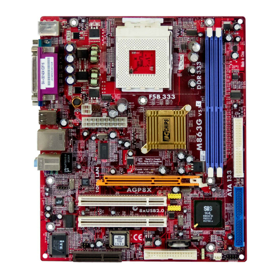
Page 11: Motherboard Components
Motherboard User’s Guide Motherboard Components ITEM LABEL COM PONENTS COLOR DDR1/2 184-pin DDR SDRA M sockets PURPLE IDE2 Primary/Sceondary IDE c onnector WHITE USB2/3 Front Panel USB headers Y ELLOW IDE1 Primary/Sceondary IDE c onnector BLUE Clear CMOS jumper Front Panel Sw itch/LED header COLOR SY SFA N1 System Fan connec tor... -
Page 12: I/O Ports
Chapter 2: Motherboard Installation I/O Ports This is a side view of the built-in I/O ports on the motherboard. Use the upper PS/2 port to connect a PS/2 pointing PS/2 Mouse device. PS/2 Keyboard Use the low er PS/2 port to connect a PS/2 keyboard. -
Page 13: Installing Memory Modules
Motherboard User’s Guide Installing Memory Modules This motherboard accommodates two 184-pin 2.5V DIMM sockets (Dual Inline Memory Module) for unbuffered DDR333/266 memory modules (Double Data Rate SDRAM), and maximum 2.0 GB installed memory. DDR SDRAM is a type of SDRAM that supports data transfers on both edges of each clock cycle (the rising and falling edges), effectively doubling the memory chip’s data throughput. -
Page 14: Jumper Settings
Chapter 2: Motherboard Installation Install any remaining DIMM modules. Jumper Settings Connecting two pins with a jumper cap is SHORT; removing a jumper cap from these pins, OPEN. JP2: Clear CMOS Jumper Use this jumper to clear the contents of the CMOS memory. You may need to clear the CMOS memory if the settings in the Setup Utility are incorrect and prevent your motherboard from operating. -
Page 15: Install The Motherboard
Motherboard User’s Guide Install the Motherboard Install the motherboard in a system chassis (case). The board is a Micro ATX size motherboard. You can install this motherboard in an ATX case. Make sure your case has an I/O cover plate matching the ports on this motherboard. Install the motherboard in a case. -
Page 16: Connecting Optional Devices
Chapter 2: Motherboard Installation Connecting Optional Devices Refer to the following for information on connecting the motherboard’s optional devices: AUDIO1 USB2 USB3 SPK1 SPK1: Speaker Header Connect the cable from the PC speaker to the SPK1 header on the motherboard. Signal SPKR AUDIO1: Front Panel Audio Header... - Page 17 Motherboard User’s Guide Locate the USB2/USB3 header on the motherboard. Plug the bracket cable onto the USB2/USB3 header. Remove a slot cover from one of the expansion slots on the system chassis. Install an extension bracket in the opening. Secure the extension bracket to the chassis with a screw.
-
Page 18: Install Other Devices
Chapter 2: Motherboard Installation Install Other Devices Install and connect any other devices in the system following the steps below. IDE2 IDE1 FDC1 Floppy Disk Drive The motherboard ships with a floppy disk drive cable that can support one or two drives. - Page 19 Motherboard User’s Guide Analog Audio Input Header If you have installed a CD-ROM drive or DVD-ROM drive, you can connect the drive audio cable to the onboard sound system. When you first start up your system, the BIOS should automatically detect your CD-ROM/DVD drive.
-
Page 20: Expansion Slots
Chapter 2: Motherboard Installation Expansion Slots This motherboard has one AGP, CNR and two 32-bit PCI slots. AGP1 PCI1 PCI2 CNR1 Follow the steps below to install an AGP/CNR/PCI expansion card. Locate the AGP, CNR or PCI slots on the motherboard. Remove the blanking plate of the slot from the system chassis. -
Page 21: Chapter 3 Bios Setup Utility
Motherboard User’s Guide Chapter 3 BIOS Setup Utility Introduction The BIOS Setup Utility records settings and information of your computer, such as date and time, the type of hardware installed, and various configuration settings. Your computer applies the information to initialize all the components when booting up and basic functions of coordination between system compo- nents. -
Page 22: Standard Cmos Setup Page
Chapter 3: BIOS Setup Utility Some options on the main menu page lead to tables of items with installed values that you can use cursor arrow keys to highlight one item, and press PgUp and PgDn keys to cycle through alternative values of that item. The other options on the main menu page lead to dialog boxes requiring your answer OK or Cancel by selecting the [OK] or [Cancel]. -
Page 23: Advanced Setup Page
Motherboard User’s Guide Advanced Setup Page This page sets up more advanced information about your system. Handle this page with caution. Any changes can affect the operation of your computer. CMOS SETUP UTILITY – Copyright (C) 1985-2003, American Megatrends, Inc. Advanced Setup Help Item 32 MB... -
Page 24: Features Setup Page
Chapter 3: BIOS Setup Utility DRAM CAS# Latency This item determines the operation of DRAM memory CAS (column address strobe). It is recommended that you leave this item at the default value. The 2T setting requires faster memory that specifically supports this mode. Auto detect DIMM/PCI Clock When this item is enabled, BIOS will disable the clock signal of free DIMM/PCI slots. -
Page 25: Power Management Setup Page
Motherboard User’s Guide Parallel Port Mode Use this item to set the parallel port mode. You can select ECP (Extended Capabilities Port). ECP Mode DMA Channel Use this item to assign a DMA channel to the parallel port. Parallel Port IRQ Use this item to assign IRQ to the parallel port. -
Page 26: Pci/Plug And Play Setup Page
Chapter 3: BIOS Setup Utility Power Management Use this item to enable or disable a power management scheme. If you enable power management, you can use the items below to set the power management operation. Both APM and ACPI are supported. Suspend Mode This item shows the status S1(Stop Clock) when the system enters the power- saving Suspend mode. -
Page 27: Bios Security Features Setup Page
Motherboard User’s Guide Primary Graphics Adapter This item indicates if the primary graphics adapter uses the PCI or the AGP bus. The default PCI setting still lets the onboard display work and allows the use of a second display card installed in an AGP slot. Allocate IRQ to PCI VGA If this item is enabled, an IRQ will be assigned to the PCI VGA graphics system. -
Page 28: Cpu Pnp Setup Page
Chapter 3: BIOS Setup Utility CPU PnP Setup Page This page helps you manually configure the mainboard for the CPU. The system will automatically detect the type of installed CPU and make the appropriate adjustments to the items on this page. CMOS SETUP UTILITY –... -
Page 29: Load Optimal Defaults
Motherboard User’s Guide CPU/System Temperature These items display CPU and system temperature measurement. FANs & Voltage Measurements These items indicate cooling fan speeds in RPM and the various system voltage measurements. Load Optimal Defaults This option opens a dialog box to ask if you are sure to install optimized defaults or not. -
Page 30: Chapter 4 Software & Applications
Chapter 4: Software & Applications Chapter 4 Software & Applications Introduction This chapter describes the contents of the support CD-ROM that comes with the motherboard package. The support CD-ROM contains all useful software, necessary drivers and utility programs to properly run our products. More program information is available in a README file, located in the same directory as the software. - Page 31 Motherboard User’s Guide The Browse CD button is a standard Windows command that you can check the contents of the disc with the Windows 98 file browsing interface. The Exit button closes the Auto Setup window. To run the program again, reinsert the CD-ROM disc in the drive;...
-
Page 32: Bundled Software Installation
Chapter 4: Software & Applications The support software will automatically install. Once any of the installation procedures start, software is automatically installed in sequence. You need to follow the onscreen instructions, confirm commands and allow the computer to restart as few times as needed to complete installing whatever software you selected.
Need help?
Do you have a question about the M863G and is the answer not in the manual?
Questions and answers