nilan CTS 600 Installation Instruction
Hide thumbs
Also See for CTS 600:
- User manual (25 pages) ,
- Installation instruction (25 pages) ,
- User manual (26 pages)

Related Manuals for nilan CTS 600


Summary of Contents for nilan CTS 600
- Page 1 Installation instruction CTS 600 by Nilan VPL 15 VPL 15 Top VPL 25 Version: 6.00, 12-03-2012 Software-version: 1.38...
-
Page 2: Table Of Contents
Ducting ............................7 Heating surface, water ........................8 Heating surface, electrical (retrofitting) ..................10 Starting and set up of the CTS 600 control ..................11 Starting ............................. 11 Set up of the CTS 600 control ....................11 Activating the service menu ...................... 12 Heating surface ......................... -
Page 3: Introduction
The unit can be equipped with different accessories e.g. hygrostat and filter box with pollen filter. Operating the unit is done with the CTS 600 control. The control has many functions such as menu based attendance, week programme, time controlled filter guard and adjustment of the velocity of the ventilator. -
Page 4: Power Supply
The VPL 15/15T/25 unit must be connected according to the attached electrical chart. The unit is delivered with 1m test cable for the CTS 600 panel. The panel should be connected to the CTS 600 control in the unit with cable type 2x2x0.25mm twisted in pairs. -
Page 5: Assembly Of Vpl 15/15T/25
Assembly of VPL 15/15T/25 When mounting the VPL-unit future service and maintenance should be considered. There is required a minimum of open space in front and behind the unit of 600mm . The system’s connection pieces and the pipes are connected with a flexible transition (flex pipes/sound flex pipes or the like). -
Page 6: Condensation Drain / Water Seal
Condensation drain / water seal The VPL unit is delivered with a 20mm condensation drain. (PVC, GF-fittings). The drain is placed under the discharge. The condensation drain should be carried with an even inclination of at least 1 cm per meter, frost-proof to the nearest outlet. -
Page 7: Ducting
Ducting We recommend that there are used ducts and fittings with rubber packing that meet sealing class B and that the connections between the unit and the ducting are made with 1 metre sound absorb- ing flexible transitions as regards sound reduction. The ducts should be shortened with a hacksaw or an angle grinder and laid out according to the working drawing. -
Page 8: Heating Surface, Water
The heating surface is to be installed in the inlet ducting just after the VPL unit. The heating sur- face must also be activated in the CTS 600 control as described on page 13. The mixing loop can be constructed as suggested below. - Page 9 Danfoss Actuator should be connected to the clamps in the electrical box. B3 frost-protection should be connected to the CTS 600 PCB in the ventilation unit. See electrical chart. This document may be subject to change...
-
Page 10: Heating Surface, Electrical (Retrofitting)
Heating surface, electrical (retrofitting) Electrical heating surface should be installed in the ducting (Ø160/Ø200). When retrofitting an elec- trical heating surface it should be activated in the 600 control panel as described on page 15. Power supply must be installed by an authorized electrician. See electrical chart for the ventilation unit and electrical chart for LMC200 PCB A - H. -
Page 11: Starting And Set Up Of The Cts 600 Control
Set up of the CTS 600 control In this passage we will go through the service menu of the CTS 600 control. For daily use of the CTS 600 control please see the CTS 600 directions. (delivered together with the VPL). -
Page 12: Activating The Service Menu
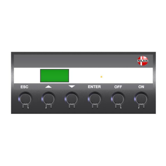
Activating the service menu Press q and ENTER at the same time for 10 seconds. The service menu is now available. Press q multiple times until the panel shows SERVICE. Press ENTER to enter the service menu. It is now possible to move around in the menu by using pq. The headlines of the service menu are shown below: ENTER HEATING... -
Page 13: Heating Surface
The unit can be equipped with a heating surface. It is possible to retrofit a heating surface. The surface must be activated in the CTS 600 control in order to function together with the unit and for the frost-protection to be active. -
Page 14: Air Exchange
It is possible to delay the starting of the fan in order to give time to the register to open. Use of t he CTS 600 panel : - pr ess ESC t o go one st ep back i n t he m enu... -
Page 15: Defrost
” ” indicates that the menu point flashes and can be set to another value Use of t he CTS 600 panel : - pr ess ESC t o go one st ep back i n t he m enu... -
Page 16: Temp. Control
” ” indicates that the menu point flashes and can be set to another value Use of t he CTS 600 panel : - pr ess ESC t o go one st ep back i n t he m enu... -
Page 17: Inlet Control
” ” indicates that the menu point flashes and can be set to another value Use of t he CTS 600 panel : - pr ess ESC t o go one st ep back i n t he m enu... -
Page 18: Room Control
” ” indicates that the menu point flashes and can be set to another value Use of t he CTS 600 panel : - pr ess ESC t o go one st ep back i n t he m enu... -
Page 19: Restart
The setting HP/LP in the Restart menu may not be used under normal conditions. Use of t he CTS 600 panel : - pr ess ESC t o go one st ep back i n t he m enu... -
Page 20: Preset
” ” indicates that the menu point flashes and can be set to another value Use of t he CTS 600 panel : - pr ess ESC t o go one st ep back i n t he m enu... -
Page 21: Manual
” ” indicates that the menu point flashes and can be set to another value Use of t he CTS 600 panel : - pr ess ESC t o go one st ep back i n t he m enu... -
Page 22: System Dimension
System dimension Right Front Left Figure 17: System dimension 1. Fresh air intake. 5. Compressor 9. Inlet fan 2. Exhaust 6. Condensator (hidden) 10. Exhaust fan 3. Inlet 7. Evaporator 11. Condensation drain 4. Discharge 8. Electrical connections Dimensions in mm: VPL15 Ø160 Ø20... -
Page 23: Accessories / Spare Parts
Accessories / spare parts VPL 15 Filter types Qty. Nilan item no. F5 (exhaust) 3953 F7 (inlet) 3952 VPL 15T Filter types Designation Nilan item no. T-filter, comlete Ø160mm 8481 Filter for item no. 8481 Ø160mm 8504 VPL 25 Filterklasse Designation Qty.
Need help?
Do you have a question about the CTS 600 and is the answer not in the manual?
Questions and answers