Table of Contents
Advertisement
Advertisement
Table of Contents

Related Manuals for Spectrum 802.11ac Wave 2


Summary of Contents for Spectrum 802.11ac Wave 2
-
Page 1: User Guide
User Guide 802.11ac Wave 2 Router... - Page 2 Table of Contents 1 Hardware Setup .........................2 1.1 Getting To Know Your WiFi Router.......................2 1.2 Unpack WiFi Router’s box........................3 1.3 Hardware Features............................4 1.3.1 Front Panel............................4 1.3.2 Rear Panel............................5 1.4 Position Your WiFi Router........................6 2 Login to your WiFi Router Web GUI ..............7 2.1 Login................................7 2.2 Wizard Setup.............................10...
-
Page 3: Hardware Setup
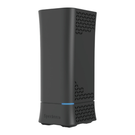
1 Hardware Setup 1.1 Getting To Know Your WiFi Router This product is designed for the In-Home and Business WiFi service for Spectrum customers. With a custom industrial design, this WiFi Router can be placed in a central location to deliver superior WiFi network coverage. -
Page 4: Unpack Wifi Router's Box
1.2 Unpack WiFi Router’s box Open the box and remove the WiFi Router, power adapter, Quick Start Guide, WiFi Network Name and Password Sticker and Ethernet cord. Power Adapter WiFi Router Figure 1. Check the package contents The box contains the following items: ·... -
Page 5: Hardware Features
1.3 Hardware Features Before setup please take a moment to become familiar with the front Panel and Rear Panel of your WiFi Router. Pay particular attention to the LED on the front panel. You should know the surface structure of your WiFi Router only. 1.3.1 Front Panel The WiFi Router front and back panels feature the status LED and buttons as shown in the following figure... -
Page 6: Rear Panel
1.3.2 Rear Panel There are Ethernet and USB connections and buttons shown in the following figure. Figure 3. WiFi Router rear panel · Factory Reset (pinhole): Press the pinhole and hold over 5 seconds, the WiFi Router will reset to factory. ·... -
Page 7: Position Your Wifi Router
1.4 Position Your WiFi Router The WiFi Router lets you access your network from virtually anywhere within the operating range of your wireless network. However, the wireless communicating distance varies significantly due to placement of the WiFi Router. For example, the thickness and number of walls the wireless signal passes through can limit the range. -
Page 8: Login
2 Sign-In Your WiFi Router Web GUI The WiFi Router contains an intuitive graphical user interface (GUI) based on web, which lets administrator easily configure its features through a web browser. 2.1 Sign-In 1. Open a web browser, then key in the WiFi Router’s default IP address: http://192.168.1.1, and click Enter key in the keyboard;;... - Page 9 On the right top side, there are two command buttons: Change Password and Logout. Please click the Logout button when administrator intends to leave the Web GUI. When the Change Password button has been clicked, the browser will navigate to the corresponding webpage.
- Page 10 On this page, user should just type in new password in New Password and Retype New Password, then click Apply button. Web GUI user sign in password will be changed.
-
Page 11: Wizard Setup
Connection Type: There are 5 kinds of connection types: DHCP, PPPoE, Static, PPTP and L2TP. DHCP: Enable WiFi Router to obtain IP addresses automatically. This setting is the default for Spectrum services. More types of settings, reference 2.3.4 WAN Setup. -
Page 12: Network Setup
· WAN MAC: MAC address of WAN port. · Host Name: This field allows lets administrator provide a name for WiFi Router. · DNS 1 & DNS 2: Either of them indicates the IP address of a DNS Server. · Click Next. - Page 13 2. WiFi Password: A password used by WiFi Router to authenticate wireless connections. These are defaulted from the printed WiFi password on the back of the WiFi Router. You can change it here, but they would no longer match the sticker on your router.
-
Page 14: Basic Setup
2.3 Basic Setup 2.3.1 Router From the navigation panel, go to Basic > Router. NOTE: Click Reset Icon in the Web GUI is used to restart the WiFi Router. The WiFi Router hardware Factory Reset (pinhole) was pressed and hold over 5 seconds, it will reset to factory. - Page 15 Wireless: This module is implemented to configure some basic settings for WiFi Router’s wireless connection. 1. WiFi Network Name: A unique name that identifies the wireless network. Wireless device can automatically detect all networks within its communication range. The maximum length of a network name (SSID) is 32 characters.
-
Page 16: Wps Setup
2.3.2 WPS Setup WPS (WiFi Protected Setup) is a wireless security standard that lets the device easily connect a WiFi network. You can trigger the WPS function via the PIN code or WPS button. Steps to enable WPS (WiFi Protected Setup): 1. - Page 17 8. PIN Code: The WPS PIN code which clients use to connect with the WiFi Router. 9. In the WPS Method field, select Push Button or Client PIN code. If you select Push Button, go to step 10. If you select Client PIN code, go to step 11. 10.
-
Page 18: Lan Setup
2.3.3 LAN Setup This module makes it easier for administrator to modify the default LAN IP Address. Steps to modify LAN IP settings: 1. From the navigation panel, go to Basic > Router. 2. LAN IP: The LAN IP address of the WiFi Router. Its default value is 192.168.1.1. In IP-based networks, packets are sent to the network devices' specific IP addresses. -
Page 19: Wan Setup
2.3.4 WAN Setup Click WAN button to configure the WAN connection settings: 1. Connection Type: Choose the Internet Service type. There are five options are DHCP, PPPoE, Static, PPTP, and L2TP. Consult your ISP if you are unsure what kind of WAN connection type to select. 2. - Page 20 3. If you select PPPoE: · Username: This field is only available when you set the WAN Connection Type as PPPoE, PPTP or L2TP. · Password: This field is only available when you set WAN Connection Type as PPPoE, PPTP or L2TP.
- Page 21 4. If you select Static, below show the steps to set • IP: If WAN connection requires a static IP address, key in the IP address in • Subnet Mask: this field. If WAN connection requires a static IP address, key in the subnet mask in •...
- Page 22 5. If you select PPTP: • Username: This field is only available when you set the WAN Connection Type as PPPoE, PPTP or L2TP. • Password: This field is only available when you set WAN Connection Type as PPPoE, PPTP or L2TP. •...
- Page 23 6. If you select L2TP: Please reference to PPTP above for relevant settings descriptions and enter the required information.
-
Page 24: Parental Control
2.3.5 Parental Control Parental Control lets administrator control the Internet access of the client. - Page 25 Steps to set parental control function: 1. From the navigation panel, go to Basic > Parental Control. 2. Enable Parental Control: Select On to enable parental control, Select Off to disable parental control. 3. Client Name: Select client from the list. The name in the list stands for the client that is communicating with the WiFi Router.
-
Page 26: Services
2.3.6 Services 2.3.6.1 USB Printer Sharing USB Printer sharing lets administrator plug a USB printer to WiFi Router’s USB port and set up the print server. Steps to set up USB Printer sharing: 1. From the navigation panel, go to Basic > Service > USB Printer sharing > Add Printer. 2. - Page 27 4. Printer tab displays whether your printer is operating correctly with the print server, as below. 5. To check whether your printer is working correctly or not, input the LAN address (192.168.1.1) for the printer in Windows Finder. 6. Double-click the printer icon and if you see the status interface as shown below, the installation was successful.
- Page 28 7. You can view print status information in the Print Jobs tab. · Active: All active jobs, including processing and pending jobs. · Processing: The job currently processing/communicating print data. · All Jobs: All print jobs. ...
-
Page 29: Ftp Server
2.3.6.2 FTP Server FTP Server enables an FTP server to share files from USB disk to other devices via your local area network or via the Internet. This page shows information about the FTP Server. For set up FTP Server, go to Advanced > Servers > FTP Server. Display information on FTP Server: 1. - Page 30 2.3.6.3 Samba Samba Share lets you set up the accounts and permissions for the Samba service. This page shows information about the Samba Server. For Samba setup go to Advanced > Servers > Samba. · From the navigation panel, go to Basic > Services > Samba. ·...
- Page 31 2.3.6.4 WebDAV The client can write operations in WebDAV directory with appropriate permissions. This page shows information about the WebDAV Server. To set up WebDAV go to Advanced > Servers > WebDAV. 1. From the navigation panel, go to Basic > Services > WebDAV. 2.
- Page 32 6. Outside Access: The port number of external service ports via HTTP (default value: 8080). The port number of external service ports via HTTPS 7. Outside Access HTTPS: (default value: 8443). Click to safely remove the disk. When the USB disk is ejected 8.
- Page 33 2.3.6.5 DLNA DLNA (Digital Living Network Alliance) lets you share audio, image and video. Your WiFi Router lets DLNA-supported devices access multimedia files from the USB disk connected to your WiFi Router. This page shows information about the DLNA Server. To setup DLNA server, go to Advanced >...
- Page 34 2.3.6.6 AFP An AFP server is a kind of network file sharing server based on AFP protocol implementation, mainly used for file sharing between Linux and MAC systems. This page shows information about the AFP server. To setup AFP, go to Advanced > Servers > AFP. Steps to set AFP: 1.
- Page 35 2.3.6.7 NFS Network File System Server is used to share the USB disk with clients via network. Clients can mount the remote disk to a local directory for a faster speed than using a Samba server. This page shows information about the NFS Server. To setup NFS, go to Advanced > Servers >...
-
Page 36: System
2.3.7 System This module lets sign in user do some settings, such as changing your own sign in password, selecting time-zone and adding NTP server. If you changed the password, the user password to sign in SSH will be changed. Steps to set the System settings: 1. -
Page 37: Advanced Setup
2.4 Advanced Setup 2.4.1 Network 2.4.1.1 WAN Settings 2.4.1.1.1 Internet Settings WiFi Router supports several WAN connection types. Select the type from the WAN Connection Type dropdown menu. - Page 38 Steps to configure WAN connection settings: 1. From the navigation panel, go to Advanced > Network > WAN > Internet. 2. WAN Connection Type: Choose the Internet Service Provider type. There are 5 options: DHCP, PPPoE, Static, PPTP and L2TP. If you are unsure which type to select, please consult your ISP.
- Page 39 18. DHCP Query Frequency: Some ISP blocks MAC addresses if the device makes DHCP queries too often. To prevent this, change the DHCP Query Frequency. In the default Aggressive mode, if your WiFi Router does not get a response from the ISP, it sends another query after 20 seconds and makes three more attempts.
- Page 40 2.4.1.1.2 DDNS DDNS(Dynamic DNS)makes administrator can get access to WiFi Router even though it’s working within a local network. Steps to set up DDNS: 1. From the navigation panel, go to Advanced > Network > WAN > DDNS. 2. Enable the DDNS Client: Yes means enable DDNS function, No means disable DDNS function.
- Page 41 2.4.1.1.3 UPnP UPnP (Universal Plug and Play) let devices (such as routers, televisions, stereo systems) be controlled via an IP-based network with or without a central control unit. Under the help of UPnP, one device can be discovered once it has connected to network, then device can be remotely configured to support P2P applications, interactive gaming, video conferencing, and web or proxy servers.
-
Page 42: Port Triggering
2.4.1.1.4 Port Triggering Port triggering mechanism forwards the packets from the Incoming Port to the local client when the local client makes an outgoing connection through a predetermined port/port range (Triggering Port). Steps to set up Port Triggering: 1. From the navigation panel, go to Advanced > Network > WAN > Port Triggering. 2. -
Page 43: Port Forwarding
2.4.1.1.5 Port Forwarding Port forwarding lets remote computers access a specific service within a LAN-side network. It can redirect a network request from one address/ports (Public IP/Port) to another (Local IP/Port). Steps to set up Port Forwarding: From the navigation panel, go to Advanced> Network> WAN>Port Forwarding. Click the Add button to add the port forwarding rules. - Page 44 3. Well Known Server List: Select a pre-defined Server list from the drop-down menu and the Port Forwarding List will be auto-filled. 4. Well Known Game List: Select a game from the Server list and the Port Forwarding List will be auto-filled. 5.
- Page 45 2.4.1.1.6 DMZ Virtual DMZ module exposes one client to the Internet, allowing this client to receive all inbound packets directed to a Local Area Network. For IPv4, inbound traffic from the Internet is usually discarded and routed to a specific client only if port forwarding or a port trigger has been configured on the network.
- Page 46 6. IPv6 prefix for DMZ setting: The IPv6 DMZ address must be in the range of IPv6 prefix. Show it for user to set valid DMZ address. 7. Click Apply.
- Page 47 2.4.1.1.7 NAT Pass Through NAT Pass Through lets a Virtual Private Network (VPN) connection pass through the WiFi Router to the network server. Steps to set up NAT Pass Through: To configure NAT Pass Through settings, go to Advanced > Network > WAN > NAT Pass Through.
- Page 48 7. H.323 Passthrough: Enable or disable. H.323 is a recommendation from the ITU Telecommunication Standardization Sector (ITU-T) that defines the protocols to provide audio-visual communication sessions on any packet network. 8. SIP Passthrough: Enable or disable. The Session Initiation Protocol (SIP) is a communications protocol for signaling and controlling multimedia communication sessions.
-
Page 49: Lan Settings
2.4.1.2 LAN Settings 2.4.1.2.1 LAN The LAN IP module lets administrator modify LAN-side IP address of the router. Steps to modify the LAN IP settings: 1. From the navigation panel, go to Advanced > Network > LAN > LAN IP. 2. -
Page 50: Dhcp Server
2.4.1.2.2 DHCP Server DHCP server can assign each client an IP address and informs the client of DNS server’s IP, default gateway’s IP and etc. This WiFi Router can allocate up to 253 IP addresses for LAN- side devices. Steps to configure the DHCP server: 1. - Page 51 3. Domain Name: Domain Name for clients who request IP Address from DHCP Server. This field only contains alphanumeric characters and dash symbols. 4. IP Pool Starting Address: Starting address that can be allocated to LAN-side devices. 5. IP Pool Ending Address: Ending address that can be allocated to LAN-side devices.
-
Page 52: Wireless Settings
2.4.1.3 Wireless Settings 2.4.1.3.1 Basic Basic settings allow you to set up the basic wireless settings. Steps to set up the basic wireless settings: 1. From the navigation panel, go to Advanced > Network > Wireless > Basic. 2. Frequency: Select the frequency band to configure. - Page 53 WiFi Password: Requires a password of 8-63 characters (letters, numbers or a combination) or 8 - 64 hex digits to start the encryption process. Protected Management Frames: Protected Management Frames is a feature to protect some types of management frames like deauthorization, disassociation and action frames.
- Page 54 2.4.1.3.2 WPS WPS (WiFi Protected Setup) is a wireless security standard that lets you easily connect devices to a wireless network. You can trigger the WPS function via the PIN code or WPS button. Reference 2.3.2 WPS Setup...
- Page 55 2.4.1.3.3 ACL ACL can be used to allow or disallow one device to associate to the AP/ Router. Steps to set up the ACL: 1. From the navigation panel, go to Advanced > Network > Wireless > ACL. 2. Frequency: In the frequency field, select the frequency band that you want to use for the ACL settings.
- Page 56 2.4.1.3.4 Radio Administrator can set some advanced feature for radio of the WiFi Router.
- Page 57 Steps to set Radio: From the navigation panel, go to Advanced > Network > Wireless > Radio. 2. Frequency: Selecting the frequency band that the WiFi Router is running. 3. Enable Wireless Scheduler: Switch wireless schedule on or not. 4. Date to Enable (Weekdays): Select weekdays to enable Wi-Fi.
- Page 58 20. DCS Enable: Enable or disable DCS function which is a feature to detect and avoid CW interference. 21. Radio Resource Management: Enables or disables 802.11k 22. When done, click Apply.
- Page 59 2.4.1.3.5 Advanced The Professional module provides advanced configuration options. NOTE: We recommend that administrators use the default settings.
- Page 60 In this module, administrator can configure the followings: From the navigation panel, go to Advanced > Network > Wireless > advanced. 2. Frequency: Select the frequency band to configure professional settings. 3. WiFi Network Name: A name whose length is less than 32 characters is used to identify a wireless network.
- Page 61 2.4.1.4 IPv6 The module is used to set some basic functions related to IPv6. For IPv6 service is not yet widely available, contact your ISP to make sure whether IPv6 service is provided.
- Page 62 Steps to set up IPv6: From the navigation panel, go to Advanced > Network > IPv6. Select IPv6 connection type to configure Disable, 2. Connection Type: Native, Static IPv6. Set the wan interface’s ipv6 address. 3. WAN IPv6 Address: Set the wan interface’s ipv6 prefix length. 4.
- Page 63 22. IPv6 DNS Server 2: IPv6 address for DNS server. 23. IPv6 DNS Server 3: IPv6 address for DNS server. 24. Port Ranges Valid for Port Forwarding: The "port ranges" are set by Map-T mode, and the port setting for port forwarding must be in these ranges.
- Page 64 2.4.1.5 Parental Control Refer to 2.3.5 Parental Control for relevant setting descriptions. 2.4.1.6 Multicast Enable multicast. The sender and receiver achieve a point to multipoint connection. Steps to set up Multicast: From the navigation panel, go to Advanced > Network > Multicast. 2.
- Page 65 4. Enable IGMP/MLD Snooping: Check [Yes] to enable snooping and Check [No] to disable snooping. IGMP/MLD snooping is the process of listening to Internet Group Management Protocol (IGMP) / Multicast Listener Discovery (MLD) network traffic. The feature lets a network switch listen in on the IGMP/MLD conversation between hosts and WiFi Routers.
- Page 66 2.4.1.7 Routing This module can be used to build a static NAT table between WAN IP address and LAN IP address. Steps to set up Routing: From the navigation panel, go to Advanced > Network > Routing. 2. Enable 1:1 NAT: Check [Yes] to enable this function, check [No] to disable this function. 3.
-
Page 67: Services Config
2.4.2 Services Config 2.4.2.1 USB Printer sharing Refer to 2.3.6.1 USB Printer sharing for relevant setting descriptions. 2.4.2.2 FTP Server FTP Server enables an FTP server to share files from USB disk to other devices via your local area network or via the Internet. To set up FTP Server: From the navigation panel, go to Advanced >... - Page 68 3. Click On/Off to enable/disable Internet access to FTP service. To create a new account: Add new account. 2. In the Account and Password fields, key in the name and password of your network client. Retype the password to confirm. Click Add to add the account to the list. To add a folder: Add new folder.
- Page 69 2.4.2.3 Samba Samba Share lets you set up the accounts and permissions for the Samba service. To set up Samba: From the navigation panel, go to Advanced > Services > Samba Server. 2. Connect an external USB hard disk drive or USB flash drive to the WiFi Router, and your device will be displayed here.
- Page 70 To add a folder: Add new folder. 2. Enter a folder name. The folder that you created will be added to the folder list. To set up permissions on the folder for Samba server: From the list of folders, choose one of the shared folders and add the share name, and choose the type of access permission that you want to assign for specific users: ·...
- Page 71 2.4.2.4 WebDAV The client can write operation in WebDAV directory with appropriate permissions. To set up WebDAV: From the navigation panel, go to Advanced > Services > WebDAV Server. 2. Connect an external USB hard disk drive or USB flash drive to your WiFi Router, and your device will be displayed here.
- Page 72 To add a folder: Add new folder. 2. Enter a folder name. The folder that you created will be added to the folder list. To set up permissions on the folder for WebDAV server: From the list of folders, choose one of the shared folders and add the share name, then choose the type of access permission that you want to assign for specific users: ·...
- Page 73 2.4.2.5 DLNA DLNA (Digital Living Network Alliance) lets you share audio, image and video. Your WiFi Router lets DLNA-supported devices access multimedia files from the USB disk connected to your WiFi Router. To set up DLNA: From the navigation panel, go to Advanced > Services > DLNA Server. 2.
- Page 74 Shared Content Type: The media type that will be shared by the DLNA server: audio, image, video. 8. Safely Remove Disk: Click to safely remove the disk. When the USB disk is ejected successfully, the USB status shows 'No device '. 9.
- Page 75 2.4.2.6 AFP An AFP server is a kind of network file sharing server based on AFP protocol implementation, mainly used for file sharing between Linux and MAC systems. To set up AFP: From the navigation panel, go to Advanced > Services > AFP Server. 2.
- Page 76 To set up permissions on the folder for AFP server: From the list of folders, choose one of the shared folder and add the share name, and choose the type of access permission that you want to assign for specific users: ·...
- Page 77 2.4.2.7 NFS Network File System Server is used to share the USB disk with clients via network. Clients can mount the remote disk to a local directory for a faster speed than using a Samba server. To setup NFS: From the navigation panel, go to Advanced > Services > NFS Server. 2.
- Page 78 Let clients access the destination shared partition with the "read only" permission. > *,ro Safely Remove Disk: Click to safely remove the disk. When the USB disk is ejected successfully, the USB status shows 'No device '.
-
Page 79: Security
2.4.3 Security 2.4.3.1 VPN VPN (Virtual Private Network) provides a secure communication to a remote computer or remote network using a public network such as the Internet. 2.4.3.1.1 PPTP VPN Server The VPN server lets administrator get access to home network anytime, anywhere. NOTE: Before setting up a VPN connection, you need the IP address or domain name of the VPN server you are trying to access. - Page 80 Advanced VPN server settings, as below. · Broadcast Support: Turns on broadcast relay to clients from the WiFi Router. · Authorization Mode: Select Authorization Mode. · MPPE Encryption: Select MPPE Encryption type. · Connect to DNS Server Automatically: DNS of PPTP clients. ·...
-
Page 81: Openvpn Server
2.4.3.1.2 OpenVPN Server The VPN server lets administrator get access to home network anytime, anywhere. Steps to set OpenVPN Server: From the navigation panel, go to Advanced > Security > VPN > OpenVPN Server. · Enable VPN Server: Enable or disable OpenVPN server function. ·... - Page 82 · Interface Type: "TUN" will create a routed IP tunnel, "TAP" will create an Ethernet tunnel. · Protocol: TCP or UDP server. · Server Port: The TCP/UDP port which OpenVPN server will listen · Firewall: Firewall configuration for VPN server. Auto will create complete firewall configurations, External only will create basic firewall configurations and Custom will not create any firewall configurations.
- Page 83 · Username / Password Auth. Only: Yes requires only username and password for authentication, No also requires authentication certificate. · Extra HMAC Authorization: If enabled, a tls_auth key will be used on the server. Every client must also have the key. ·...
-
Page 84: Vpn Client
2.4.3.1.3 VPN Client View the VPN server list and add profiles. There are three types of VPN servers: PPTP, L2TP and Open VPN. Steps to setup a VPN Client: From the navigation panel, go to Advanced > Security > VPN > VPN Client. VPN Sever list is displayed. - Page 85 Enable Default Route: Check [Yes] to use default route acquiring from VPN Server. Check [No] to use general default route. Description: Enter a description for reference. VPN Server: VPN Server IP address or URL. Username: VPN authentication username. Password: VPN authentication password. PPTP Options: PPTP Encryption method.
-
Page 86: Ipv4 Firewall
2.4.3.2 IPv4 Firewall Enable the firewall to protect local area network against attacks from outside. Firewall filters the incoming and outgoing packets based on rules. NOTE: Firewall is enable by default. 2.4.3.2.1 Common Steps to set up basic Firewall settings: From the navigation panel, go to Advanced >... - Page 87 2.4.3.2.2 Net Service Filter Net Service Filter can work in either White List or Black List mode. When running in White List mode, it only lets certain packets get through the WiFi Router. While in Black List mode, it only blocks certain packets passthrough. Steps to set Net Service Filter: From the navigation panel, go to Advanced>...
- Page 88 Port Range: For source or destination port range, you can either: a) enter a specific port, such as "95"; b) enter ports within a range such as "103:315", ">100", or "<65535". Destination IP: For source or destination IP address, you can: a) enter a specific IP address such as "192.168.122.1";...
- Page 89 2.4.3.2.3 Client ACL Client ACL can forbid the client from accessing to the WiFi Router. The client in the Client ACL List can’t visit the resource of WiFi Router and the internet. Steps to set up Client ACL: From the navigation panel, go to Advanced> Security> IPv4 Firewall> Client ACL. 2.
-
Page 90: Ipv6 Firewall
2.4.3.3 IPv6 Firewall 2.4.3.3.1 Common Steps to set up common IPv6 Firewall: From the navigation panel, go to Advanced > Security >IPv6 Firewall > Common. 2. Enable Firewall: Enable or disable the IPv6 firewall. When disabled, all IPv6 packages can input WiFi Router, output WiFi Router and forward without any limitation. - Page 91 2.4.3.3.1 Allow Services Allow Services allows various types of service rules including protocol like TCP/UDP and ICMPv6 Message Type. It will allow certain packets and drop the other IPv6 packets from WAN-side to LAN-side. Steps to set up IPv6 Firewall: From the navigation panel, go to Advanced >...
- Page 92 Protocol: The protocol the service uses to transport the packages e.g. (UDP, TCP). ICMPv6 Message Type: Make WiFi Router process the defined types of ICMPv6 packet from specified host. 10. Local Host: IPv6 address of the host. 11. Add/Delete: Click to add/delete the profile.
-
Page 93: Airtime Fairness
2.4.4 QoS QoS(Quality of Service, QoS) module provides different services according to the priority of applications, users, or data flows. In a word, it can guarantee a certain level of performance to a data flow. 2.4.4.1 Airtime Fairness The ATF(Airtime Fairness, ATF) module supports mixing rates of WiFi devices to achieve better performance in busy/intense environments. - Page 94 Percentage of Air Time: Set the percentage of SSID which will be used for ATF control. MAC: Select client by MAC address and set the percent which will be used for ATF control. 8. Click Apply.
- Page 95 2.4.4.2 Common Set up queue and down queue type, Decided in the queue page we can operate the type of queue, and set uplink and downlink limit, Limit our uplink and downlink transmission rate. Steps to set it: From the navigation panel, go to Advanced > QoS > Common. QoS Enable: Set the switch of CPE QOS function through Web page.
- Page 96 2.4.4.3 Queue Create an upstream queue and a downstream queue to classify traffic of different types into the upstream or downstream queue. Up queue and down queue type based on common page selection. In the queue page on the queue. Add, delete, modify. 2.4.4.3.1 UpStream Queue Steps to set queue: From the navigation panel, go to Advanced >...
- Page 97 2.4.4.3.2 DownStream Queue Steps to set queue: From the navigation panel, go to Advanced > QoS > Queue > DownStream Queue. Enable: Enables or disables this queue. Weight: Weight of this queue in case of Weighted Round Robin or Weighted Fair Queuing, but only used for queues of equal precedence.
- Page 98 2.4.4.4 Classification According to the characteristics of the data flow, traffic is classified and then queued to the specified upstream or downstream queues. Classification Display page: Display classification table (Simple information). Steps to set up Classification: From the navigation panel, go to Advanced > QoS > Classification. 2.
- Page 99 Enable: Disable or enable this classification function. Base On: It is a fast classification, (can be based on Client, Custom, Server, SSID, APP). Name: Define this classification alias name. 10. Queue Type: Select the existing queue (upstream or downstream). Queue Name: Only display.
-
Page 100: Admin
2.4.5 Admin 2.4.5.1 System The System page lets you configure your WiFi Router settings. If you changed the password, the user password used to sign in SSH will be changed. Steps to set System: From the navigation panel, go to Advanced > Admin > System. 2. - Page 101 5. Remote Log Server: IP address of a syslog server to which log messages will be sent in addition to the local destination. 6. Time Zone: Default time-zone is America/ New York. 7. Auto Logout: Auto sign out after a specified time. 8.
- Page 102 2.4.5.2 Configuration Steps to save/reset/restore WiFi Router’s configuration: From the navigation panel, go to Advanced > Admin > Configuration. 2. Click Save, and then the browser will automatically download WiFi Router’s setting files. 3. Click Reset to Default, this will this resets all settings to factory default settings. 4.
- Page 103 2.4.5.3 Log System Log contains logs on network activities in the WiFi Router. Steps to set System log: From the navigation panel, go to Advanced > Admin > Log. 2. Clear: Clear contents in log file. 3. Save: Download log file from WiFi Router. 4.
- Page 104 2.4.5.4 Reboot Click the Reboot button, the WiFi Router will restart.
-
Page 105: Tools
2.4.6 Tools 2.4.6.1 Diagnostic Tools Various diagnostic tools are available such as ping, ping6, traceroute and nslookup. Steps to use Diagnostic Tools: From the navigation panel, go to Advanced> Tools> Diagnostic Tools 2. Method: Choose a specified method to test network. 3. -
Page 106: Wake On Lan
2.4.6.2 Wake on LAN Wake on LAN is a power management function. It lets network admins wake up LAN side devices from standby or hibernation mode. This function requires motherboard support on LAN-side devices. Steps to set Wake on LAN: From the navigation panel, go to Advanced>... -
Page 107: Status
2.4.7 Status 2.4.7.1 System Information System Information displays basic System, WAN, LAN and USB information. From the navigation panel, go to Advanced > Status > System Information. - Page 108 2.4.7.2 Wireless Wireless shows status information for wireless clients. From the navigation panel, go to Advanced > Status >Wireless. 2.4.7.3 DHCP Lease Show DHCP Lease status information, including MAC, IP and Hostname information. From the navigation panel, go to Advanced > Status > DHCP Lease.
-
Page 109: Routing Table
2.4.7.4 Routing Table Show IPv4 and IPv6 routing table and status information. From the navigation panel, go to Advanced > Status > Routing Table. -
Page 110: Connection List
2.4.7.5 Port Forwarding This module is used to show the WiFi Router's port forwarding rules information, which contains both Port Forwarding module's rules and UPnP module's rules. From the navigation panel, go to Advanced > Status > Port Forwarding. 2.4.7.6 Connection List Show active connections status information. -
Page 111: Snooping Table
2.4.7.7 IPv6 Information Display details on WAN and LAN IPv6 information. From the navigation panel, go to Advanced > Status > IPv6 Information. 2.4.7.8 Snooping Table Displays snooping table for client joins/leaves for both wired and wireless client streams. From the navigation panel, go to Advanced > Status > Snooping Table. -
Page 112: Current Users
2.4.7.9 Current Users Display current user who is permitted to get access to Internet through the router. From the navigation panel, go to Advanced > Status > Current User. - Page 113 2.4.7.10 Blocked Users Display current users who are not permitted to get access to Internet through the router. From the navigation panel, go to Advanced > Status > Blocked User.
-
Page 114: Fcc Statement
3 FCC Statement Federal Communication Commission Interference Statement This equipment has been tested and found to comply with the limits for a Class B digital device, pursuant to Part 15 of the FCC Rules. These limits are designed to provide reasonable protection against harmful interference in a residential installation. - Page 115 IMPORTANT NOTE: FCC Radiation Exposure Statement: This equipment complies with FCC radiation exposure limits set forth for an uncontrolled environment. This equipment should be installed and operated with minimum distance 21 cm between the radiator & your body.
Need help?
Do you have a question about the 802.11ac Wave 2 and is the answer not in the manual?
Questions and answers