Table of Contents
Advertisement
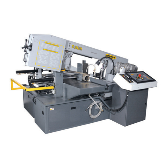
S20A NA
2008
393298
THANK YOU,
On behalf of everyone at HYD . MECH, we would like to thank and congratulate you on your decision to purchase a
HYD . MECH band saw.
Your new machine is now ready to play a key role in increasing the efficiency of your operation, helping you to reduce
cutting costs while boosting quality and productivity.
To ensure you are maximizing the power and versatility of your new HYD . MECH band saw, please take the time to
familiarize yourself and your employees with the correct operation and maintenance procedures as outlined in this
manual.
We sincerely appreciate the confidence you have demonstrated in purchasing our product and look forward to building a
long and mutually beneficial relationship.
Thank-you.
HYD . MECH GROUP LIMITED
P.O. BOX 1659
Woodstock, Ontario Canada, N4S 0A9
Phone: (519) 539-6341
Service 1-877-237-0914
Sales 1-877-276-SAWS(7297)
Fax (519) 539-5126
e-mail, info@hydmech.com
Printed NOVEMBER 2009
1
Advertisement
Table of Contents
Troubleshooting

Related Manuals for Hyd-Mech 393298


Summary of Contents for Hyd-Mech 393298
- Page 1 S20A NA 2008 393298 THANK YOU, On behalf of everyone at HYD . MECH, we would like to thank and congratulate you on your decision to purchase a HYD . MECH band saw. Your new machine is now ready to play a key role in increasing the efficiency of your operation, helping you to reduce cutting costs while boosting quality and productivity.
- Page 3 TABLE OF CONTENTS SECTION 0 - SAFETY INSTRUCTIONS SUMMARY ............................0.1 BASIC RULES ..........................0.4 RESPONSIBILITIES OF THE OWNER ...................0.5 RESPONSIBILITIES OF THE OPERATOR AND MAINTENANCE PERSONNEL ......0.6 SAFETY HAZARD LABELS ......................0.9 LOCATION AND PART NUMBERS OF SAFETY HAZARD LABELS ...........0.10 SECTION 1 - INSTALLATION SAFETY PRECAUTIONS ........................1.1 LIFTING THE S20A WITH A FORK LIFT ..................1.2 FOUNDATION, LEVELLING AND ANCHORING ................1.3...
- Page 4 SECTION 3 – MAINTENANCE AND TROUBLESHOOTING SAFETY DURING MAINTENANCE AND TROUBLESHOOTING ..........3.1 LOCK OUT PROCEDURE .......................3.1 BLADE CHANGING PROCEDURE ....................3.3 BLADE TRACKING ADJUSTMENT ....................3.5 DRIVE WHEEL ADJUSTMENT .......................3.6 BLADE GUIDE ADJUSTMENT .......................3.6 CARBIDE REPLACEMENT ......................3.7 BLADE BRUSH ADJUSTMENT ......................3.7 ANGLE BRAKE ADJUSTMENT ......................3.8 BLADE TENSION SLIDE ADJUSTMENT ..................3.9 90 AND 30 DEGREE STOP ADJUSTMENT..................3.9 LUBRICATION ..........................3.10...
-
Page 5: Summary
SECTION 0 - SAFETY INSTRUCTIONS SUMMARY All persons operating this machine must have read and understood all of the following sections of this Manual: Section 0 SAFETY Section 2 OPERATING INSTRUCTIONS However, as a memory aid, the following is a summary of the Safety Section. Put Safety First Mandatory Information –... - Page 6 FOREWORD Put Safety First! This Safety Section contains important information to help you work safely with your machine and describes the dangers inherent in our machines. Some of these dangers are obvious, while others are less evident. It really is important to PUT SAFETY FIRST. Make it a habit to consider the hazards associated with any action BEFORE you do it.
- Page 7 Signatures Everyone involved in operation of this machine must sign below to confirm that: I have read and understood all parts of Section 0 – Safety, and Section 2 – Operating Instructions. Name Date Signature Everyone involved in the installation, inspection, maintenance, and repair of this machine must sign below to confirm that: I have read and understood all parts of this Operation and Maintenance Manual.
-
Page 8: Basic Rules
Manual, and When all operations and procedures are in compliance with this Manual. Hyd-Mech Group cannot accept any liability for personal injury or property damage due to operator errors or non-compliance with the Safety and Operating Instructions contained in this Manual. -
Page 9: Responsibilities Of The Owner
RESPONSIBILITIES OF THE OWNER Organization of work This Operation and Maintenance Manual must always be kept near the machine so that it is accessible to all concerned. The general, statutory and other legal regulations on accident prevention and environmental protection must also be observed, in addition to the Manual material. -
Page 10: Responsibilities Of The Operator And Maintenance Personnel
RESPONSIBILITIES OF THE OPERATOR AND MAINTENANCE PERSONNEL Safety equipment All machines are delivered with safety equipment that must not be removed or bypassed during operation. The correct functioning of safety equipment on the machine must be checked: • at the start of every shift. •... - Page 11 Gloves Experience has shown that careless use of gloves around machinery is a major factor in serious hand injuries. Gloves should not be worn when operating or adjusting the machine, except: Wear protective gloves when handling bandsaw blades at blade changes. Gloves may be worn when handling work pieces, only if the machine is in Manual Mode and the bandsaw blade is not running.
- Page 12 On Hyd-Mech machines the Master Disconnect Switch will be of one of four types: • Rotary switch mounted in electrical control cabinet door and inter-locked with door •...
-
Page 13: Safety Hazard Labels
SAFETY HAZARD LABELS The safety hazard labels attached to your machine represent important safety information to help you avoid personal injury or death. All supervisors, operators, and maintenance personnel must locate and understand the safety information associated with each hazard label prior to operating or servicing the machine. The safety hazard labels shown below are located at various positions on the machine to indicate possible safety hazards. -
Page 14: Location And Part Numbers Of Safety Hazard Labels
PINCH POINT Machine parts may move without warning because of another person initiating the motion. Keep hands clear of all labeled pinch points, whenever the machine is running. Machine vises and bundling can exert great force and cause severe injury. Keep hands clear of vises and work piece when the vises and bundling are opened or closed. -
Page 15: Safety Precautions
HOLD WORK PIECE FIRMLY AGAINST TABLE • DO NOT REMOVE JAMMED CUTOFF PIECES UNTIL BLADE HAS STOPPED NO MODIFICATIONS TO THE MACHINE ARE PERMITTED WITHOUT PRIOR APPROVAL FROM HYD-MECH. ANY AP- PROVED MODIFICATIONS SHOULD ONLY BE UNDERTAKEN BY TRAINED PERSONNEL. -
Page 16: Lifting The S20A With A Fork Lift
S20A LIFTING THE S20A WITH A FORK LIFT The S20A is shrink-wrapped and shipped on a pallet. When lifting the pallet with a forklift truck make sure that the load is MACHINE WEIGHT: 3600 lbs (1597 Kg) firmly balanced. The pallet length dimension is 94" (2388 mm). Minimum fork length of 48" (1219 mm) is recommended to safely lift the pallet. -
Page 17: Foundation, Levelling And Anchoring
FOUNDATION, LEVELLING AND ANCHORING Machine location should be carefully selected. A flat concrete floor area should be chosen. It should have enough free space surrounding the machine to enable free access for safe operation and maintenance. The machine should be leveled in both directions (from side to side &... -
Page 18: Power Wiring Connections
POWER WIRING CONNECTIONS After the machine is levelled and anchored the necessary power hook-up needs to be performed. Check that there is no sign of shipping damage to the electrical conduits, cords or hydraulic hoses. As supplied, the machine is set to run on three phase voltage as indicated on the serial plate and voltage label. Machine voltage is customer specific and should be indicated while ordering the machine. -
Page 19: Operator Control Panel
SECTION 2 - OPERATING INSTRUCTIONS OPERATOR CONTROL PANEL The operator control panel provides the operator with all the controls necessary to operate the saw after the cutting angle has been set and the stock has been loaded and secured. All of the electrical functions are operated from the control panel. -
Page 20: Control Console
CONTROL CONSOLE The control console is arrayed with a complete set of controls to operate the electrical and hydraulic functions of the saw. The HMI (Human Machine Interface) consists of all, the electrical controls required to function the saw. OPERATION CONTROLS The electrical push buttons on the HMI allow for full manual and semi-automatic operation of the bandsaw. - Page 21 BCM: • BLADE CHANGE MODE. (See page 2.23) • With the selector switch in the left position, all functions are operative. • With the selector switch in the right position, only HEAD UP and HEAD DOWN are operative. EMERGENCY STOP: •...
- Page 22 HEAD DOWN: • When depressed in MANUAL MODE the head will move down until any of the following occur: i) The push button is released. ii) The hydraulic cylinder is at it’s maximum capacity. HEAD • A lit LED will be visible whilst HEAD DOWN is depressed. DOWN •...
- Page 23 FIXED VISE OPEN: • The push button operates the fixed (front) vise. • When depressed and held, the fixed vise will open all the way, or until the push button is released. • A lit LED will be visible when FIXED VISE OPEN is selected. FIXED •...
- Page 24 CLEAR: When depressed in the following: • AUTOMATIC MODE: Allows you to delete last program executed and replace with new program. CLEAR • PROGRAMMING MODE: Allows you to delete existing or incorrect data. • MACHINE PARAMETERS: Allows you to delete existing or incorrect data. •...
- Page 25 BLADE STOP: • When depressed the blade will stop. • A lit LED will be visible when the blade is OFF. • Push button is also used to enter the value of 2 when numerical data input is required. BLADE STOP LASER: (OPTION, IF AVAILABLE) •...
- Page 26 COOLANT AUTO: • When depressed the coolant or mist will flow only when the blade is running OR when the blade is running and the head is descending. This is selectable via the MACHINE PARAMETERS. • A lit LED will be visible when COOLANT AUTO is selected. •...
- Page 27 MANUAL MODE: • When depressed the bandsaw can be controlled by using all the MANUAL MODE functions. • A lit LED will be visible when MANUAL MODE is selected. • Push button is also used to enter the value of 0 when numerical data input is required. MANUAL MODE AUTO MODE:...
-
Page 28: Starting The Machine
STARTING THE MACHINE Turn the machine disconnect switch to ‘1’ (ON position) to apply power to the machine and release the EMERGENCY STOP if depressed. (To reset the button, simply rotate through 45º) Follow instructions on the LCD: Depress and hold COMMAND ENABLE then depress MACHINE START COMMAND MACHINE ENABLE... - Page 29 In manual and automatic mode it is possible too view the basic cutting parameters by using to scroll through the page. See the table below for details. Y = Position of the head height on the Y axis. X = Position of the shuttle on the X axis. BT = Indicates the current value of blade tension.
-
Page 30: Manual Mode Machine Operation
MANUAL MODE Machine Operation Manual mode allows for a manual operation of the saw. In this mode all functions are activated by selection of the respective function buttons on the HMI. Cut in Manual Mode • Open fixed vise and shuttle vise. FIXED SHUTTLE VISE... -
Page 31: Setting Head Up And Head Down Limits
SETTING HEAD UP AND HEAD DOWN LIMITS The machine can be setup to restrict the head movement in Automatic mode between up and down limit settings. Dur- ing normal operating conditions where a complete through cut is required, the head down limit should be set beyond the material which is to be cut. -
Page 32: Programming The Queue
An alternative way to enter JOBS between 1 to 999 is to do the following, when the cursor is flashing beside the JOB No. 5. Using the numerical keys enter the new JOB No. required and depress ENTER. (I.e. 345) •... -
Page 33: Blade Kerf
The screen shown on the previous page will be displayed and the cursor will flash beside QUE. POS 1. 5. Depress ENTER and the cursor will flash beside the JOB No. value. • Using the numerical keys enter the new JOB No. required and depress ENTER. •... -
Page 34: Automatic Mode Machine Operation
AUTOMATIC MODE Machine Operation Automatic mode can be programmed to run 3 different types of cutting cycles: 1. SINGLE JOB. 2. SINGLE CYCLE. 3. CONTINUOUS CYCLE. Other features are: 4. STEP: If set to YES the machine will stop at the end of each cut of any JOB in any of the above cutting cycles and wait for the a start command from the operator to continue. - Page 35 • Make sure that the first line of the Automatic Mode screen displays AUTOMATIC: SING. J. (SINGLE JOB) If not, then follow these steps: 1. Depress RUN/PROG button 2. Depress #4 to select CUTTING MODE 3. Depress #1 to select SINGLE JOB 4.
- Page 36 7. Using the numerical keys enter the new length required. Alternatively when the cursor flashes beside the LENGTH value depress the CLEAR button. 0 (Zero) will be displayed. Using the numerical keys enter the new length required. 8. Depress ENTER: The cursor will move to the QTY REQ value. 9.
- Page 37 SINGLE CYCLE This mode allows Individual JOBS or a group of JOBS to be executed in the QUEUE. When the latter is selected the bandsaw will execute all the JOBS in the QUEUE one by one, stopping after each finished JOB and then wait for the op- erator to manually start the next JOB in QUEUE.
- Page 38 10. Select coolant type, FLOOD/MIST and then select coolant flow, COOLANT MAN or COOLANT AUTO. 11. Depress and hold COMMAND ENABLE then depress BLADE START. Adjust the potentiometer to set the desired blade speed. 12. Depress and hold COMMAND ENABLE then depress CYCLE START. 13.
- Page 39 CONTINUOUS CYCLE. This mode allows Individual JOBS or a group of JOBS to be executed in the QUEUE without waiting for further commands from the operator. Once the cycle is complete the blade will switch off. The following steps will outline how to execute the CONTINUOUS CYCLE mode. •...
-
Page 40: Step
13. Use the hydraulic feed controls to adjust the feed force limit and feed rate. • CONTINUOUS CYCLE will commence and the cycle can be paused by depressing CYCLE PAUSE. To restart the cycle depress and hold COMMAND ENABLE then depress CYCLE START. The cycle will continue. 14. -
Page 41: Blade Change Mode (Bcm)
Nr 1 refers to the JOB number 1 (one). This will vary depending on how the QUEUE was programmed with JOBS. 1. Depress FIXED VISE CLOSE. 2. Follow the instructions as indicated on the LCD. The next JOB in QUEUE will be executed and when the JOB is complete the above screen will be displayed. Once all the JOBS in the QUEUE are complete the screen will indicate END OF CUTS. - Page 42 2.24...
-
Page 43: Safety During Maintenance And Troubleshooting
SECTION 3 – MAINTENANCE & TROUBLESHOOTING SAFETY DURING MAINTENANCE AND TROUBLESHOOTING “Lock-out”, or “Lock-out Tag-out” are terms that refer to procedures taken to prevent the unexpected start-up, or other re- lease of energy, by a machine, whenever anyone is required to remove or bypass safety guards or devices, or whenever anyone is required to place part of his body in a hazard area. - Page 44 Machine Power Disconnect located on the side of the machine control box. 1. Ensure switch is in the OFF position. 2. Close the the disconnect switch cover. 3. Install padlock and lock it. RESTORING MACHINE TO USE After completion of all repairs or maintenance to the locked-out machine, it shall be restored to use as follows: The person(s) who performed the work shall verify that all areas around the machine are safe, before the machine is re-energized.
-
Page 45: Blade Changing Procedure
BLADE CHANGING PROCEDURE NOTE: Wear gloves for protection from the sharp blade. 1. Open the Wheels door by unscrewing the two knobs. 2. Loosen the Blade Tensioner by turning counter clockwise. 3. Open the blade guard at idler guide arm by undoing the mounting screws and removing it as illustrated below. - Page 46 4. Remove the worn blade by sliding it off the wheels and out off both guide blocks 5. Your new blade will be in a coil. While wearing gloves, hold the blade away from yourself; twist the blade to uncoil it.
-
Page 47: Blade Tracking Adjustment
9. With the blade in place, turn the tensioner handle clockwise until Bade Tension Display shows required value. Recommended blade tension is between 1000 - 1200 kg. (2200 - 2650 lbs) If blade is under tensioned the blade motor will not start. 10. -
Page 48: Drive Wheel Adjustment
DRIVE WHEEL ADJUSTMENT The Drive Wheel adjustment is closely linked to adjustment of the Idler Wheel. The purpose of the adjustment is to ensure that the back of the blade remains about .040-.080” away from the wheel flange during rotation. 1. -
Page 49: Carbide Replacement
CARBIDE REPLACEMENT The blade guide blocks are equipped with one top carbide and two side carbide inserts each. The working life of carbide guides is practically the same as that of the machine itself. However, if required they can be replaced by removing the plate fixing screw as shown. -
Page 50: Angle Brake Adjustment
As shown, there are two springs on socket head screws holding the brush assembly against the blade. There is also an adjusting stop socket set screw A with a hex nut C on it. This adjusting set screw works as a stop determining the brush position in respect to the blade. -
Page 51: Blade Tension Slide Adjustment
BLADE TENSION SLIDE ADJUSTMENT To reduce the play, which may develop over time between the blade tensioner slide and slide gibs, adjust the screws be- tween the gibs and slide as follows: 1. Remove the head front cover. 2. Undo blade tension. 3. -
Page 52: Lubrication
LUBRICATION The S20A was designed to minimize the maintenance requirements. Moving assemblies and contact faces need lubrica- tion on a regular schedule whether they are in heavy use or not. The lubrication requirements of the S20A are primar- ily the saw pivot points and shuttle assembly which are equipped with grease fittings, and metal to metal surfaces that require lubrication to prevent wear and seizure. - Page 53 1. HYDRAULIC OIL- Machine hydraulic reservoir is filled with mineral oil Texaco Rando HD46. In case of changing the brand, hydraulic system should be drained and thoroughly flashed. Following is a list of recommended replacement oils: • Texaco Rando HD 46 •...
- Page 54 CLEANLINESS The heavy-duty design should endure heavy operating conditions and provide the customer with flawless machine perfor- mance. To extend good performance some care is required especially where cleanliness is concerned. The following areas should be kept clean: • Control console free of dirt and grease •...
-
Page 55: S20A Parameter Definitions
S20A PARAMETER DEFINITIONS Description Definition Page # LANGUAGE Allows language selection which is to be viewed on the LCD. MACHINE TYPE Allows machine model selection. UNIT OF MEASURE Allows selection between imperial and metric units. MIST COOLANT Allows MIST selection. Change NO to YES on the LCD for MIST. CHIP CONVEYOR Allows chip conveyor (CC) selection. -
Page 56: Mep31 And Mep32 Controller: Troubleshooting
MEP32 CONTROLLER is not measuring lengths / length inaccuracies. POSSIBLE CAUSES: 1. Coupling loose between screw and stepper motor. 2. Bad stepper motor drive 3. Faulty unit (not repairable in the field) Contact Hyd-Mech service department. 4. Improper Programmed Information: • existing parameter(s) incorrect •... - Page 57 FUSES MEP31 controller has 2 fuses installed: F1 = 1A 250V and F2 = 2.5A 250V. When the fuse is blown, a lit LED beside the corresponding fuse will be visible. MEP32 controller has 1 fuse installed: F1 = 1A 250V. When the fuse is blown, a lit LED beside F1 fuse will be visible. PROBLEM #2 –...
-
Page 58: Machine Alarms And Troubleshooting
MACHINE ALARMS AND TROUBLESHOOTING LCD DISPLAY DESCRIPTION DIAGNOSIS EMERGENCY 1.Release EMERGENCY EMERGENCY BUTTON Displayed when the EMERGENCY STOP push button is depressed. STOP PRESSED 2. PRESS RESET PRESS RESET PRESS RESET Displayed at the initialization phase after MACHINE START is depressed. PRESS RESET END OF CUTS Displayed when the machine has completed the number of programmed cuts. - Page 59 MACHINE ALARMS AND TROUBLESHOOTING LCD DISPLAY DESCRIPTION DIAGNOSIS Check: 1. Blade Tension 2. Operation of the tensioning slider. EMERGENCY Displayed when a mechanical or electrical/electronic fault is affecting 3. The blade is correctly FROM BLADE TENSION the blade tension unit. positioned on both wheels.
- Page 60 3.18...
- Page 61 SECTION 4 - ELECTRICAL ELECTRICAL SCHEMATICS: SEE PDF ON ATTACHED CD...
- Page 63 SECTION 5 - HYDRAULIC HYDRAULIC SCHEMATICS & PLUMBING DIAGRAMS: SEE PDF ON ATTACHED CD...
- Page 65 SECTION 6 - MECHANICAL ASSEMBLIES MECHANICAL ASSEMBLY DRAWINGS & PARTS LIST: SEE PDF ON ATTACHED CD...
- Page 67 SECTION 7 - OPTIONS OPTIONAL ASSEMBLY DRAWINGS: SEE PDF ON ATTACHED CD...
-
Page 69: S20A Bandsaw Specification List
SECTION 8 - SPECIFICATIONS S20A BANDSAW SPECIFICATION LIST Rectangular 13” high x 18” wide Capacity - 90º Round 13” dia Rectangular 13” high x 10.9” wide Capacity - 45º Round 12” dia Rectangular 13” high x 7.3” wide Capacity - 60º Round 8”... -
Page 70: S20A Layout Drawing
S20A LAYOUT DRAWING... -
Page 71: Warranty
IMPLIED, WRITTEN OR ORAL, INCLUDING WITHOUT LIMITATION ANY IMPLIED WARRANTIES OF MERCHANTABILITY OR FITNESS FOR A PARTICULAR PURPOSE. This warranty may not be changed, altered, or modified in any way except in writing by Hyd-Mech Group Limited HYD·MECH GROUP LIMITED 1079 Parkinson Road P.O.
Need help?
Do you have a question about the 393298 and is the answer not in the manual?
Questions and answers