Table of Contents
Advertisement
KAR-18
TECHNICAL EDUCATION
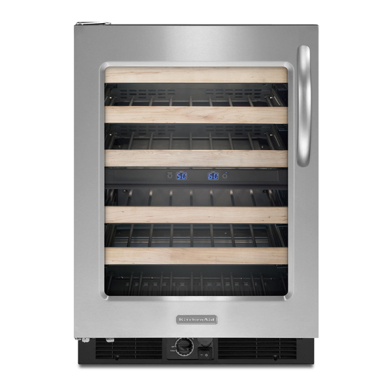
KitchenAid Undercounter Refrigeration Suite
Wine Cellar
Models: KUWS24RSBS
KUWS24LSBS KUWS24RSSS
KUWO24RSBX KUWO24LSBX
Beverage Center
Models: KBCS24RSBS
KBCS24LSBS KBCS24RSSS
KBCO24RSBX KBCO24LSBX
Undercounter Refrigerator
Models: KURS24RSBS
KURS24LSBS KURS24RSSS
KURO24RSBX KURO24LSBX
JOB AID
4317405
Advertisement
Table of Contents

Related Manuals for KitchenAid KUWS24RSBS


Summary of Contents for KitchenAid KUWS24RSBS
- Page 1 KAR-18 TECHNICAL EDUCATION KitchenAid Undercounter Refrigeration Suite Wine Cellar Models: KUWS24RSBS KUWS24LSBS KUWS24RSSS KUWO24RSBX KUWO24LSBX Beverage Center Models: KBCS24RSBS KBCS24LSBS KBCS24RSSS KBCO24RSBX KBCO24LSBX Undercounter Refrigerator Models: KURS24RSBS KURS24LSBS KURS24RSSS KURO24RSBX KURO24LSBX JOB AID 4317405...
- Page 2 FORWARD This KitchenAid Job Aid, “Wine Cellar, Beverage Center & Undercounter Refrigerator” (Part No. xxxxxxx), provides the technician with information on the installation, operation, and service of the Wine Cellar, Beverage Center & Undercounter Refrigerator. For specific information on the model being serviced, refer to the “Use and Care Guide,”...
- Page 3 TABLE OF CONTENTS Page GENERAL ..........................1-1 Wine Cellar, Beverage Center & Refrigerator Safety ............1-1 Model Number Designations .................... 1-2 Serial Number Designations ..................... 1-2 Model & Serial Number Label & Wiring Diagram Locations ..........1-3 Warranty ........................... 1-4 INSTALLATION INFORmATION ....................
- Page 4 TABLE OF CONTENTS - CONTINUED Page Remove the Door ......................4-25 Remove the Door Skin and Handle .................. 4-25 Remove Door Gasket ....................... 4-26 Beverage Center Layout (BC) ..................4-26 Upper Compartment Temperature Display Thermistor Inside Evaporator Cover (BC) ..4-27 Disassemble Separator (UW, BC) ...................
-
Page 5: General
GENERAL WINE CELLAR, BEVERAGE CENTER & REFRIGERATOR SAFETY Your safety and the safety of others are very important. We have provided many important safety messages in this manual and on your appliance. Always read and obey all safety messages. This is the safety alert symbol. This symbol alerts you to potential hazards that can kill or hurt you and others. -
Page 6: Model Number Designations
NUmBER DESIGNATIONS mODEL NUmBER BRAND K = KITCHENAID PRODUCT GROUP UR = UNDERCOUNTER REFRIGERATOR UW = WINE CELLAR BC = BEVERAGE CENTER PRODUCT IDENTIFICATION S = SUPERBA O = OVERLAY MODEL WIDTH 24 = 24” WIDE DOOR SWING R = RIGHTHAND DOOR... -
Page 7: Model & Serial Number Label & Wiring Diagram Locations
mODEL & SERIAL NUmBER LABEL & WIRING DIAGRAm LOCATIONS model & Serial Number Label Location (On Upper Right Side of Liner) Wiring Diagram... -
Page 8: Warranty
If you need service, first see the “Troubleshooting” section of the Use & Care Guide. After checking “Troubleshooting,” additional help can be found by checking the “Assistance or Service” section or by calling KitchenAid. In the U.S.A., call 1-800-422-1230. In Canada, call 1-800-807-6777. -
Page 9: Installation Information
INSTALLATION INFORmATION TOOLS AND PARTS ELECTRICAL REQUIREmENTS Gather the required tools and parts before starting installation. WARNING • Phillips screwdriver LOCATION REQUIREmENTS WARNING Electrical Shock Hazard Disconnect power before servicing. Replace all parts and panels before operating. Failure to do so can result in death or electrical shock. -
Page 10: Unpack The Unit
UNPACK THE UNIT DOOR CLOSING The UW, BC or UR has four leveling legs. If it seems unsteady or you want the door to close more easily, adjust the tilt using the instruc- tions below. • Remove the Packaging. Remove tape and glue residue from surfaces before turning on the unit. -
Page 11: Remove The Base Grille
REmOVE THE BASE GRILLE REPLACE THE BASE GRILLE Open the unit door. Open the unit door. Using a Phillips screwdriver, remove the two screws. Push both tabs in toward the center to release the base grille from the unit. Position the base grille so that both tabs align and the base grille snaps into place. - Page 12 ---- NOTES ----...
-
Page 13: Theory Of Operation
THEORY OF OPERATION GENERAL AmBIENT THERmOSTAT (UW, BC) There are three variations of one core platform available: a wine cellar, a beverage center and an all refrigerator. All units share the same The beverage center and wine cellar have basic cooling system with only slight differenc- a 7 watt liner heater located just under the es in airflow inside the cabinet. - Page 14 ---- NOTES ----...
-
Page 15: Component Access
COmPONENT ACCESS REmOVE THE RACKS (UW, BC) Press the release lever on each side and WARNING slide the rack out of the tracks. Release Lever Electrical Shock Hazard Disconnect power before servicing. Replace all parts and panels before operating. Failure to do so can result in death or electrical shock. -
Page 16: Remove The Tracks (Uw, Bc)
REmOVE THE TRACKS (UW, BC) To remove the tracks, lift the front end of the Lay the tracks in order of removal to assist in track and pull the hooked end out of the slot reassembly. There are two different tracks in the wall. -
Page 17: Remove The Separator (Uw, Bc)
REmOVE THE SEPARATOR (UW, BC) Remove the two screws, one at each side, WARNING that secure the separator to the unit. Right side screw Electrical Shock Hazard Disconnect power before servicing. Replace all parts and panels before operating. Failure to do so can result in death or electrical shock. -
Page 18: Remove The Evaporator Cover
REmOVE THE EVAPORATOR COVER WARNING Electrical Shock Hazard Disconnect power before servicing. Replace all parts and panels before operating. Failure to do so can result in death or electrical shock. To remove the cover completely, disconnect Remove the racks. (See page 4-1) the connectors from the back of the unit. -
Page 19: Remove The Evaporator Fan And Motor
REmOVE THE EVAPORATOR FAN AND mOTOR After removing the wires and bracket, pull the WARNING motor shaft out of the fan blade to remove the motor. Electrical Shock Hazard Disconnect power before servicing. Replace all parts and panels before operating. Failure to do so can result in death or electrical shock. -
Page 20: Remove The Main Thermostat (Uw, Bc)
REmOVE THE mAIN THERmOSTAT (UW, BC) Carefully work the bulb out from behind the WARNING wires and tubing. The thermostat bulb runs down the right side of the evaporator and is protected with an insulated sleeve. Pull the bulb out from beside the evaporator. Take careful note of the positioning of the bulb and insulating sleeve for proper reinstallation, otherwise the thermostat may be adversely... - Page 21 Pull the thermostat bulb through the liner into . Remove the control knob. Remove the the component compartment from the back thermostat control by rotating the back of the of the unit. thermostat up and out of the control box. Remove the base grill.
-
Page 22: Remove The Main Thermostat (Ur)
Pull the thermostat bulb through the liner into REmOVE THE mAIN the component compartment from the back of the unit. THERmOSTAT (UR) WARNING Electrical Shock Hazard Disconnect power before servicing. Replace all parts and panels before operating. Failure to do so can result in death or electrical shock. -
Page 23: Wiring Connector Block
Remove the control knob. Remove the ther- WIRING CONNECTOR mostat control by rotating the back of the thermostat up and out of the control box. BLOCK WARNING Electrical Shock Hazard Disconnect power before servicing. Replace all parts and panels before operating. Failure to do so can result in death or electrical shock. -
Page 24: Remove The Defrost Heater
REmOVE THE DEFROST HEATER Locate the wire ties securing the defrost WARNING heater wires around the evaporator. Cut the two wire ties on the top and two on the right side of the evaporator. Note the location of the wire ties and the routing of the wires for proper replacement during reassembly. -
Page 25: Remove The Defrost Thermostat And Thermal Fuse
REmOVE THE DEFROST THERmOSTAT AND THERmAL FUSE Carefully remove the thermal fuse at the right WARNING side of the evaporator. Wiring connector Electrical Shock Hazard Disconnect power before servicing. Replace all parts and panels before operating. Failure to do so can result in death or electrical shock. -
Page 26: Remove The Evaporator
REmOVE THE EVAPORATOR Remove the evaporator by removing the two WARNING screws that secure the evaporator to the back wall of the unit. (Photo show screws already removed so the brackets could be seen better.) Electrical Shock Hazard Disconnect power before servicing. Replace all parts and panels before operating. -
Page 27: Remove The Base Grille
REmOVE THE BASE GRILLE Remove the base grille. WARNING Components accessible with the base grille removed are: • Condenser • Thermostat control Electrical Shock Hazard Disconnect power before servicing. • Door switch Replace all parts and panels before operating. Failure to do so can result in death or Rocker light switch (not included on the Un- •... -
Page 28: Remove The Door Switch Or The Light Switch
REmOVE THE DOOR SWITCH OR THE LIGHT SWITCH Disconnect the wire connectors attached to WARNING the switch. Electrical Shock Hazard Disconnect power before servicing. Replace all parts and panels before operating. Failure to do so can result in death or electrical shock. -
Page 29: Accessing The Unit Compartment
ACCESSING THE UNIT COmPARTmENT WARNING Remove the seven screws that attach the ac- cess panel to the rear of the unit Components accessible with the component cover removed are: • 1. Defrost Timer Electrical Shock Hazard • 2. Condenser Fan Motor Disconnect power before servicing. -
Page 30: Remove Defrost Timer
REmOVE DEFROST TImER Remove the two screws that secure the de- WARNING frost timer to the mounting plate. Electrical Shock Hazard Disconnect power before servicing. Screws Replace all parts and panels before operating. Failure to do so can result in death or electrical shock. -
Page 31: Unit Compartment Wire Connectors
UNIT COmPARTmENT WIRE CONNECTORS WARNING Electrical Shock Hazard Disconnect power before servicing. Replace all parts and panels before operating. Failure to do so can result in death or electrical shock. White Connector - 3 wire Black Connector - 4 wire Black Connector - 3 wire Black Connector - 3 wire White Connector - 2 wire... -
Page 32: Remove The Relay / Overload & Run Capacitors
REmOVE THE RELAY / OVERLOAD & RUN CAPACITORS Pull the Run capacitor and the Relay / Over- WARNING load off the terminals of the compressor. Electrical Shock Hazard Disconnect power before servicing. Replace all parts and panels before operating. Failure to do so can result in death or electrical shock. -
Page 33: Remove Drain Pan
REmOVE DRAIN PAN Use a small flat blade screwdriver to pry up WARNING the corner of the drain pan to release the re- tainer pin. Be sure to save the retainer pin for reinstallation. Pry up corner Electrical Shock Hazard Disconnect power before servicing. -
Page 34: Remove Condenser Fan
Remove two screws that secure the con- REmOVE CONDENSER FAN denser fan to the bracket and remove the fan. WARNING Electrical Shock Hazard Screws Disconnect power before servicing. Replace all parts and panels before operating. Failure to do so can result in death or electrical shock. -
Page 35: Remove Temperature Display Transformer
Disconnect the two wire connectors from the REmOVE TEmPERATURE temperature display transformer to remove DISPLAY TRANSFORmER WARNING Disconnect Two Wire Connectors Electrical Shock Hazard Disconnect power before servicing. Replace all parts and panels before operating. Failure to do so can result in death or electrical shock. -
Page 36: Remove Compressor
REmOVE COmPRESSOR Access the sealed system and discharge the WARNING refrigerant into an approved recovery sys- tem. Electrical Shock Hazard Disconnect power before servicing. Replace all parts and panels before operating. Failure to do so can result in death or electrical shock. -
Page 37: Ambient Thermostat (Uw, Bc)
REmOVE AmBIENT THERmOSTAT (UW, BC) Push the thermostat bulb back through the WARNING hole in the unit. Thermostat Bulb Hole Electrical Shock Hazard Disconnect power before servicing. Replace all parts and panels before operating. Failure to do so can result in death or electrical shock. -
Page 38: Remove Interior Light Bulb
REmOVE INTERIOR REmOVE DOOR SWITCH LIGHT BULB ACTUATOR (UW, BC) Open the unit door. WARNING Remove the two screws that secure the ac- tuator to the bottom of the door. Electrical Shock Hazard Disconnect power before servicing. Replace all parts and panels before operating. Failure to do so can result in death or electrical shock. -
Page 39: Remove The Door
REmOVE THE DOOR REmOVE THE DOOR SKIN AND HANDLE Remove the three screws that secure the top door hinge to the unit. Remove the door (See page 4-25) Three Screws Remove the four screws at the bottom of the door. Four Screws Lift the door skin off of the inner door. -
Page 40: Remove Door Gasket
BEVERAGE CENTER REmOVE DOOR GASKET LAYOUT (BC) Open the door of the unit. The Beverage Center has 3 separate temper- ature zones for cooling. Starting at one of the corners, carefully pull • The top section with one half glass shelf and the gasket away from the door. -
Page 41: Upper Compartment Temperature Display Thermistor Inside Evaporator Cover (Bc)
UPPER COmPARTmENT TEmPERATURE DISPLAY THERmISTOR INSIDE EVAPORATOR COVER (BC) Remove the evaporator cover (See page The upper compartment thermistor is hang- 4-4) ing on a stud inside the evaporator halves Release the two clips on each side and three clips on the top and bottom. Upper Compartment Thermistor Clip... -
Page 42: Disassemble Separator (Uw, Bc)
DISASSEmBLE SEPARATOR (UW, BC) Open the two halves to access the lower WARNING zone temperature display thermistor. Electrical Shock Hazard Disconnect power before servicing. Replace all parts and panels before operating. Failure to do so can result in death or electrical shock. - Page 43 Pay close attention to the positioning of each thermistor and re-tape them in the same po- sitions during reassembly. (BC) The Beverage Center connector plugs: • A. 2 pin feed wire from the back wall of unit. • B. 3 pin connector for the top thermistor. (This will not be present on the Wine Cellar.) •...
- Page 44 ---- NOTES ---- 4-30...
-
Page 45: Component Testing
COmPONENT TESTING Before testing any of the components, perform • Check all connections before replacing com- the following checks: ponents, looking for broken or loose wires, failed terminals, or wires not pressed into • The most common cause for control failure connectors far enough. -
Page 46: Light Switches
Electrical Shock Hazard Disconnect power before servicing. Replace all parts and panels before operating. Failure to do so can result in death or electrical shock. LIGHT SWITCHES RELAY / OVERLOAD Rocker Light See Page 4-18 for access and removal pro- cedures for the Relay / Overload. -
Page 47: Condenser Fan Motor
Electrical Shock Hazard Disconnect power before servicing. Replace all parts and panels before operating. Failure to do so can result in death or electrical shock. CONDENSER FAN mOTOR TEmPERATURE DISPLAY TRANSFORmER Primary Winding Secondary Winding Connector Connector See Page 4-20 for access and removal pro- See Page 4-21 for access and removal pro- cedures for the condenser fan and motor. -
Page 48: Defrost Timer
Electrical Shock Hazard Disconnect power before servicing. Replace all parts and panels before operating. Failure to do so can result in death or electrical shock. DEFROST TImER COmPRESSOR Common Start See Page 4-22 for access and removal pro- cedures for the compressor. Touch the leads of an ohmmeter to the Com- See Page 4-16 for access and removal pro- mon and Run terminals of the compressor. -
Page 49: Ambient Thermostat (Uw, Bc)
Electrical Shock Hazard Disconnect power before servicing. Replace all parts and panels before operating. Failure to do so can result in death or electrical shock. AmBIENT THERmOSTAT DEFROST BImETAL (UW, BC) See page 4-11 for access and removal pro- cedures for the defrost bimetal. Touch the leads of an ohmmeter to the two terminals of the defrost bimetal. - Page 50 ---- NOTES ----...
-
Page 51: Diagnosis & Troubleshooting
DIAGNOSIS & TROUBLESHOOTING Try the solutions suggested here first in order THERE IS WATER IN THE to avoid the cost of an unnecessary service DEFROST DRAIN PAN call. THE UW, BC, UR WILL • Is the unit defrosting? The water will evapo- rate. -
Page 52: Temperature Is Too Warm
TEmPERATURE IS THE DOOR IS TOO WARm DIFFICULT TO OPEN • Is the door opened often? Be aware that the WARNING unit will warm when this occurs. In order to keep the unit cool, try to get everything you need out of the unit at once, keep wine bot- tles positioned label side up so that they are easy to find, and close the door as soon as the wine is removed. -
Page 53: Wiring Diagrams
WIRING DIAGRAmS WINE CELLAR WIRING DIAGRAm... -
Page 54: Beverage Center Wiring Diagram
BEVERAGE CENTER WIRING DIAGRAm... -
Page 55: Undercounter Refrigerator Wiring Diagram
UNDERCOUNTER REFRIGERATOR WIRING DIAGRAm... - Page 56 ---- NOTES ----...
-
Page 57: Product Specifications
WARRANTY INFORmATION SOURCES IN THE UNITED STATES: FOR PRODUCT SPECIFICATIONS AND WARANTY INFORmATION CALL: FOR WHIRLPOOL PRODUCTS: 1-800-253-1301 FOR KITCHENAID PRODUCTS: 1-800-422-1230 FOR ROPER PRODUCTS: 1-800-447-6737 FOR TECHNICAL ASSISTANCE WHILE AT THE CUSTOmER’S HOmE CALL: THE TECHNICAL ASSISTANCE LINE: 1-800-253-2870...
Need help?
Do you have a question about the KUWS24RSBS and is the answer not in the manual?
Questions and answers