Advertisement
Quick Links
Applicable Models
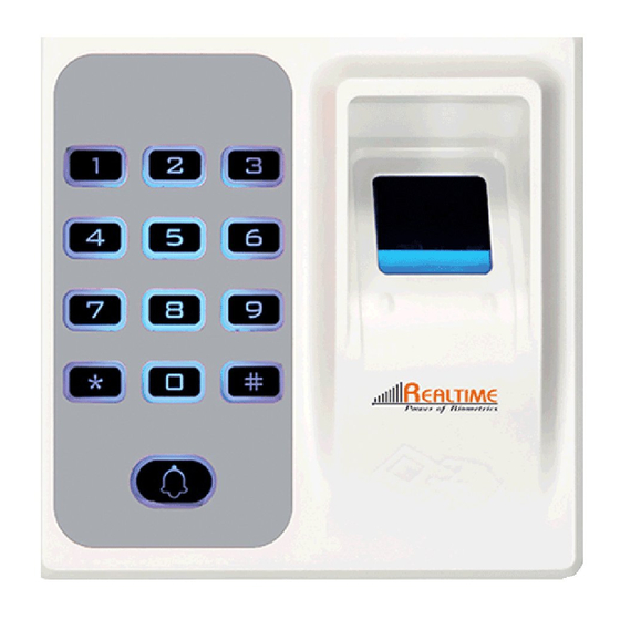
Status light
Fingerprint-reading area
Keypad
Card-reading area
Doorbell
Reset
USB
Fixing hole
-1-
Mounting screws
Power on unlock
outage unlocking
Wiring Schematic Diagram A
III.Ports & Wiring Diagram
Access controller
outage unlocking
Wiring Schematic Diagram B
* power
P1
•
0--+ teams —
12VAlarrn
doorbel"
door ma net
Diagram A instructions is electricity
lock, using a special power supply
access of the connection mode;
Diagram B instructions is electricity
lock and fingerprint access to share
a power supply.
•
Door open button
1 ) Correct method :
Use the finger to evenly
press the center of
fingerprint are
2) Wrong methods:
S
",--5 0 05\15 0 2_
I.Product Overview and Installation Instruction
Fingerprint Access Control System
User Manual
E A LT IME
Power of Biometrics
ry
•
CD CD 0
000
0 ®®
0
CD
0
(g,
CD
S.N.
Functions
1
Dark-background fingerprint reader
2
Built-in card reader
3
User verification with fingerprint or card
4
Numeric keys
5
Tamper alarm
6
Reading head for data output
7
86mm box-type panel for installation
Operating Environment:
Room temperature: -20°C-+50°C
Relative humidity: 95%
Operating Voltage & Current:
Input DC: +12V
Standby current:560mA
Operating current:5120mA
0 Due to continuous update of our products
11.Inputting Fingerprint
Suggested finger: index finger, middle finger or
ring finger instead of thumb or little finger
Not Flat
Not !entered
Tilted
Low position
012V
0 RS485A
0 RS485B
O GND
O ALARM1-
0 Bell-
0 Bell+
0 D Sentor
0 Button
0 Lock NO
0 Lock NC
0 Lock COM
0 GND
0 12V
0 12V
0 GND
0 WG-OUTO
0 WG-OUT1
0 12V
0 RS485A
0 RS485B
0 GND
0 ALARM1-
0 Bell-
() Bell-,
0 D Sentor
0 Button
0 Lock NO
0 Lock NC
0 Lock COM
0 GND
0 12V
0 12V
Advertisement


Need help?
Do you have a question about the TD1D and is the answer not in the manual?
Questions and answers