Table of Contents
Advertisement
Quick Links
Advertisement
Table of Contents

Related Manuals for Goldwing YAK 55M 70 E


Summary of Contents for Goldwing YAK 55M 70 E
- Page 1 ARF® MODEL 60in YAK55M 70 Electric Electric Extreme Series Instruction Manual...
- Page 2 ARF® MODEL Dear Customer, Thanks for purchasing this newly designed 60in YAK55M 70E aerobatic RC airplane. With an approximate flying weight of 5.5 Lbs., the new 60in YAK55M was designed for IMAC and free style flying. It was developed with unique appearance and extreme flight performance in mind. The new 60in YAK55M was covered with genuine Monocote film, and equipped with good quality accessories, including carbon fiber wing tube, carbon fiber landing gear.Also including KUZA Alloy Backplate Hollowed-out Electric Spinner We hope you enjoy this plane as much as we do.
- Page 3 ARF® MODEL Wing Area: 725sq in (46.8sq dm) Flying Weight: 5-6 lbs. (2250-2700g) Electric Power Setup: KUZA EXM4120 KV750 4S 3700-4400mAh, 15x8prop KUZA EXM4120 KV500 6S 3300-3700mAh, 15x8prop DUSKY XM5050EA-9 6S 3300-3700mAh, 15x8prop or other 1100-1300 watt, 300g class electric motors ...
- Page 4 ARF® MODEL Quick release canopy latch Servo extension safety connector clips High performance cap head screws...
- Page 5 ARF® MODEL High quality 2mm ball links assembly New fiberglass horn assembly Light Electric C.F.Tail wheel assembly High-quality durable rubber wheels...
- Page 6 ARF® MODEL Improved new Axle (the material of Axle is stainless steel ) Carbon fiber landing gear Increased diameter carbon fiber wing tube over previous versions Strengthened fuselage by carbon fiber board and rods KUZA Alloy Backplate Hollowed-out Electric Spinner included...
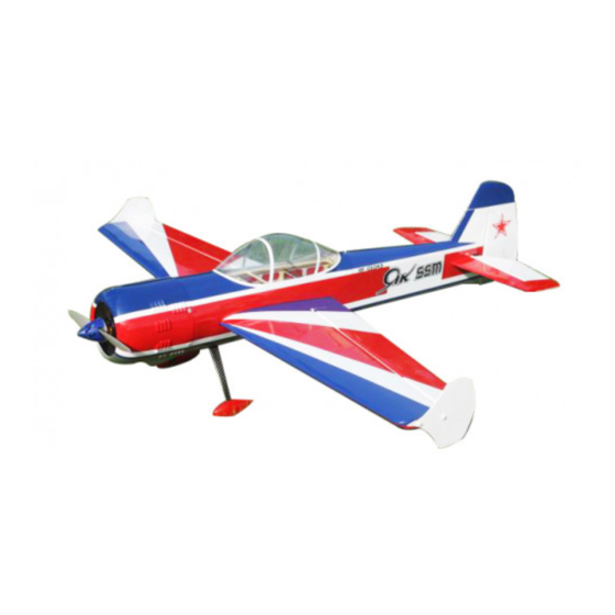
- Page 7 ARF® MODEL Honeycomb Board carton packing for safer transportation Scheme A White/red/blue...
- Page 8 ARF® MODEL Scheme B Yellow/ black/red Items Required to Complete This Model 1000-1200 Watt, 300g class electric motor 70-100A ESC 4 or 5 mini size high torque servos (Hitec HS5245 or HS 7245) *1 or 2 servos for elevators...
- Page 9 ARF® MODEL Appropriate servo arms Servo wire extensions. two 6”, two 12” Appropriate Lipo batteries (6S 2600-3300mah) Receiver of your choice (minimum 4 channels) RC radio of your choice Shop Supplies/Tools Covering Iron and heat gun ...
- Page 10 ARF® MODEL Some modellers prefer to seal the hinge gaps using strips of appropriate covering or clear trim tape. We have found this to be helpful with models intended for higher speed flight or models with unusually large hinge gaps. Aircrafts that utilize a very tight double beveled hinge line and do not normally require this step.
- Page 11 ARF® MODEL Ball links (Bag No. KAG0011): 8 PCS 4 Servo extension safety connector clips (Bag No. KAG0019) Main rubber wheels (Bag No. KAG0146) :2 Pcs...
- Page 12 ARF® MODEL Stainless steel Axle kits (Bag No. KA07NH) C.F Tail wheel assembly (Bag No. KAG0101) Side force generators (mounted with four M3X18 hand bolts and 2 wood sheets) 2.5"(63mm) CNC Alloy Backplate Hollowed-out Spinner (Bag No. KAG0203)
- Page 13 ARF® MODEL 4 (3x16mm) hex-head bolts & Washers for landing gear mounting Screews & Washers for cowl: 4(2.5x12mm) Hexagon socket screws & 4 PTFE Washers Motor mounting hardware set...
- Page 14 ARF® MODEL 3 Hex keys Construction 1. Wing Assembly 1.1 Locate two wing panels with ailerons, and two set of control horns and base plates. 1.2 Locate the slot for control horn on aileron, remove the covering over the slot with heated soldering iron or sharp hobby knife, and make sure you do it on the bottom side of the aileron.
- Page 15 ARF® MODEL 1.4 Fill the slot and coat the root of control horn and the bottom of base plate with 30 minute epoxy, insert the horn into the slot, press it down firmly. Wipe off excessive epoxy with alcohol wipes. Set aside until cured.
- Page 16 ARF® MODEL mounting are laser pre-drilled, it is advisable to apply some thin CA to strengthen them, Install the servos and screw firmly in place. 1.7 Use your radio to set the centers of each servo and then assemble and adjust the length of each control rod, KUZA 1”...
- Page 17 ARF® MODEL 2. Landing Gear Installation Locate the landing gear set 2.2 Bolt the main gear to the bottom of the fuselage using the supplied bolts 2.3 Install the wheel axles to the landing gear and tighten the nylon-insert lock nut. Install one wheel collar onto the axle.
- Page 18 ARF® MODEL 2.4 Fit the wheel pant in place and install using the 2mm hex-head bolts & Washers. Use thread-lock to secure the screws in place. Repeat the above steps for the other main gear. 3. Elevators Assembly...
- Page 19 ARF® MODEL 3.1 Find the control horn slots on bottom side the elevators, use the method described in 1.2-1.4 to install control horns for elevators. 3.2 Elevator horn slot is located on the left side of elevator. Remove covering over the hole for horizontal stabilizer on fuselage.
- Page 20 ARF® MODEL 3.4 After installing the elevator, use supplied balsa pieces to fill gap behind the elevator as shown below 3.5 Locate the slots for elevator servo, remove covering. Connect wire extension to your servos before feeding the wire into fuselage. Install servo with screws supplied by servo manufacturer. 3.6 Use your radio to set the servo center position and install the large control horn onto the servo.
- Page 21 ARF® MODEL 4. Rudder Assembly 4.1 Locate rudder, a control horn and base plate. Rudder is driven by push-rod, servo bay is on the right side of the fuselage. 4.2 Locate the slot for control horn on rudder, remove the covering over the slot with heated soldering iron or sharp hobby knife, and make sure you do it on the right side of the aileron.
- Page 22 ARF® MODEL 4.4 Fill the slot and coat the root of control horn and the bottom of base plate with 30 minute epoxy, insert the horn into the slot, press it down firmly. Wipe off excessive epoxy with alcohol wipes. Set aside until cured. 4.5 Use CA glue to connect hinges for rudder.
- Page 23 ARF® MODEL 4.7 Use your radio to set the center of servo and then assemble and adjust the length of the control rod. The servo arm should be as close to perpendicular to the control rod as possible while the aileron is at neutral.
- Page 24 ARF® MODEL 5.2 Tail wheel kit is pre-assembled in factory, for safety, please remove all screws and then re- assemble with thread locker. 5.3 Drill 2 mm holes on the bottom rear of the fuselage, secure the tailwheel bracket with the provided screws.
- Page 25 ARF® MODEL 6.2 Blind nuts are pre-installed behind the firewall. 6.3 Since the position of cowl is fixed and length of motors vary, you may need to use provided washers and wood crosses to position you motor properly. 7 Cowl Installation 7.1 Test fit the cowl first, make sure it fits well with canopy and fuselage.
- Page 26 ARF® MODEL 7.2 Drill 2mm holes on cowl and fuselage. 7.3 Enlarge the holes on cowl with 2.5mm drill bit. 7.4 Secure the cowl with 2.5X12mm self-threading screws and PTFE washers.
- Page 27 ARF® MODEL 8 Final Radio System Installlation 8.1 Whether you 72 MHz systems or the newer 2.4 GHz systems, proper radio installation and care is vital to the safe and reliable operation of your aircraft. Follow the manufacturer’s instruction for installation guidance of receivers and batteries paying attention to factors such as vibration isolation, adequate cooling, and clearances.
- Page 28 ARF® MODEL input. If the aircraft climbs when inverted then you’ve probably got your CG too far aft. If the nose drops more than slightly, then you are most likely nose heavy. Recommended control surface deflections: Low Rate High Rate Elevator 15 degrees 45-50 degrees Rudder...
- Page 29 ARF® MODEL 10.4 Check all control surfaces for secure hinges by performed a slight tug on the control surfaces and observing if there is any give in the hinges. Check all control rods, ball links, servo screws, etc. for proper operation and installation. 10.5 Check your batteries and perform a proper range check once again with the engine off and running.
- Page 30 ARF® MODEL JR servo arms 26mm/1in for aileron No. KAG0S70F/KAG0S70H/KAG0S70J 32mm/1.25in for elevator & rudder No. KAG0S71F/KAG0S71H/KAG0S71J...
- Page 31 ARF® MODEL * KUZA new Wingbag for 70E Two color to choose: orange/ silver, blue / silver No. KAG0091...
Need help?
Do you have a question about the YAK 55M 70 E and is the answer not in the manual?
Questions and answers