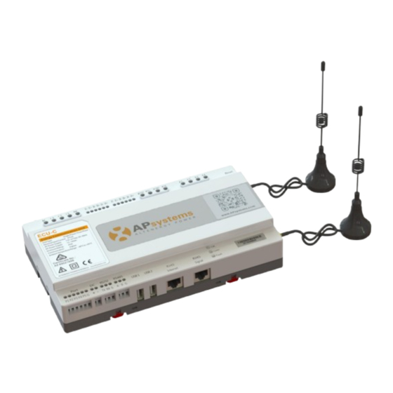
APsystems ECU-C Installation & User Manual
Energy communication unit
with advanced functions
Hide thumbs
Also See for ECU-C:
- Installation and user manual (45 pages) ,
- Installation & user manual (39 pages) ,
- Quick installation manual (35 pages)
Advertisement
Table of Contents
- 1 Important Safety Instructions
- 2 Introduction
- 3 Interface Explanation
- 4 RJ45 Ethernet Network Port
- 5 Hardware Installation
- 6 Cable Connections
- 7 Current Transformer Interface
- 8 Contactor Connection
- 9 Basic Operation
- 10 Local Network Interface
- 11 Real-Time Data Screen
- 12 Remote ECU-C Management (EMA)
- 13 ECU-C Configuration/Ecu-C Status
- 14 Setting the ECU-C Time Zone
- 15 Technical Data
- Download this manual
Advertisement
Table of Contents

Related Manuals for APsystems ECU-C


Summary of Contents for APsystems ECU-C
- Page 1 Installation / User Manual ECU-C Energy communication unit with advanced functions Rev 1.3 rev 1 © All Rights Reserved...
- Page 2 2.6 USB Interface......................5 2.7 Reset .......................... 5 3.Hardware Installation.....................6 3.1 Preparation........................ 6 3.2 Selecting an Installation Location for the ECU-C ............6 3.3 Cable Connections..................... 8 3.4 RJ45 Signal connection ....................8 3.5 Internet Connection ....................8 3.6 Current transformer interface ................. 10 3.7 Contactor connection ....................
-
Page 3: Important Safety Instructions
EMC personnel and is authorized to energize, ground, and tag equipment, systems, and circuits in accordance with established safety procedures. The inverter and system may only be commissioned and operated by qualified personnel. ECU-C Installation/User Manual... -
Page 4: Introduction
The unit collects module performance data from each individual microinverter and transfers this information to an Internet database in real time. Through the APsystems Energy Monitoring and Analysis (EMA) software, the ECU-C gives you precise analysis of each microinverter and module in your solar installation from web-connected device. -
Page 5: Interface Explanation
2.Interface Explanation 2.1 Interface Layout The ECU-C interface includes, (figure 2) from left to right, are AC Input、 Production CT、Consumption CT、Relay Output、RelayFeedback Input、Reset. Additional ports (figure 3) from left to right, arePort、DC、RS232、RS485、USB1、USB2、RJ45、 Internet、RJ45 Signal. AC Input Production CT Consumption CT Relay Output... -
Page 6: Rj45 Ethernet Network Port
The ECU-C allows the user to communicate with the EMA, or log in to the ECU-C's local page in the absence of the wired LAN and WLAN, to set up the system and view the system data via Ethernet network port. -
Page 7: Hardware Installation
Choose a location that is electrically as close to the array as possible. The ECU-C is NOT rated for outdoor use, so if installing outdoors near a junction box or breaker panel, make sure you enclose it in an appropriate weatherproof NEMA electrical box. - Page 8 Do not put the antennas inside a metal box, that will block the signal. Using a Wall Mount When mounting the ECU-C to a wall, make sure to select a cool, dry indoor location. The energy communicator is fixed on the wall with wall screws or anchors.
-
Page 9: Cable Connections
Plug the RJ45 connector in the package to RJ45 Signal port. 3.5 Internet Connection There are three different approaches to connecting the ECU-C to the Internet: Option 1: Direct LAN cable connection. 1) Make sure the LAN cable is connected to the network port on the bottom of the ECU-C. - Page 10 Figure 10 The network cable in the package can be used to connect the ECU-C with PC directly. One side is connected with the ECU-C and the other side is connected with the PC. Then change the IP address and the network mask to 192.168.131.1 and 255.255.255.0, respectively.
-
Page 11: Current Transformer Interface
IA IB IC IA IB IC IA IB IC Figure 11 Please ensure that the ECU-C is in a power off state when installing the transformer. APsystems can provide the current mutual inductors, please contact APsystems or our distributors. ECU-C Installation/User Manual... -
Page 12: Contactor Connection
A3 A4 polarity. Figure 12 ECU-C automatic detection and judgment of the current power grid environment, through the drive signal interface to control the opening or closing of the contactor. The feedback signal interface and NO of contactor are often connected to inform the ECU that the contactor is effectively closed. -
Page 13: Basic Operation
The following diagram shows the connetions on the back of APsystems the ECU-C. RESET Figure 13 To restore the ECU-C’s factory settings, simply press the “Reset” button for three seconds or longer. The unit will automatically return to its default settings. ECU-C Installation/User Manual... -
Page 14: Local Network Interface
Turn on the Wi-Fi function on PC or phone. Scan the ECU ’s SSID which named “ECU-WIFI_XXXX” (the “xxxx” refers to the last 4 numbers of the ECU-C ID), connect to the ECU-C’s SSID. The first connection has no password. - Page 15 ECU-C Eth0 Mac Address Address of ECU-C’s LAN. ECU-C Wlan0 Mac Address Address of the ECU-C’s internal WLAN. Inverter Comm. Signal Level The communication strength between inverters and ECU-C. The range is 1-5, the higher the better. ECU-C Installation/User Manual...
-
Page 16: Real-Time Data Screen
5.3 Real-time Data Screen a) Real Time Data To view the real-time system operation data statistics for your solar array, click “Real Time Data” from the ECU-C home screen to navigate to the real-time data screen. The Real Time Data screen is displayed. - Page 17 5.Local Network Interface The Power generation statistics screen is displayed. Performance data for the Current Week: Figure 18 Performance data for the current month. Figure 19 ECU-C Installation/User Manual...
- Page 18 Figure 20 5.4 Administration Screen a) Managing Inverter IDs The inverter IDs must be programmed into the ECU-C for the ECU-C to recognize the inverters. The ECU-C will NOT auto-sense the inverters. Initial Programming of the ECU-C with the Inverter IDs.
- Page 19 If the number of inverter ID displayed on the page is less than the actual number of inverters installed: 1) Select “Administration” at the top of the page. The ID Management page with the existing inverter IDs is displayed. ECU-C Installation/User Manual...
- Page 20 If the number of inverter IDs displayed on the page is more than the actual number of inverters installed: 1) Select “Administration” at the top of the page. The ID Management page with the existing inverter IDs is displayed. Figure 23 Figure 24 ECU-C Installation/User Manual...
- Page 21 ID from “Input Inverter ID” section, then click “Update”. The message “ID updated successfully!” will be displayed after few seconds. The ID Management page with the existing inverter IDs is displayed: Figure 25 Figure 26 ECU-C Installation/User Manual...
- Page 22 ECU-C and EMA need to be in sync with each other. b) Changing the Date, Time Zone It is critical for accurate power production reporting that the ECU-C is programmed with the correct date, time, and time zone. 1) Select “Administration” at the top of the page.
- Page 23 4) Press “Update”. d) Managing the Network Connection The default network connection setting for the ECU-C is “DHCP,” which allows the ECU-C to automatically establish a connection assignment from the router. The ECU-C can be assigned a static IP Address.
- Page 24 4) Press “Update”. e) Managing the WLAN connection The ECU-C can both work in two modes: WLAN and Local Wireless Access. In WLAN mode, the ECU-C can connect to a router by Wi-Fi. In Local Wireless Access mode, user’s phone or PC can connect to ECU-C to access local web.
- Page 25 5.Local Network Interface Figure 33 Local Wireless Access mode Scan the ECU-C’s SSID on PC and phone, and connect to ECU-C. Enter the ECU-C’s IP 172.30.1.1(The IP is fixed) into browser to access the local web. On the page, you can modify SSID, Channel, Safe Type and Password.
-
Page 26: Remote Ecu-C Management (Ema)
APsystems EMA. 1) Log onto your APsystems EMA account. Your Customer List within the Installer Portal is displayed. 2) Select the customer’s ECU-C you want to manage and click on the username in the "Customer Account" column. Figure 36... -
Page 27: Ecu-C Configuration/Ecu-C Status
IDs. Until the inverter IDs are loaded, the ECU-C will not be able to collect data from the inverters. Update Inverter ID list If an inverter(s) is added or swapped for a new unit, then the ECU-C’s programmed list of inverters will need to be updated. -
Page 28: Setting The Ecu-C Time Zone
6.Remote ECU-C Management (EMA) 6.2 Setting the ECU-C Time Zone 1) Click the remote control menu to enter the remote settings page 2) Select the “ECU-C SETTING” tab. The ECU-C Configuration page is displayed. Time Zone Pull Down Field Figure 38 3) Using the “Time Zone”... - Page 29 6.Remote ECU-C Management (EMA) Operation Selection (Add or Delete) Inverter ID Field Figure 40 Adding Complete List of Inverter IDs for a Newly Installed System There are two different approaches to add the inverter IDs: Option 1: Webpage - 1. Select Add inverter based on registration list 1) Select “Add”...
-
Page 30: Technical Data
Integrated PV production metering (+/- 0.5% via CT) and Meter Accuracy optional consumption monitoring (+/- 2.5% via CT) Compliance IEC/EN61010-1,EN61000-6-2, Compliance EN61000-6-4,2014/53/EU,EN301489-1/-17,EN62311, EN 300328 Specifications subject to change without notice. Please ensure you are using the most recent update found at www.APsystems.com. 2017/09/21 Rev1.3 ECU-C Installation/User Manual... - Page 31 The correct disposal of your old appliance will help prevent potential negative consequences for the environment and human health. For more detailed information about disposal of your old appliance, please contact your city office, waste disposal service or the shop where you purchased the product. ECU-C Installation/User Manual...
- Page 32 Mail: info@altenergy-power.com APsystems America 600 Ericksen Ave NE, Suite 200 Seattle, WA 98110 Tel: 844-666-7035 Mail: info@APsystems.com APsystems Europe Rue des Monts dor ZAC de Folliouses Sud-Les Echets 01700 Miribel, France Tel: +33-481 65 60 40 Mail: emea@APsystems.com ECU-C Installation/User Manual...
Need help?
Do you have a question about the ECU-C and is the answer not in the manual?
Questions and answers