Table of Contents
Advertisement
Buy Now at New England Laser & Transit Click to Purchase
Version 1.0
English
Piper 100/200
User manual
Advertisement
Table of Contents

Summary of Contents for Leica Geosystems Piper 100
- Page 1 Buy Now at New England Laser & Transit Click to Purchase PIPER 100/200 User manual Version 1.0 English...
- Page 2 Congratulations on the purchase of a new Pipe Laser from Leica Geosystems. Product The Piper 100 and 200 are laser tools for pipe laying and other construction applications. They are designed and built with the latest innovations in the laser tool industry. They are easy to set up, simple to operate and highly dependable.
- Page 3 Important paragraphs which must be adhered to in prac- tice as they enable the product to be used in a technically correct and efficient manner. Trademarks • Alignmaster (registered trademark of Leica Geosystems) All trademarks are the property of their respective owners. Piper 100/200...
-
Page 4: Table Of Contents
In this manual Description of the System ............1-1 Basic Operation ...............2-1 Standard Set-up Procedures............3-1 Refraction ................4-1 Accessories ................5-1 Accuracy Adjustment ...............6-1 Checking Line and Grade ............7-1 Troubleshooting...............8-1 Care and Transport ..............9-1 Safety Directions ..............10-1 Technical Data ...............11-1 Index ....................i-1 Piper 100/200... - Page 5 Models There are two models of the Piper pipe laser described in this manual: • Piper 100 - Red beam pipe laser • Piper 200 - Red beam pipe laser with the Alignmaster™ feature. Description of the System Piper 100/200...
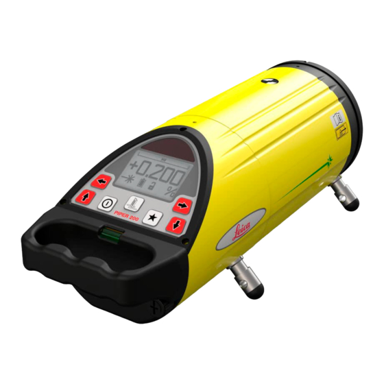
- Page 6 Piper Components a) LCD display b) Switch buttons c) Handle and level vial d) Battery compartment e) Stringline notch Lighted pivot point (top) g) Pivot point (side) h) Self-centering feet Description of the System Piper 100/200...
- Page 7 Case Configuration a) Accessory compartment b) Piper* c) Remote control d) Spare batteries e) Self-centering feet User manual g) Target assembly * Piper shown with optional scope assembly Description of the System Piper 100/200...
-
Page 8: Table Of Contents
Basic Operation Topic Page In this chapter Starting Up ................2-2 The LCD Display..............2-3 The Switch Buttons .............2-3 Three Basic Requirements...........2-4 Entering Grade ..............2-6 Changing Line..............2-7 Line and Grade Lock............2-9 Alignmaster (Piper 200 only)..........2-11 General Procedures............2-13 Basic Operation Piper 100/200... -
Page 9: Piper
Or the Customer Name Screen if it has been programmed by your dealer. e) Finally, the Battery Status Screen will be displayed as a large battery. When the start-up screens are completed, the Main Operating Screen will be displayed and work can begin. Basic Operation Piper 100/200... -
Page 10: The Lcd Display
Left and Right Line Buttons b) Up and Down Grade Button c) Power Button d) Alignmaster Button, Piper 200 only e) Star Button, used in combina- tion with the grade buttons for large grade changes Basic Operation Piper 100/200... -
Page 11: Three Basic Requirements
Procedures in this manual.) You must always define the following three varia- bles in any application. • Grade - The amount of rise or fall over the distance of the pipe to be laid. Set the grade by entering the percent of grade into the Piper display. Basic Operation Piper 100/200... - Page 12 Trivet Mount Assembly. • Line - The position of the laser beam relative to the centerline of the pipe to be laid. Set the line by aligning the laser beam with the next manhole. Basic Operation Piper 100/200...
-
Page 13: Entering Grade
Press both the UP and DOWN arrow buttons (b) at the same time to reset the grade to zero. • Press STAR (c) to exit when desired grade is displayed or wait ten seconds and the screen will automatically return to the main operating screen. Basic Operation Piper 100/200... -
Page 14: Changing Line
The speed at which the line moves will increase as the button in held. • Press both the LEFT and RIGHT arrow buttons (b) at the same time to reset the line to the center position. Basic Operation Piper 100/200... - Page 15 The current line position is indicated at the top of the display. Line Centered Line Position Left or Right of Center Left Line Limit Right Line Limit Basic Operation Piper 100/200...
-
Page 16: Line And Grade Lock
To lock the line position, press and hold the STAR button, then press a LEFT or RIGHT arrow button (b) to lock the line at the current position. To unlock grade or line, repeat the same procedure. Basic Operation Piper 100/200... - Page 17 The current status is indicated at the bottom, center of the display. Grade and Line Unlocked Grade Locked Line Locked Grade and Line Locked Basic Operation Piper 100/200 2-10...
-
Page 18: Alignmaster (Piper 200 Only)
(not blinking). • The beam can now be fine positioned to the center of the target using the LEFT or RIGHT arrow buttons (c) on the laser or the remote control. Basic Operation Piper 100/200 2-11... - Page 19 This is normal. The beam is actually pulsing at a very rapid rate to better control the recognition of the target. Alignmaster is designed to work at distances greater than 10 meters (30 feet). Demonstrations or usage at shorter distances may not find the target. Basic Operation Piper 100/200 2-12...
-
Page 20: General Procedures
General Procedures Topic Page In this chapter 2.9.1 Setting up the Target Assembly........2-14 2.9.2 Setting up the Trivet Assembly and Mounting Bracket ..2-15 2.9.3 Typical Second Day Set-up..........2-17 Basic Operation Piper 100/200 2-13... - Page 21 • Adjust the Target in the pipe until the bubble is centered in the level vial. • Observe the Target. Adjust the pipe so that the laser beam is centered on the cross-hairs. Basic Operation Piper 100/200 2-14...
- Page 22 Set the line. Place the Trivet Assembly so that the Piper is aligned with the pipe to be laid.Turn the knobs on the trivet plate until the bubble is centered in the Piper’s cross-axis level vial. Tighten the brass lock nuts to lock the feet in place. Basic Operation Piper 100/200 2-15...
- Page 23 Set the elevation. Loosen the handle on the mounting bracket. Slide the bracket and laser up or down until the desired elevation is achieved. The slide bracket is made of a special material to ensure smooth movement. Tighten the handle to lock the elevation in place. Basic Operation Piper 100/200 2-16...
- Page 24 Piper 200 - Use the Alignmaster feature. Press the ALIGNMASTER button on the Piper or on the Remote to scan and locate the target. Use the LEFT and RIGHT buttons to fine adjust the beam to the center cross hair of the target. Basic Operation Piper 100/200 2-17...
- Page 25 Topic Page In this chapter Pre-Poured Inverts ..............3-2 Open Trench (Transit) ............3-3 In the Pipe or On Top of the Pipe ........3-5 Open Trench (Stringline) .............3-6 Manhole ................3-8 Drop Manhole ..............3-10 Over the Top ..............3-12 Standard Set-up Procedures Piper 100/200...
- Page 26 200, 225, 250 and 300 mm (8, 9, 10, and 12 inch) pipe. • Set the line. Place the Piper in the invert and adjust the beam so it is in-line with the next manhole. Standard Set-up Procedures Piper 100/200...
- Page 27 Piper is in line with the centerline of the pipe to be laid. • Set the elevation. Move the Piper up or down on the (optional) trivet until the required height is set. (Choose the most convenient method for determining the cut-to-invert distance.) Standard Set-up Procedures Piper 100/200...
- Page 28 (15 feet) in front of the Piper. Look throught the transit and move the beam using the LEFT and RIGHT buttons on the Remote until the beam hits the stake and intersects the transit’s cross- hairs. Standard Set-up Procedures Piper 100/200...
- Page 29 300 mm (8, 9, 10, and 12 inch) pipe. • Set the line. Place the piper in or on the pipe and adjust the beam so that it is in line with the next manhole. Standard Set-up Procedures Piper 100/200...
- Page 30 (optional) trivet until the required height is set. (Choose the most convenient method for determining the cut- to-invert distance.) • Set the line. Locate the line for the laser beam. Standard Set-up Procedures Piper 100/200...
- Page 31 5 meters (15 feet) in front of the Piper. Use the LEFT and RIGHT arrow buttons on the Remote to move the beam until it hits the stake and intersects the stringline. Standard Set-up Procedures Piper 100/200...
- Page 32 Set the elevation. Place the Piper in the manhole. Move the Piper up or down on the (optional) trivet until the required height is set. (Choose the most convenient method for determining the cut- to-invert distance.) Standard Set-up Procedures Piper 100/200...
- Page 33 (15 feet) in front of the Piper. Look throught the transit and move the beam using the LEFT and RIGHT buttons on the Remote until the beam hits the stake and intersects the transit’s cross- hairs. Standard Set-up Procedures Piper 100/200...
- Page 34 Set the elevation. Lower the pre- • assembled Drop Manhole Assembly and Piper into the manhole until the T-bar is approxi- mately 150 to 300 mm (6 to 12 inches) above or below the pipe. Standard Set-up Procedures Piper 100/200 3-10...
- Page 35 T-bar to secure it in the manhole. Move the Piper up or down on the adjustable pole until the beam is approximately at the required elevation. • Set the line. Adjust the beam so that it is in line with the next manhole. Standard Set-up Procedures Piper 100/200 3-11...
- Page 36 Attach the Piper to the tripod and tighten securely. • Set the crosshairs of the scope on a target and then adjust the beam to the target using the LEFT and RIGHT arrow buttons on the Piper or Remote. Standard Set-up Procedures Piper 100/200 3-12...
-
Page 37: Refraction
• In these conditions, Leica Geosystems strongly recommends the use of a blower assembly to reduce or eliminnate the effects of refraction. A blower mixes the different layers of air temperature and density inside a sewer pipe, thereby creating a uniform medium for the laser beam to pass through. - Page 38 Use clamps to attach the blower hose at the beginning of the pipe where the laser is located. Position the end of the hose at a 60° angle to force the air to swirl as it travels through the pipe. • Apply power to the blower and let it operate. Refraction Piper 100/200...
-
Page 39: Accessories
Accessories Topic Page In this chapter Target Assembly..............5-2 Remote Control..............5-3 Trivet Assembly..............5-4 Self-Centering Feet .............5-5 Lithium-Ion Battery .............5-6 Accessories Piper 100/200... - Page 40 MASTER button is pressed, the beam scans from side to side and until it detects the reflective strips then stops between the them. • A small, 100 mm (4 inch) self-centering target (c) is available for these smaller pipes. Accessories Piper 100/200...
- Page 41 Sending LED – The sending LED flashes to indicate that the remote is sending a signal to the Piper. • The Remote is powered by a 9-volt type battery. The battery can only be accessed by removing the four screws and the back cover of the remote. Accessories Piper 100/200...
- Page 42 Knob and Stud – Attaches the post to the base. e) Trivet Base – Large and heavy for better stability. Leveling Foot Assembly (3) – For leveling the Piper and locking in place. g) Mounting Bracket – Attaches to the Piper with the Piper feet. Accessories Piper 100/200...
- Page 43 Optional Self-Centering Feet are also available: • 200 mm (8 inch) Pipe • 225 mm (9 inch) Pipe • 250 mm (10 inch) Pipe • 300 mm (12 inch) Pipe • For 100 mm (4 inch) pipe remove the feet completely. Accessories Piper 100/200...
- Page 44 Lithium-Ion Battery Topic Page In this chapter 5.5.1 Removing the Battery ............5-7 5.5.2 Installing the Battery ............5-8 5.5.3 Charging the Battery ............5-9 Accessories Piper 100/200...
- Page 45 The battery sits in a holder that is part of the handle assembly. Turn the Handle and Battery Assembly upside-down. • Release the small tab (c), and press the battery upwards to remove the battery from the holder. Accessories Piper 100/200...
- Page 46 Turn the Handle and Battery Assembly over and slide the it into the rear of the Piper. The gold contacts (d) should be facing up as shown. • Tighten the two locking screws (a) firmly to ensure a good watertight seal. Accessories Piper 100/200...
- Page 47 Use the Leica Geosystems battery and charger recommended by Leica Geosystems to ensure the correct functionality of the instrument. 5.5.3 Charging the Battery • Follow the instructions received with your charging unit to ensure proper charging of the battery. Primary Use / Charging •...
- Page 48 +10°C to +20°C/+50°F to +68°F if possible. • It is normal for the battery to become warm during charging. Using the chargers recommended by Leica Geosystems, it is not possible to charge the battery if the temperature is too high. Operation / Discharging •...
-
Page 49: Accuracy Adjustment
Do not enter this mode or attempt adjustment unless you plan to change the accuracy. Accuracy adjustment should only be performed by a qualified individual that understands basic adjustment principles. Accuracy Adjustment Piper 100/200... - Page 50 Subtract B1 from A1 to determine C1, and B2 from A2 to determine C2. If C1 and C2 are the same, the Piper is accurately adjusted. If C1 and C2 are not the same, continue with the accuracy adjustment procedure. Accuracy Adjustment Piper 100/200...
- Page 51 100 feet). • The Piper icon will blink to indicate that the unit has not reached the level position. • The LEFT or RIGHT arrow buttons (d) may be used to move the line during this procedure. Accuracy Adjustment Piper 100/200...
- Page 52 Press the STAR Button (e) to accept, save, store the adjustment activity, and return to the main operating screen (f). • Pressing the POWER button at any time before completing the procedure will turn off the unit, and will revert to previous adjustment information. Accuracy Adjustment Piper 100/200...
-
Page 53: Checking Line And Grade
50 feet) of pipe is laid to ensure the pipe is at the proper grade and line. Checking Line and Grade • Set up a transit or automatic level as shown in the illustration. • Take grade readings at the ends of the pipe using a grade rod. Checking Line and Grade Piper 100/200... - Page 54 • If they are not equal, repeat the procedure to ensuure that a mistake was not made. If they are still not equal, check the accuracy of the Piper and the instrument being used. Checking Line and Grade Piper 100/200...
-
Page 55: Troubleshooting
Remove and replace or recharge the battery. The Piper uses an intelligent battery system that indicates the remaining battery charge. This is displayed at power up and at all other times on the main operating screen. Troubleshooting Piper 100/200... - Page 56 STAR, then a line or grade button to unlock. See appropriate section of the manual. Line or grade may have reached its furthest limit. Line limits are indicated by the icon at the top of the display. Grade limits are from -10% to +25% of grade. Troubleshooting Piper 100/200...
- Page 57 The Target, Question Mark and Sun Icon indicates that and Sun Icon the Piper is in too bright of light conditions for the Alignmaster fucntion to find the target. Try shading to reduce the affects of the sun. Troubleshooting Piper 100/200...
- Page 58 Line movement may be locked. • The remote is too far from the Piper to activate the function desired. Move closer and try again. • The Remote’s battery may be low. Replace the battery and try again. Troubleshooting Piper 100/200...
-
Page 59: Care And Transport
Care and Transport Topic Page In this chapter Transport ................9-2 Storage ................9-3 Cleaning and Drying ............9-4 Care and Transport Piper 100/200... - Page 60 Always carry the product in its transport container and secure it. Shipping When transporting the product by rail, air or sea, always use the complete original Leica Geosystems packaging, transport container and cardboard box, or its equivalent, to protect against shock and vibration. Shipping, transport...
-
Page 61: Technical Data
Remove batteries from the product and the charger before storing. • After storage recharge batteries before using. • Protect batteries from damp and wetness. Wet or damp batteries must be dried before storing or use. Care and Transport Piper 100/200... - Page 62 40°C / 108°F and clean them. • Do not repack until everything is completely dry. Cables and Plugs • Keep plugs clean and dry. • Blow away any dirt lodged in the plugs of the connecting cables. Care and Transport Piper 100/200...
-
Page 63: Safety Directions
General................10-2 10.2 Intended Use..............10-3 10.3 Limits of Use ..............10-5 10.4 Responsibilities ..............10-6 10.5 Warranty ................10-7 10.6 Hazards of Use..............10-8 10.7 Laser Classification ............10-13 10.8 Electromagnetic Compatibility (EMC) ......10-18 10.9 FCC Statement, Applicable in U.S........10-20 Safety Directions Piper 100/200 10-1... - Page 64 The following directions should enable the person responsible for the product, and the person who actually uses the equipment, to anticipate and avoid oper- ational hazards. The person responsible for the product must ensure that all users understand these directions and adhere to them. Safety Directions Piper 100/200 10-2...
- Page 65 • Use of products with obviously recognizable damages or defects. • Use with accessories from other manufacturers without the prior explicit approval of Leica Geosystems. • Inadequate safeguards at the surveying site, for example when measuring on roads. Safety Directions...
- Page 66 The product is not to be operated until the user has been instructed on how to work with it. Safety Directions Piper 100/200 10-4...
- Page 67 Danger Local safety authorities and safety experts must be contacted hazardous explosive areas, or in close proximity to electrical situations by the person in charge of the product. Safety Directions Piper 100/200 10-5...
- Page 68 Manufacturer of the Manufacturer of the product Leica Geosystems AG, CH-9435 Heerbrugg, here- product inafter referred to as Leica Geosystems, is responsible for supplying the product, including the user manual and original accessories, in a completely safe condition. Manufacturers of...
- Page 69 10.5 International Warranty International The International Warranty can be downloaded from the Leica Geosystems AG Warranty home page at http://www.leica-geosystems.com/internationalwarranty or received from your Leica Geosystems dealer. Safety Directions Piper 100/200 10-7...
- Page 70 Precautions: Periodically carry out test measurements and perform the field adjustments indicated in the user manual, particularly after the product has been subjected to abnormal use and before and after important measurements. Safety Directions Piper 100/200 10-8...
- Page 71 Precautions: When setting-up the product, make sure that the accessories (e.g. tripod, trivet) are correctly adapted, fitted, secured, and locked in position. Avoid subjecting the product to mechanical stress. Safety Directions Piper 100/200 10-9...
- Page 72 Before transpor- tation or shipping contact your local passenger or freight transport company. Warning Using a battery charger not recommended by Leica Geosystems can destroy the batteries. This can cause fire or explosions. Precautions: Only use chargers recommended by Leica Geosystems to charge the batteries.
- Page 73 Precautions: Make sure that the battery terminals do not come into contact with metallic objects. Safety Directions Piper 100/200 10-11...
- Page 74 Dispose of the product appropriately in accordance with the regulations in force in your country. Always prevent access to the product by unauthorized personnel. Warning Only Leica Geosystems authorized service workshops are entitled to repair these products. Safety Directions Piper 100/200...
- Page 75 Class 2 in the wavelength range from 400 nm to 700 nm. Maximum average radiant power 4.75 mW +/- 5% Pulse duration c.w. Beam divergence 0.1 mrad Safety Directions Piper 100/200 10-13...
- Page 76 Do not aim at areas that are essentially reflective, such as a mirror, or which could emit unwanted reflections.Do not look through or beside the optical sight at prisms or reflecting objects when the laser is switched on. Safety Directions Piper 100/200 10-14...
- Page 77 (hazard distance *) of the area in which the presence and activities of personnel are monitored for reasons of protection from laser radiation. Safety Directions Piper 100/200 10-15...
- Page 78 For a pipe laser of laser class 3R this hazard distance is 662 m / 1252 ft. At this distance, the laser beam rates as Class 1, that means direct intrabeam viewing is not hazardous. Safety Directions Piper 100/200 10-16...
- Page 79 Labeling, Laser Clas- Laser Radiation sification Avoid direct eye exposure Class 3R Laser Product according to IEC 60825-1 (2001-08) ≤ 4.75 mW λ = 620 - 690 nm Laser Aperture a) Laser Beam Safety Directions Piper 100/200 10-17...
- Page 80 Warning Electromagnetic radiation can cause disturbances in other equipment. Although the product meets the strict regulations and standards which are in force in this respect, Leica Geosystems cannot completely exclude the possi- bility that other equipment may be disturbed. Caution...
- Page 81 Disturbances caused by electromagnetic radiation can result in erroneous measurements. Although the product meets the strict regulations and standards whichin this respect, Leica Geosystems cannot completely exclude the possibility product may be disturbed by very intense electromagnetic radiation, near radio trans- mitters, two-way radios or diesel generators.
- Page 82 Increase the separation between the equipment and the receiver. • Connect the equipment into an outlet on a circuit different from that to which the receiver is connected. • Consult the dealer or an experienced radio/TV technician for help. Safety Directions Piper 100/200 10-20...
- Page 83 Warning Changes or modifications not expressly approved by Leica Geosystems for compliance could void the user's authority to operate the equipment. Labelling Piper 100/200 a) This device complies with part 15 of the FCC Rules. Operation is subject to the following...
- Page 84 Technical Data Piper 100/200 Laser Diode 635 nm (red) Laser Output 4.75 mW maximum Level Accuracy* ±1.6 mm at 30 m (±1/16” at 100 ft) Working Range 200 m (650 ft) Grade Range -10% to +25% Self-leveling Range -15% to +30%...
- Page 85 Piper 100/200 Dimensions (diameter x length) 96 mm x 267 mm (3.9” x 10.5”) Weight 2.0 kg (4.4 lbs) Protection against water IPx8 (IEC60529) Remote Control Front up to 150 m (500 ft) Back up to 10 m (35 ft)
-
Page 86: Description Of The System
Entering ..........2-6 Blower ............4-1 Lock ............2-9 Lock Icon ..........2-10 Care and Transport ......... 9-1 Case Configuration ......... 1-3 Hazards of Use ..........10-8 Checking Line and Grade ......... 7-1 Cleaning and Drying ........9-4 Piper 100/200... - Page 87 Setup ............. 3-5 Second Day Set-up ........2-17 Open Trench Servo Limit Icon ..........8-1 Stringline ..........3-6 Standby Icon ..........8-2 Transit ............ 3-3 Starting Up ............. 2-2 Over the Top Switch Buttons ..........2-3 Setup ........... 3-12 Piper 100/200...
- Page 88 Target Assembly ........2-14, 5-2 Technical Data ..........11-1 Temperature Limit Icon ........8-1 Transport ............9-2 Trivet Assembly ..........5-4 Setup ........... 2-15 Troubleshooting ..........8-1 Piper 100/200...
- Page 90 International Standards of Quality Management and Quality Systems (ISO standard 9001) and Environmental Management Systems (ISO stand- ard 14001). Ask your local Leica Geosystems dealer for more information about our TQM program. Leica Geosystems AG Heinrich-Wild-Strasse CH-9435 Heerbrugg...
Need help?
Do you have a question about the Piper 100 and is the answer not in the manual?
Questions and answers