Table of Contents
Advertisement
Service
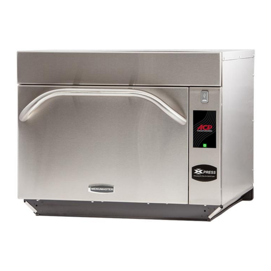
High Speed Combination Oven
Service Manual
This manual is to be used by qualified
service technicians only. ACP, Inc.
does not assume any responsibility for
property damage or personal injury for
improper service procedures done by
an unqualified person.
This Manual covers QT High Speed Combination
Ovens equipped with Touch Screen Controls.
Refer to individual Service Manuals or Technical
Sheets for information on other QT specific
models.
MXP22QTT
16400031
Rev.1
May 2017
Advertisement
Table of Contents

Related Manuals for ACP MXP22QTT


Summary of Contents for ACP MXP22QTT
- Page 1 MXP22QTT High Speed Combination Oven Service Manual This manual is to be used by qualified service technicians only. ACP, Inc. does not assume any responsibility for property damage or personal injury for improper service procedures done by an unqualified person.
- Page 2 Installation………………………………………………………………………………………6 Quick Start Reference Guide .................. 7-12 Firmware Update Procedure………………………………………………………………...13 Care and Cleaning……………………………………………………………………………14 Oven Construction MXP22QTT w/Electronic & w/Mechanical Limiter....15-21 Ceramic Tray and Replaceable Waveguides.............. 22 Teflon Liner Instructions (if equipped)……………………………………………………...23 Component Testing Procedures…………………………………………………………24-25 Interlock Switch Service..................….26 Service Test Mode .
-
Page 3: Important Safety Instructions
IMPORTANT SAFETY INSTRUCTIONS Important Notices for Servicers and Consumers ACP will not be responsible for personal injury or property damage from improper service procedures. Pride and workmanship go into every product to provide our customers with quality products. It is possible, however, that during its lifetime a product may require service. Products... - Page 4 Service Manual. Do not and or any other local government requirements. reach into the equipment area while the unit is The maximum leakage level allowed by ACP energized. Make all connections for the test and is 4mw/cm check them for tightness before plugging the cord into the outlet.
-
Page 5: Save These Instructions
Recognize this symbol as a SAFETY message WARNING When using electrical equipment, basic safety precautions should be followed to reduce the risk of burns, electrical shock, fire, or injury to persons including the following. 1. READ all instructions before using equipment. 9. - Page 6 WARNING WARNING To avoid risk of fire in the oven cavity: Liquids such as water, coffee, or tea are able to be overheated beyond the boiling point without a. DO NOT overcook food. Carefully attend oven appearing to be boiling due to surface tension of the when paper, plastic, or other combustible liquid.
-
Page 7: Specifications
SPECIFICATIONS Power Source Voltage AC 208/230 VAC Amperage (Single Unit) 30 A Frequency 60 Hz Single Phase, 3 wire grounded Receptacle 6-30R Plug 6-30P Power Output – Microwave (IEC705) 2200 Watts Minimum Temperature Rise (∆T) 22°F / 12°C Operating Frequency 2450 MHz Power Consumption 5700 Watts... - Page 8 INSTALLATION STEP 1 - Unpack Oven • Inspect oven for damage such as dents in door or inside oven cavity. • Report any dents or breakage to source of purchase immediately. Do not attempt to use oven if damaged. • Remove all packing materials from oven interior.
- Page 9 QUICK START REFERENCE GUIDE...
- Page 15 After about two minutes the words “Update Complete” will appear and a green “Reboot” button will appear. Do not remove the USB/flash drive. Press the green button. Once the ACP logo and green power button appear, remove the flash drive and press the green power button.
-
Page 16: Care And Cleaning
I. For a new oven, before using it the first time: When oven is clean, spray damp towel with ACP Oven Shield and wipe all interior surfaces. Do not remove Oven Shield Oven Protectant. Turn oven on and pre-heat to start cooking. -
Page 17: Oven Construction
OVEN CONSTRUCTION To remove side panels loosen the three top T-15 torx screws. Remove the three rear T-15 torx screws slide panel to the rear and then down for Door removal. Right Outer Air Filters Panel Top Outer Panel Torx (T-15) Left Outer Panel Outercase Back... - Page 19 HV Transformers Magnetrons Fuses Sensor Triac’s Magnetron TCO’s Convection Heater Element Capacitor / Diodes Small Fuses F2,F3,F4 (12 amp) High Voltage Transformers Temp Sensor F2 - Convection Motor (RTD Convection) F3 - Magnetron # 1 F4 - Magnetron # 2 Switch (Primary) Capacitor...
- Page 20 Circuit Boards Power Relay Limiter (Electronic) Triac Thermocouple (RTD) Temp Sensor (RTD) Cooling Fans Catalytic Converter Convection Motor (Located inside plenum) Convection Motor Main Board *Relay Monitor Board *Power Relay Temp Sensor Snubber (RTD Radiant) Power Supply Board Thermocouple (RTD) (24 VDC) Limiter Triac...
- Page 21 P2004231M w/Mechanical Limiter Cavity Insulation Cavity Steam Vent Insulation Retainer Power Cord HV Board Monitor Relay Board Cook Relay Temp Sensor Power Supply Board Triac (Radiant) Gasket, Per Ft. RESETTABLE Mechanical Limiter...
- Page 22 “Touch” Control Panel Assembly...
- Page 23 Antenna Motor Gear Assembly Antenna Rivet, Plastic Radiant Heater Multi-Wave Spring Washer Flat Washer Lock Nut Note: Requires 15/16” (26mm) Deep Socket See Detail Below *Note: Plastic Rivet cannot be reused. Antenna Motor Rivet, *Plastic Gear Assembly Alignment Arrows Antenna...
- Page 24 CERAMIC TRAY & REMOVEABLE WAVEGUIDE Ceramic Tray - 14080002 Ceramic Tray • Ceramic trays can be replaced without replacing waveguide. Ceramic trays for both waveguides are available as a separate kit which includes (1) ceramic tray and a tube of high temperature sealer with installation instructions.
- Page 25 TEFLON LINERS INSTRUCTIONS Some ovens may be equipped with a PTFE (non-stick) coated liner material to enable easy cleaning of the oven using an approved cleaner. The life expectancy of the liners depends on how much you use your oven. •...
- Page 26 COMPONENT TESTING PROCEDURES Illustration Component Test Results Thermal cutout Disconnect all wires from TCO. Measure resistance across terminals. Control TCO ..........Closed at 235F (113C) and open at 150F (66C) Magnetron TCO ........Open at 300F (149C) and closed at 257F (125C) Diode Discharge Capacitor...
- Page 27 Illustration Component Test Results Transformer Discharge Capacitor Remove all wires from terminals. Measure resistance from: Less than 1 230 to COM..........Less than 1 208 to COM..........230 to Ground ..........Infinite 208 to Ground ..........Infinite Less than 1 Terminal 5 to 6 ..........
- Page 28 INTERLOCK SWITCH SERVICE...
- Page 29 SERVICE TEST MODE The Service Mode is a useful tool to aid in diagnosing any service issue. To access the oven’s service test mode, the PIN Code must be enabled. If the PIN Code is not enabled, enable it (See Below). To determine if the PIN CODE is enabled, press the blue menu icon.
- Page 30 Once the Service Mode is initiated a menu of options and information is displayed. The menu screen can be navigated by swiping up or down if needed. Some components can be activated from this menu – See example of Magnetron 1 (Right Side) below, by touching start to start or stop to stop. Pressing the “back arrow”...
- Page 31 1 and Convection Heater. This circuit is protected by fuse F4 The current amperage being drawn by BOTH Both systems can be started and HV systems. Look for consistent readings Both Magnetrons stopped by pressing the Start or Stop with Convection Heater.
-
Page 32: Error Codes
ERROR CODES Code Description Corrective Action Invalid Display Firmware Update Firmware or Replace Touch Control Touch Screen Error Replace Touch Control Radiant Temp Sensor (RTD)-Open Replace Temp Sensor (Back of Oven) Radiant Temp Sensor (RTD)-Shorted Replace Temp Sensor (Back of Oven) Convect Temp Sensor (RTD)-Open Replace Temp Sensor (Top Left of Oven) Convect Temp Sensor (RTD)-Shorted... -
Page 33: Microwave Power Test
MICROWAVE POWER TEST Power Test All ACP microwave oven power outputs are rated using the IEC705 standards. Using the IEC705 test method requires precision measurements and equipment that is not practical to be performed in the field. Using the test shown below will indicate if the oven performance is satisfactory. - Page 34 SCHEMATICS & DIAGRAMS P2004210M...
- Page 35 P2004210M...
- Page 36 P2004231M...
- Page 37 P2004231M...
- Page 38 NOTES...
- Page 39 16400031 May 2017 NOTES...
Need help?
Do you have a question about the MXP22QTT and is the answer not in the manual?
Questions and answers