Table of Contents
Advertisement
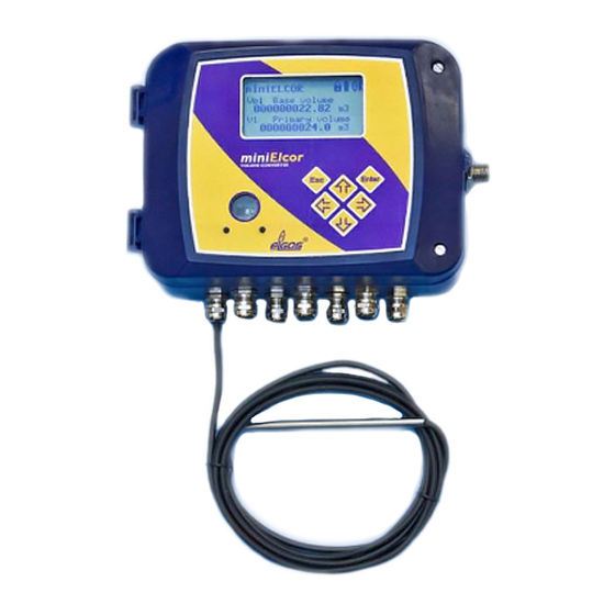
GAS-VOLUME CONVERSION DEVICE
miniELCOR
Device Description
Operation Manual
Technical Description
Mounting instructions
Device settings
Single-channel conversion device of gas volume at measurement conditions to
volume at base conditions. Approved for installation in potentially explosive
atmospheres.
January 2010
PRELIMINARY
Rev. 6g
Advertisement
Table of Contents

Related Manuals for Elgas miniELCOR SCR1

Summary of Contents for Elgas miniELCOR SCR1
- Page 1 GAS-VOLUME CONVERSION DEVICE miniELCOR Device Description Operation Manual Technical Description Mounting instructions Device settings Single-channel conversion device of gas volume at measurement conditions to volume at base conditions. Approved for installation in potentially explosive atmospheres. January 2010 PRELIMINARY Rev. 6g...
- Page 2 Safety Measures This measurement device can be operated only by an operator trained in compliance with the technical terms, safety regulations, and standards. It is necessary to consider any other legal and safety regulations stipulated for special applications. Similar measures also apply for special applications. Similar measures also apply for using the accessories.
- Page 3 TABLE OF CONTENTS Introduction ..................... 1 Basic device description .................. 1 Function principle .................... 2 Device dimensions .................... 7 Device technical description .............. 7 Device architecture .................... 7 Device power supply ..................... 8 Security marks ..................... 11 Product label ....................... 13 Safety instructions ................... 1 4 ...
- Page 4 Securing the device against a change of metrology parameters ...... 38 Putting in operation ................ 4 4 Device operation .................. 4 5 Keypad ........................ 45 Menu system ....................... 46 Main menu ...................... 49 Instantaneous values menu ................. 50 Stored values menu ..................... 50 Device parameters menu .................. 51 ...
- Page 5 15.6 Setting of external power supply failure ............. 1 00 15.7 Setting of communication through MODBUS protocol ........ 1 01 Pressure and temperature sensor/transducer replacement .... 1 05 16.1 Pressure and temperature sensor/transducer replacement procedure in miniELCOR device .................... 1 05 16.2 Software settings of device for proper communication with new temperature sensor ......................... 1 05 16.3 Software settings of device for proper communication with new pressure transducer ...................... ...
- Page 6 miniELCOR Used symbols and definitions Symbol Meaning Unit AGA8-G1 ... Calculation method of gas compressibility factor AGA8-G2 ... Calculation method of gas compressibility factor AGA8-92DC ... Calculation method of gas compressibility factor AGA NX-19 mod ... Calculation method of gas compressibility factor ...
- Page 7 miniELCOR ... Flowrate at measurement conditions ( further primary flowrate) ... Flowrate at base conditions ... Absolute temperature at measurement conditions (T = t + 273.15) ... Gas temperature °C ... Absolute temperature at base conditions ... Volume V or V ...
-
Page 8: Introduction
Device with FW version 4.xx and higher is suitable for connection via encoder NAMUR or SCR. If applied encoder SCR the only miniELCOR SCR1 variant is allowed. The binary inputs can work as check inputs to check the connection with a gas meter or can have a different function, e.g. -
Page 9: Function Principle
miniELCOR For communication with its superior system, the device has a serial interface RS-232 and RS-485. Various communication protocols installed in the device allow easier connection to the SCADA systems. The device cooperates with common phone, radio, GSM, and GPRS modems, and in case of an alarm condition, it can initiate the connection. - Page 10 miniELCOR Volume at measuring conditions (operational volume): Ratio of compressibility factor: Conversion factor: (t + 273.15) Volume at base conditions (standardized volume): = V * C Gas compressibility factor expresses the deviation of properties of natural gas from the properties of an ideal gas. By setting the parameters, it is possible to choose a specific method for calculation of the compressibility factor pursuant to the standard (AGA NX-19 mod, AGA8-G1, AGA8-G2, SGERG-88 or AGA8-92DC).
- Page 11 miniELCOR 1.2.3 Volume correction at measurement conditions Device enables to compensate gasmeter error according to predefined correction curve from gasmeter test certificate. This function and parameters V be activated only by manufacturer or by Acreditive service to ensure that used gasmeter correction curve in dependance on flowrate Q is valid within working conditions.
- Page 12 miniELCOR Combustion heat H To get correct conversion it is necessary to enter correct value of combustion heat and relative conditions. Then device will make new conversion of relative temperature for defined relative conditions and final value will be used for energy calculation.
- Page 13 miniELCOR Fig. 1 Volume and energy calculations - Scheme...
-
Page 14: Device Dimensions
miniELCOR Device dimensions Fig. 2 Device dimensions 2 Device technical description Device architecture The device’s electronics are laid out on three basic boards. The bottom part of the casing contains the board of inputs and outputs containing the battery and back-up battery and terminal box for connecting the pressure and temperature sensors and any device inputs and outputs. -
Page 15: Device Power Supply
miniELCOR The lid of the housing contains a processor board which is protected by a cover and secured by an official mark. The board cover has an opening for access to the service switch. The service switch can be use to enable/disable the setting of the device parameters using a service SW. -
Page 16: Communication With Device 2
miniELCOR Defined mode with life cycle of the supply battery of more than 5 years: • Archiving period of the data archive 1 hr • Communication with device 2 min/day • Showing on the display 2 min/day • Period of input impulses ≤10 Hz •... -
Page 17: External Power Supply
miniELCOR Defined mode for life cycle of back-up battery of 10 years • Storing, temperature 25 °C • Backed-up inputs (DI1 – DI4) not connected or connected contacts disconnected • Does not depend on the presence of the supply battery Defined mode for life cycle of back-up battery of 4 years •... -
Page 18: Security Marks
miniELCOR Fig. 4 Examples of external power supply Security marks Security marks located on the device indicate the technical condition of the device regarding unauthorized handling. Security mark of the manufacturer (metrology mark) - its design is stipulated by the Approval certificate on the quality management system for production, output control, and testing pursuant to Enclosure no. - Page 19 miniELCOR Fig. 5 Security marks (device without SCR encoder) Fig. 6 Security marks of miniELCOR SCR...
-
Page 20: Product Label
miniELCOR Product label Fig. 7 Product label English version Fig. 8 Product label – original certification for ZONE 1... -
Page 21: Safety Instructions 1
miniELCOR 3 Safety instructions General The device has been approved pursuant to the guideline 94/9/CE and an EC certificate on type verification (ATEX) has been issued for it’s use in potentially explosive atmospheres. Respecting this guideline is included in the CE compliance notation. -
Page 22: Special Conditions Of Use
miniELCOR • At hazardous zones device must not be installed at places where outer conditions could create an electrostatic charge. • Device may be cleaned by humid wiper. Special conditions of use 1. The device must not be installed and located in an environment with a potential danger of electrostatic charge of the device casing (e.g. -
Page 23: Metrology Characteristics 1
miniELCOR 4 Metrology characteristics Measuring temperature This device uses the PT1000 temperature sensor to measure temperature. The temperature sensor’s connection is two-wired. The influence of the length and the characteristics of the cable used are considered during calibration and therefore do not influence the accuracy of the temperature measuring. -
Page 24: Compressibility Calculation
miniELCOR Compressibility calculation 4.3.1 PTZ, TZ conversion The compressibility factor is calculated from the composition of the gas listed in the parameters, using one of the following methods implemented in the device: AGA NX-19-mod, SGERG-88, AGA8-G1, AGA8-G2 or AGA8-92DC. Calculation of the compressible factor is performed in each measuring period. In the SGERG-88 and AGA8-G1 methods the value of the heat of combustion is entered for the combustion temperature 25°C / gas temperature 0°C. -
Page 25: Volume Measuring And Calculation
miniELCOR Volume measuring and calculation For measuremet and volume calculation there are used following counters for each channel.: Primary volume counter Corrected volume counter (volume corrected based on gasmeter correction curve) Volume V or V Counter of the operational volume at error conditions (error operational volume) Counter of volume at base conditions (standardized volume) Counter of standardized volume at error conditions... - Page 26 miniELCOR Fig. 9 Storing impulses in counters If a default compressibility is used during the calculation for the reason of deviation of accuracy for the set calculation standard outside the allowed value (see article 4.3.1), whereas p or t are not outside the measuring range, the converted volume is stored in the error counter.
- Page 27 miniELCOR After returning back to correct direction counting will get blocked out into apropriate counters (V ) only after reaching level of primary volume where reversed flow was started up. Primary volume counter is equivalent to gasmeter counter all the time. Fig.
-
Page 28: Inputs
miniELCOR 5 Connecting inputs and outputs Inputs A total of 4 digital inputs marked as DI1 to DI4 can be connected to the device. The inputs are brought out at the terminal board inside the device. The digital inputs can be adjusted using the service SW as a binary or as a LF impulse. The DI1 and DI2 can also be set as HF impulse or binary type NAMUR. - Page 29 miniELCOR but it does not ensure the counting of the impulses. The terminals for the HF NAMUR inputs are marked HF+ and HF- (see Fig. 12). Changing measuring units, setting the gas meter constant The impulse inputs measuring units and the gas meter constant can be adjusted using the service SW.
- Page 30 miniELCOR If SCR encoder is used at battery regime at standard 30s measurement period battery life will be decreased down to 2 years. 5.1.3.3 Device specification with encoder Data from encoder are transferred into EVC via shielded two wires cable. Together with absolute value of gasmeter counter there are transferred other additional data like S/N , gasmeter constant, number of figures nine for counter overturning).
- Page 31 miniELCOR Manual setup of primary volume counter V is not allowed at encoder input.. Installation and replacement of gasmeter Actual counter of gasmeter is transferred into EVC after connection of encoder and EVC possibly causing big difference at primary volume Vm. To prevent against affection of base volume Vb (Vbs) it is necessary to keep following instruction: 1.
-
Page 32: Outputs
miniELCOR Fig. 12 Inputs and outputs terminals Outputs The device has 4 digital outputs DO1 to DO4 which can be configured as binary, impulse, or data. A data output serves for the realization of an analog output 4-20 mA using the CL-1 module which is connected to this output. The outputs can be controlled by the device using the calculation equations entered by the user in the device parameters (for example, it is possible to generate outputs according to the volume of the gas flown through, indication of alarm... -
Page 33: Adding Of Another Pressure Or Temperature Transducer
miniELCOR Using the calculation equations, the value of the output can be parameterized as proportional to pressure, flow, daily consumption, etc. The CL-1 module must be connected to the converter via a safety barrier (DATCOM-K3). Fig. 13 Example of an impulse (binary) output and current output scheme Adding of another pressure or temperature transducer Beyond standardly mounted pressure and temperature transmitters which are... - Page 34 miniELCOR protocol. On account of intrisic safety must be connected transducer intrinsically safe - “ia” type. Type of the transducer is necessary to specify in time of order. For connection of additional digital transducer (EDT 23, EDT 34) must be volume corrector equipped with expansion RS-485 module (KP 065 08) (see Fig.
- Page 35 miniELCOR Fig. 14 Connecting of digital transducer with expansion module RS-485 Fig. 15 Placing of expansion module RS-485 in the device...
-
Page 36: Rs‐232 And Rs‐485 Interfaces
The service SW [22] solely uses this protocol – in case it is necessary to switch to other link level, the ELGAS ver.2 protocol is only wrapped in one other link level (a so called “a tunnel”). The ELGAS ver.2 protocol is used as the only one for loading firmware (protected by the... - Page 37 miniELCOR Communication with GSM and GPRS modems For the purpose of diagnostics during the modem installation, the device has the option of displaying the information from the modem on the presence and connection to a GSM network, and furthermore information on the signal strength measured by the modem.
-
Page 38: Optical Interface Iec‐1107
miniELCOR MTL 5051 setting Switches meaning SW1a ‐‐‐ other modes SW1b ‐‐‐ 5V output SW2a RS232 RS422 output interface SW2b RS422 RS232 output interface Note: Communication output from MTL5051 can be RS-232 or RS-422 Fig. 17 Safety separation of RS-232 communication via separator MTL 5051 Fig. 18 Communication cable wiring Optical interface IEC-1107 On the front face of the casing, next to the keyboard, is an optical window for communication using an optical head. - Page 39 miniELCOR from the economy mode to the mode in which it is able to accept data. It remains in this mode for 180 s from the last communication (timeout) or until the user takes the optical head of the communication interface. Warning: After applying the head, the communication channel from the RS-232/RS-485 device to the optical interface.
-
Page 40: Measurand Marking
miniELCOR 7 Description of function The options of the device regarding displaying the data on the display and storing the quantities are extremely variable and customizable. The user has full control over which quantities will be displayed in the instantaneous values and also which quantities will be stored in the individual archives. -
Page 41: Archives
miniELCOR • Error operational volume Vms • Standardized volume Vb • Error standardized volume Vbs • Flow Qm • Standardized flow Qb • Conversion factor C • Compressibility ratio K • Device error • External power supply presence • Battery capacity •... - Page 42 miniELCOR Standardized volume – absolute condition Error operational volume – absolute condition Error standardized volume – absolute condition Max. daily consumption – operational volume Max. daily consumption – standardized volume Max. hourly consumption – operational volume Max. hourly consumption – standardized volume Internal counter –...
- Page 43 miniELCOR The record with date 01.06 thus means statistical values of quantities in interval 1.05. 6:00 to 1.06. 6:00. 7.3.2 Daily archive Archive capacity: 400 records Has similar features to the monthly archive (for the list of options see Table 3); even here can be stored statistical values of gas consumptions and analog quantities.
-
Page 44: Device Parameterization
miniELCOR 7.3.7 Settings archive Archive capacity: An average of 500 records (depends on length/type of records) The settings archive stores changes of parameters, especially if they have effect on metrological features of the device. The archive also stores the identification of the employee who performed the change. -
Page 45: Other Device Functions
miniELCOR • Gas composition (individual components of the gas pursuant to the set calculation method) • Date and time in the device • volume parameters like setup of gasmeter constant, Vm, Vms, Vb, Vbs, S/N of gasmeter Settings description is in the Art. 9.7. 7.5 Other device functions 7.5.1 Summer/winter time (DST) (*) In device summer/winter time exchange function is implemented which can be... - Page 46 miniELCOR 7.6.1 Switch protection There are two switches located inside the device – the metrology switch and the service switch. 7.6.1.1 Metrology switch - protects the metrology settings of the device. It is located on the inside of the casing cover (see Fig. 3) and protected by a label which is secured by a manufacturer’s security mark (official metrology mark) –...
- Page 47 miniELCOR It is possible to write parameters in the device (i.e. the same as in case of a complete meaning). Table 4 Service switch settings 7.6.2 Access passwords The device works with two passwords: “Password for a complete access” and “Password for reading”.
- Page 48 miniELCOR User level Position of Allowing activity when using Activity the service passwords switch • Reading the instantaneous Allowed when passwords turned off, values of quantities OFF, ON Reading archives • With passwords turned on allowed Reading parameters after entering the “password for reading”...
- Page 49 miniELCOR Assigning the influence of the service switch on entry of parameters Setting the V and Vs counters Change of calculation method of compressibility factor Gas composition setting Setting measuring units and constants Setting default values of temperature and pressure for conversion Table 5 User access level (for “complete”...
- Page 50 miniELCOR...
- Page 51 miniELCOR 8 Putting in operation Device is delivered either in operation condition with connected battery or switched out with disconnected battery. Device is delivered in switched-out position ( no displayed information after pushing of any button) and battery is placed at battery holder. There is placed blocking foil strip between battery and holder contact.
-
Page 52: Keypad
miniELCOR 9 Device operation The device is not equipped with a power switch; if a supply battery is inserted in the device, the device is automatically on (the device also registers LF pulses if the battery is taken out). A 6-button keypad serves for the operation of the device and displaying the measured and other values. -
Page 53: Menu System
miniELCOR • Allows transition in menu to a lower level • When displaying the instantaneous values, Enter causes scrolling through the screen for gradual display of all quantities • Transition from a submenu item to a menu of higher level for version FW 2.XX: •... - Page 54 miniELCOR Service switch Service switch is in OFF position condition Service switch is in ON position Battery Battery is charged 100 % condition Battery is charged 50 % Battery is charged 25 % Device condition Device works flawlessly (sum state – see There is an error in the device art.
- Page 55 miniELCOR Fig. 22 Basic navigation from the initial screen (FW 2.xx)
-
Page 56: Main Menu
miniELCOR Main menu The selected menu item is displayed inversely on the display. Fig. 23 Device main menu and first submenu level... -
Page 57: Instantaneous Values Menu
miniELCOR Instantaneous values menu After pressing the button , the instantaneous values are displayed directly on the display. You can scroll through the data on the display using the up and down arrow buttons. Fig. 24 Example of displaying the instantaneous values Stored values menu For the data, daily, monthly, and binary archives, the method of displaying the data is identical and obvious from the following picture. -
Page 58: Device Parameters Menu
miniELCOR The binary archive is displayed in the same way, with the only difference that the records are not stored in the archive with an archiving period, but in times when the status of one of the stored quantities changed. You can quit viewing the archive by pressing the key Device parameters menu The Communication menu displays the values of the following parameters:... -
Page 59: Parameter Settings Menu
miniELCOR The Input parameters menu displays the following data: • Measuring pressure p - pressure range - serial no. of the pressure converter • Measuring temperature t - measuring range - serial no. of the temperature sensor • Impulse input V - input clamps indication - gas meter constant kp [imp/m3] - gas meter serial no. -
Page 60: System Data Menu
miniELCOR Billing archive Binary archive Extreme archive Save Saving of parameters in to device parameters You must set the parameter you want to edit to the first line of the display using the buttons (parameter is displayed inversely). Initiate editing by pressing Enter. -
Page 61: Diagnostics Menu
miniELCOR A warning is displayed on the display during the test. The indicated errors are marked with prefix “E” and identification number; in case of a warning message the “W” prefix is used. For a complete list of errors and warning messages see par. 9.9. Device reset After choosing a device reset, the software jumps to the starting address and performs a repeated initialization of the entire measuring system. - Page 62 miniELCOR The short form of the summary diagnostics is displayed in the right corner of the highest menu level in the form of abbreviations OK, Err or Wrn (see par. 9.2). This is abbreviated for a summary of the individual statuses; the abbreviation with the highest priority is always displayed.
- Page 63 miniELCOR On the display Description W0 sensor warn. One of the connected converters has activated a warning message. More details can be found by reading out the converters parameters. (FW 2.xx: W1 bat.capacity low) - unused - - unused - W3 overcur.
-
Page 64: Mounting Instructions 5
miniELCOR 10 Mounting instructions Gas volume conversion device miniElcor is compact device inbuilt in sturdy housing made from plastic and it is corresponding with IP66 protection. Device is designed for mounting in hazardous area Zone 1 and Zone 2. Inside the housing there is next to the completely covered evaluation electronics also placed battery and analog pressure transducer with input thread M12x1.5 according to DIN W 3861 for attachment of pressure piping. - Page 65 miniELCOR Fig. 26 Mounting of miniElcor to the mounting plate Fig. 27 Mounting on the pipeline...
- Page 66 miniELCOR Pressure transducer connection For connection of pressure input we recommend to use accurate weldless stainless steel pipe 6x1mm. For connection from the gas pipeline will be used gas meter output Pm (previous Pr) eventually it is neccessary to use welded-on piece dedicated for connection of gas pipe with required size.
- Page 67 miniELCOR User mark Fig. 28 Temperature sensor mounting Temperature sensor Safety nut Thermowell Direct weldolet Fig. 29 Temperature sensor mounting by the help of direct weldolet...
-
Page 68: Cable Connection, Grounding
miniELCOR 10.2 Cable connection, grounding For interconnecting with another devices there it is necessary to use only shielded cables. On device side shielding of the cable must be attached with metal body of cable gland (according to Fig. 30). All cable glands of the device are connected reciprocally. - Page 69 miniELCOR Fig. 30 Shielding connection in bushing...
-
Page 70: Accessories 6
miniELCOR 11 Accessories 11.1 Assembly accessories 1 pc assembly board (metal) 2 pcs stirrup with splice for assembly of board on pipes (for pipes Ø 50 mm, Ø 100 mm, Ø 150 mm – must be specified when ordered) 1 pc temperature well (length 54 mm, 100 mm, 160 mm – must be specified when ordered) 1 pc of welded-on piece for the temperature well (direct or slant –... -
Page 71: Technical Parameters 6
miniELCOR 12 Technical parameters Mechanical parameters - mechanical dimensions (w x h x d) … 193 x 160 x 73 - weight … 1.2 kg - casing material … polycarbonate - terminals – conductor cross section … 0.5 mm – 1.5 mm - mechanical class - electromagnetic environment Environment... - Page 72 miniELCOR - type approval mark … TCM 143/06 – 4664 (in accordance certification under MID) Relative error (within scope of working temperatures) - max. total error of the converter … < 0,5 % of the measured value < 0,3 % of the range …...
- Page 73 miniELCOR ∅ - Connecting pressure … tube 6 mm, screwing ERMETO M12 x 1.5 - design … Internal External, standard cable length 2.5 m max. 5 Measuring temperature - Number of inputs … 1 - Sensor … Pt 1000, platinum resistor detector ÷...
- Page 74 miniELCOR … Terminals DI1 (HF+/-), DI2 (HF+/-) Binary input - NAMUR - Max. number of inputs … 2 - input type … NAMUR (DIN 19234) - min. length of pulse / pause … 200 ms - open circuit voltage … U - Internal resistance …...
- Page 75 miniELCOR DO1, DO2, DO3, DO4 *) terminals Analog output - Max. number of outputs … 4 - Output type … Current output 4-20 mA (realized by moduls CL-1) Connection of external transducer via expanding module RS-485 – optional (communication line RS-485 internal bus) Expanding module marking …...
- Page 76 miniELCOR Binary Impulse Data output output output*) *) necessary to connect an external module CL-1 using the JB separator (e.g. Datcom-K3)
- Page 77 miniELCOR 13 Inexplosiveness parameters HF inputs NAMUR DI1, DI2: HF+, HF- (INPUTS) Terminals Uo = 10V Io = 11mA Po = 27mW 2,8μF 18μF 200mH 700mH LF inputs and binary inputs DI1, DI2, DI3, and DI4: LF+/-, DI3+/-, DI4+/- (INPUTS) terminals Uo = 6.5V Io = 8mA...
- Page 78 miniELCOR Li = 0 RS232 communication line – communication with superior system: Terminals GND1,CTS, TXD, RXD Ui = 20V ΣPi = 0.33W* (sum of outputs in RS485 and RS232) Ci = 200nF Li = 0 MTL5051 (only terminals 1,2,5,6) * Note: Sum of outputs is defined jointly for both interfaces, i.e. sum of outputs on RS485 and RS232 must not exceed 0.33W except MTL5051.
-
Page 79: Standard Device Control After Installation
miniELCOR 14 Device setting After assembly and connection of the device in the measuring place is necessary to set several device parameters (gas meter serial number, gas meter constant and station identification, etc.). Setting of the device is made with help of service SW. -
Page 80: Device Connection With Pc
Communication speed, interface RS232/RS485 38 400 Bd Communication speed, optical interface of infra red head 9 600 Bd Communication protocol ELGAS (ver. 2) Communication address of device (see further) Address1=0 Address2=0 14.3 Setting of communication between device and PC When is device connected with PC, then it is possible to start-up service SW with double-click on its „exe file“. - Page 81 Protocol – Choose the same which is set in the device. For establishing of first communication is in the device set communication protocol ELGAS (ver.2) Fig. 31 Consumption place setting Note for parameters Addr.1, Addr.2:...
- Page 82 miniELCOR If are all data in the line set in right way, then is consumption place set and communication way between PC and device is ready. The user may test communication with help of actual values reading (menu choice Readout -> Actual values).
- Page 83 miniELCOR Fig. 32 Adding of new communication channel After complete definition of new communication channel is a new setting saved with pressing the button OK. New defined channel may be chosen by setting of consumption places setting (see paragraph 14.3.1). 14.3.3 Control and setting of system time In the device are real time clock with calendar.
- Page 84 miniELCOR Fig. 33 Base device parameters Fig. 34 Data archive...
- Page 85 miniELCOR b) Full mode display All parameters are displayed at tree order. This type of display is determined for advanced users. Fig. 35 Base parameters – Full mode display In base display is possible to set followings: a) System parameters – allows identification settings, communication settings, service parameters setting and setting of parameters for conversion.
- Page 86 miniELCOR 14.3.5 Device parametrization with assistant For better device parametrization is in the device users-friendly and simple assistant. User may start up this assistant with click on the icon in the toolbar (see Fig. 36). With selection of Installation of telemetric system in Wizard for editing of parameters start base device parameters setting.
- Page 87 miniELCOR Value range of parameter Address1 is form 0 to 65535, for Address2 is from 0 to 255. For MODBUS protocol is range of parameter Address1 limited from 1 to 247; Adresa2 is not used. After pressing the button Next will be displayed following screen, which is determined for setting of Gas composition.
- Page 88 miniELCOR Setting of default compressibility constant is set in the line C01 Convers. factor C1 and is marked Default const. compressibility. This compressibility value is used in calculation only if there is no compressibility calculated according to mathematical methods. Fig. 39 Cahnnel setting With pressing the button Next follows analogous screen Setting 2.
- Page 89 miniELCOR device parameters (Fig. 40 – simply parameters display) choose Actual value and in the column Value write required data. Fig. 40 Primary volume counter setting It is possible to make complementary setting of binary inputs, outputs and limit values of measured quantities. If you switch over the service switch into position „Off“...
- Page 90 miniELCOR „Init. sum. stat.“ – serves for initialization (clearing) of summary status. b) In SW on PC (Fig. 41) Menu choice „Setup -> Diagnostics (status) of the device -> From device“ will be read out from connected device summary status and status after last device test.
-
Page 91: Password In The Device
miniELCOR 14.3.8 Archives clearing This operation may be made only with help of service SW. Choice in menu (see Fig. 42 ) is possible to clear archives selectively or all archives with one order (except Setup archive). Warning: Deleted data in archives cannot be refreshed. Fig. - Page 92 miniELCOR With password for reading is possible to readout data from the device. Password for full access allows to readout data and writes data into device. Password for full access merges both rights of passwords for reading and for full access. Service SW remember password till its restart, so it is not necessary to enter the passwords again during reading or writing.
-
Page 93: Configuration Examples 8
miniELCOR 15 Configuration examples In this chapter there are the most common device configuration examples. User may deduce standard progresses of device setting according to user’s requirements. Device configuration is made out by force of service SW. Firstly must be displayed file of device parameters: 1) Parameters displaying of the device which is connected to PC: menu Readout ->... - Page 94 miniELCOR 15.2.1 Simple mode display In this paragraph is described setting of gas meter constant in simplified display. Into column S.N. in the line primary volume write gas meter serial number. Fig. 44 Gas meter constant setting in simple mode display Value of constant by item V01 is automatically copied into item Q01.
- Page 95 miniELCOR b) – counting of Flow Q1 (or Q2). In this display mode is constant chosen for one parameter (V) not used automatically for second parameter (Q). Warning: Practically it means that we can have for V and Q two different constants. Example 1 –...
-
Page 96: Pulse Outputs Setting
miniELCOR For gas meter with HF output HF pulse (NAMUR) must be ticked on. Fig. 46 shows setting of gas meter with HF output constant on value 82.5564 pulse/m serial number of gas meter 987654321 for primary volume V1. Here is also necessary to make same setting for Flown Q1. - Page 97 miniELCOR To set this type of output it is possible only in case, that this output was already configured in full mode display. Then is possible (in simple mode display) to switch on or switch off by force of the button Output pulses, binary (see Fig. 47). Fig.
- Page 98 miniELCOR Fig. 48 Pulse output inserting Then card of Pulse output counter will be created e.g. with indicated V03o (see Fig. 49). Fig. 49 Pulse output parametrization...
- Page 99 miniELCOR Now is activated hardware pulse output. The device offers possibility of four digital outputs. These outputs are lead out on clamps (DO1 to DO4) of OUTPUTS terminal block inside the device. Item Output No. indicates on which clamps of OUTPUT terminal block is this output connected: Output No.
- Page 100 miniELCOR Fig. 50 Wizard for mathematical expression Fig. 51 Equation for primary volume pulses and output connection...
-
Page 101: Analogue Output Setting
miniELCOR After this setting related equation is by the V03 parameter displayed in the frame Source of value. To make some changes in equation press the button Skip on source (see Fig. 52). Fig. 52 Parameter V03 after equation assigment 15.4 Analogue output setting Analogue output can be used e.g. - Page 102 miniELCOR 15.4.2 Full mode display This procedure is similar with the procedure for pulse output. From item Hardware (in left upper window) must be chosen Insert output measurand and then Data output for CL-1 (see Fig. 53). Fig. 53 Analogue output setting On card Analogue output (see Fig.
- Page 103 miniELCOR Fig. 55 Wizard for analogue output equation making On the first screen choose Current output, on the second screen choose quantity which will be watched (e.g. Base flow) and then assign values of minimal and maximal limits for output current according to flow value. After wizard finishing will be displayed generated equation for analogue output (parameter A05 see Fig.
-
Page 104: Setpoint Setting – Limit Values Of Measured Quantity
miniELCOR Resulting form of generated equation is: A05o = (Qb1*16+48000)/12000 Form equation is possible to see that for Qb1=0 is equation result A05o=4 mA and for flow Qb1=12000 is the result A05o=20 mA. Resulting setting for analogue output A05 is on Fig. 57. Fig. - Page 105 miniELCOR 15.5.1 Simple mode display In this type of displaying cannot be the output added into configuration of the device. But if the parameter was added in full mode display (see next) it is possible to set size of value. 15.5.2 Full mode display In left upper window of displayed parameters choose item Calculated measurands.
- Page 106 miniELCOR Example: If measured pressure p1 will pass over the value 120 (kPa) and this passing over will be longer than 5s, so then will be generated alarm (see Fig. 59). Fig. 59 Setpoint parametrization...
- Page 107 miniELCOR 15.6 Setting of external power supply failure With help of following progress there is possible to watch the external power supply. Information about power supply condition may be saved into either data or binary archive, it is possible to initiate alarm signal or make a call on dispatching. Watching activation is made from item Hardware after pressing the right mouse button choose Insert input measurand->External power (see Fig.
- Page 108 miniELCOR Fig. 61 Monitoring setting of external power supply failure 15.7 Setting of communication through MODBUS protocol Standardly shipped devices are not configured for communication through MODBUS protocol. Here is progress for communication setting through this protocol. Initial conditions: MODBUS protocol may be set only in devices with firmware version 1.12 and higher Protocol MODBUS for reading of archived values is adjustable only in FW version 1.16 and higher.
- Page 109 miniELCOR determined only for reading or also for writing. The manufacturer offers standard template for one-channelled or two-channelled device. For device setting it is necessary to record this template into device. As the first step of setting new object Address map of MODBUS is added into device parameters.
- Page 110 miniELCOR After this device switching (after parameters into device writing) will be the communication interrupted (communication protocols on device and PC are different). For another communication with device is necessary to make in parameters setting for connection with consumption place switching on MODBUS protocol.
- Page 111 miniELCOR Fig. 64 Switch of communication protocol in the device...
-
Page 112: Software 1
miniELCOR 16 Pressure and temperature sensor/transducer replacement Replacement of both sensors is very simple. Exchange consists from mechanical mounting of sensor/transducer into the device followed by loading of file with calibration data by the help of supplied service software. In case of temperature sensor are calibration data delivered separately (e.g. - Page 113 miniELCOR At this moment we have replaced temperature sensor with the new one, battery is inserted back into device and now it is necessary to finish installation by the help of service software. Readout parameters from the device (menu Readout-> parameters). In next step click in menu of parameters on „Hardware“...
- Page 114 miniELCOR Fig. 66 Fig. 67...
- Page 115 miniELCOR Fig. 68 16.3 Software settings of device for proper communication with new pressure transducer At this moment we have replaced pressure transducer with the new one, battery is inserted back into device and now it is necessary to finish installation by the help of service software.
- Page 116 miniELCOR 17 Software settings of the device for proper communication with external digital temperature (EDT-34) or pressure transducer (EDT-23) Chapter 5.3 describes how to extend device with pressure or temperature digital transducer. Following software setting suppose already installed expansion module RS-485 and also already connected digital transducer (EDT-34 or EDT-23). Now we will describe how to add new digital transducer into software parameters.
- Page 117 miniELCOR 17.1.2 Newly installed digital transducer has different address from address preset in device’s parameters If we will found that transducer is not communicating, probably has a different communication address than is preset in device’s parameters. To set correct address click in device’s parameters on transducer item (in our case „Temperature EDT-34“...
- Page 118 miniELCOR 18 Final verification of the device after replacement sensor/transducer adding digital transducer As a final step is recommended to proceed verification of the device by the help of selfdiagnostic function. Click on „MENU- Setup/Status (diagnostics) of device/from Device“. New window will be opened which describes actual status of device (see Fig.
- Page 119 miniELCOR Fig. 70 Fig. 71...
- Page 120 miniELCOR Fig. 72 Fig. 73...
- Page 121 miniELCOR Fig. 74 Fig. 75...
- Page 122 miniELCOR Fig. 76...
- Page 123 miniELCOR 19 What to do if something does not work problem Possible cause Set wrong PC port. Readout does not Set different address 1 or address 2 in the device and in the PC. working Set different communication speed between PC and device. Set different communication protocol between PC and device.
- Page 124 miniELCOR Error of device FLASH memory. E4 error of FLASH Necessary repair in ASS Full setup archive. E5 full setup Device is full operational but no parameteres are archive changable. Erase setup archieve in ASS. Accomplished replacement of transducer or modification E6 transducer of parameters.
- Page 125 miniELCOR...
- Page 126 21 Relevant Literature [19] TELVES – Software description.. User manual. Elgas, s.r.o. [20] EDT 23 – Pressure converter with Modus protocol. User manual. Elgas, s.r.o. [21] EDT 34 – Temperature converter with Modus protocol. User manual. Elgas, s.r.o.
- Page 127 22 Software [22] TELVES exe, Elgas, s.r.o., software supplied with device [23] Reliance, GEOVAP Pardubice 23 Used trade marks ® IrDA - is a trade mark of Infrared Data Association ® ModBus - is a trade mark of Modicon...
- Page 128 miniELCOR 24 List of figures Fig. 1 Volume and energy calculations - Scheme ............6 Fig. 2 Device dimensions.................... 7 Fig. 3 Main parts of the device ..................8 Fig. 4 Examples of external power supply ..............11 ...
- Page 129 miniELCOR Fig. 39 Cahnnel setting .................... 81 Fig. 40 Primary volume counter setting ..............82 Fig. 41 Displaying of device diagnostics ..............83 Fig. 42 Device archives clearing ................84 Fig. 43 Password setting ..................85 ...
-
Page 130: List Of Tables 1
miniELCOR 25 List of Tables Table 1 Limitation of standard validity range of compressibility calculation ..... 17 Table 2 Digital inputs setting options ................ 21 Table 3 Options of archiving the individual quantities ..........35 Table 4 Service switch settings ................40 ... - Page 131 MiniELCOR GAS-VOLUME CONVERSION DEVICE Prepared by: Collective of authors Issued by: ELGAS, s.r.o. Phone: +420 466 414 500, 511 Ohrazenice 211 Fax: +420 466 411 190 533 53 Pardubice http://www.elgas.cz Czech Republic e-mail: sales@elgas.cz Issued on: Januaryr 2010 Rev. no.: Rev.
Need help?
Do you have a question about the miniELCOR SCR1 and is the answer not in the manual?
Questions and answers