Table of Contents
Advertisement
Quick Links
Trademarks
®
®
Autel
, MaxiSys
, MaxiDAS
are trademarks of Autel Intelligent Technology Corp., Ltd., registered in China, the United
States and other countries. All other marks are trademarks or registered trademarks of
their respective holders.
Copyright Information
No part of this manual may be reproduced, stored in a retrieval system or transmitted, in
any form or by any means, electronic, mechanical, photocopying, recording, or otherwise
without the prior written permission of Autel.
Disclaimer of Warranties and Limitation of Liabilities
All information, specifications and illustrations in this manual are based on the latest
information available at the time of printing.
Autel reserves the right to make changes at any time without notice. While information of
this manual has been carefully checked for accuracy, no guarantee is given for the
completeness and correctness of the contents, including but not limited to the product
specifications, functions, and illustrations.
Autel will not be liable for any direct, special, incidental, indirect damages or any economic
consequential damages (including lost profits).
IMPORTANT
Before operating or maintaining this unit, please read this manual carefully, paying extra
attention to the safety warnings and precautions.
For Services and Support:
pro.autel.com
www.autel.com
1-855-288-3587/1-855-AUTELUS (North America)
0086-755-86147779 (China)
Support@autel.com
For details, please refer to the
®
®
, MaxiScan
, MaxiTPMS
i
®
, MaxiRecorder
in this manual.
®
®
, and MaxiCheck
Advertisement
Table of Contents
Troubleshooting

Related Manuals for Autel MaxiSys MS908S


Summary of Contents for Autel MaxiSys MS908S
- Page 1 All information, specifications and illustrations in this manual are based on the latest information available at the time of printing. Autel reserves the right to make changes at any time without notice. While information of this manual has been carefully checked for accuracy, no guarantee is given for the completeness and correctness of the contents, including but not limited to the product specifications, functions, and illustrations.
- Page 2 Safety Instructions The safety messages herein cover situations Autel is aware of. Autel cannot know, evaluate or advise you as to all of the possible hazards. You must be certain that any condition or service procedure encountered does not jeopardize your personal safety.
- Page 3 carbon monoxide, an odorless, poisonous gas that causes slower reaction time and can lead to serious personal injury or loss of life. Do Not Turn the Volume Up Too Loud When Using Headphones Listening at high volumes that over-stimulate the ear for long periods of time may result in loss of hearing.
-
Page 4: Table Of Contents
CONTENTS 1 USING THIS MANUAL ....................1 ......................1 ONVENTIONS 2 GENERAL INTRODUCTION ..................3 ..................... 3 ISPLAY ABLET VCI – W ................ 7 IRELESS IAGNOSTIC NTERFACE VCI – J2534 ECU P ..............8 ROGRAMMING EVICE ...................... 10 CCESSORIES 3 GETTING STARTED ....................13 ........................ - Page 5 ....................67 USTOMER ANAGER 8 DATA MANAGER ....................71 ......................71 PERATIONS 9 SETTINGS ......................75 ......................75 PERATIONS 10 UPDATE ........................80 11 VCI MANAGER ......................82 BT P ....................... 83 AIRING 12 REMOTE DESK ....................... 84 ......................84 PERATIONS 13 SUPPORT .......................
- Page 6 ..................... 119 ERVICE ROCEDURES 19 COMPLIANCE INFORMATION ................122 20 WARRANTY ......................124 12-M .................. 124 ONTH IMITED ARRANTY...
-
Page 7: Using This Manual
Using This Manual This manual contains device usage instructions. Some illustrations shown in this manual may contain modules and optional equipment that are not included in your system. Conventions The following conventions are used. Bold Text Bold text is used to highlight selectable items such as buttons and menu options. Example: ... - Page 8 Hyperlink Hyperlinks or links that take you to other related articles, procedures, and illustrations are available in electronic documents. Blue italic text indicates a selectable hyperlink and blue underlined text indicates a website link or an email address link. Illustrations Illustrations used in this manual are samples, and the actual testing screen may vary for each vehicle being tested.
-
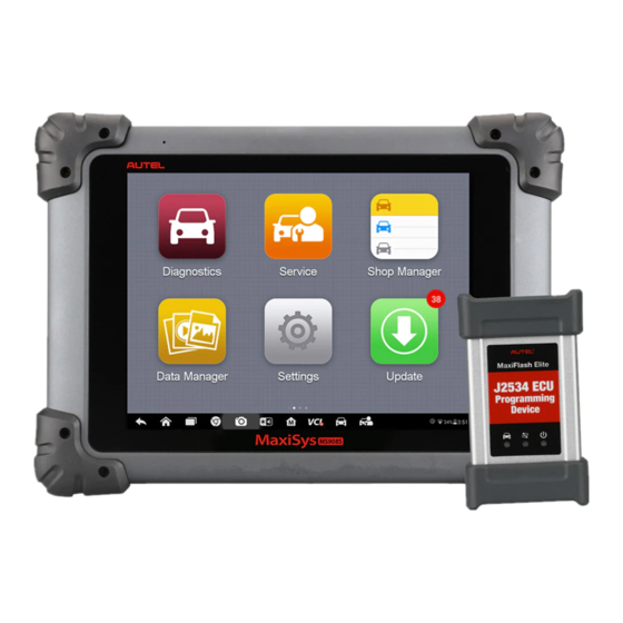
Page 9: Tablet
Vehicle Communication Interface (VCI) – the device for accessing vehicle data. NOTE Autel provides two optional VCI devices for your choice. One is the Wireless Diagnostic Interface; the other is the J2534 Programming Device, both will be introduced in this chapter. - Page 10 Labelling Place 9.7” LED Capacitive Touch Screen Ambient Light Sensor – detects ambient brightness. Microphone Figure 2-2 MaxiSys Tablet Back View Audio Speaker Collapsible Stand – extends from the back to allow hands-free viewing of the tablet at a 30 degree angle. Camera Lens Camera Flash Figure 2-3 MaxiSys Tablet Left Side...
- Page 11 Figure 2-4 MaxiSys Tablet Top View DC Power Supply Input Port HDMI (High-Definition Multimedia Interface) Port USB Port USB Port (it cannot be used at the same time with the Mini USB Port in Figure 2-3 MaxiSys Tablet Left Side) Lock/Power Button –...
- Page 12 0 to 50° C (32 to 122° F) Storage Temp. -20 to 60° C (-4 to 140° F) Dimensions ( 300 mm (11.81”) x 220 mm (8.66”) x 50 mm (1.97”) WxHxD NW: 1.42 kg (3.13 lb.) Weight MaxiSys MS908S GW: 8.655 kg (19.08 lb.)
- Page 13 TP 1.6, SAE J1939, SAE J1708, Fault-Tolerant CAN VCI – Wireless Diagnostic Interface Functional Description Figure 2-5 Wireless Diagnostic Interface – for MaxiSys MS908S Vehicle Data Connector (DB15-Pin) Power LED – lights solid green when the device is powered on.
-
Page 14: Device
The unit powers on whenever it is connected to an OBD II/EOBD compliant data link connector (DLC). VCI – J2534 ECU Programming Device Functional Description Figure 2-6 J2534 ECU Programming Device – for MaxiSys MS908S Pro... - Page 15 DC Power Supply Input Port Vehicle Data Connector Vehicle LED Flashes green when the device is communicating with the vehicle’s system IMPORTANT Do not disconnect the programming device while this status light is on! If the flash programming procedure is interrupted while the vehicle’s ECU is blank or only partially programmed, the module may be unrecoverable.
- Page 16 Vehicle Power The J2534 programming device operates on 12-volt vehicle power, which it receives through the vehicle data connection port. The device powers on whenever it is connected to an OBD II/EOBD compliant data link connector (DLC). For non OBD II/EOBD compliant vehicles, the device can be powered from a cigarette lighter or other suitable power port on the test vehicle using the auxiliary power cable.
- Page 17 The OBD I adapters are for Non-OBD II vehicles. The adapter used depends on the type of vehicle being tested. The most common adapters are shown below (Adapters PSA-2 and Fiat-3 are available for MaxiSys MS908S Pro only). Benz-14 Chrysler-16...
- Page 18 II vehicles cannot provide power via the DLC connection. Clipper Cable Provides power to the tablet the J2534 programming device through connection to the vehicle’s battery (for MaxiSys MS908S Pro only). Lighter Fuse x2 A safety device for the cigarette lighter.
-
Page 19: Power Up
Getting Started Make sure the tablet has sufficient power or is connected to the external power supply (see Power Sources on page 5). Power Up Long press the Lock/Power button on the top right side of the tablet to switch the unit on. The power LED will illuminate green. - Page 20 Accesses VCI connection menu. See VCI Manager Manager on page 82. Launches the Support platform that synchronizes Support Autel’s on-line service base station with the MaxiSys tablet. See Support on page 86. Accesses technical tutorials and training articles Academy about the device or vehicle diagnostic techniques.
- Page 21 Name Button Description Configures the unit to operate as an automotive oscilloscope to perform electrical and electronic MaxiScope circuit tests and monitor signal activities. See MaxiScope on page 96. Configures the unit to operate as a video scope Digital device by connecting to an Imager head cable for Inspection close vehicle inspections.
- Page 22 Name Button Description Opens the VCI Manager application. The check at the bottom right corner indicates the tablet is communicating with the VCI, an X will display if the tablet is not connected to VCI. MaxiSys Returns to the Diagnostics screen. Shortcut Service Returns to the Service screen.
- Page 23 Reboot System In case of system crash, long press the Lock/Power button and tap Reboot to restart the system.
- Page 24 When these are done, check the VCI navigation button at the bottom bar on the screen, if a green check displays at the lower right corner, the MaxiSys MS908S/MaxiSys MS908S Pro Diagnostic Platform is ready to start vehicle diagnosis. Vehicle Connection The method used to connect the VCI device to a vehicle’s DLC depends on the...
- Page 25 Connect the male connector of the cigarette lighter into the vehicle’s cigarette lighter receptacle. To connect the clipper cable - for MaxiSys MS908S Pro only Connect the tubular plug of the clipper cable to the male connector of the cigarette lighter.
- Page 26 The Wireless Diagnostic Interface, which comes with the MaxiSys MS908S tool kit, supports 2 communication methods with the tablet: BT and USB. The J2534 ECU Programming Device, which comes with the MaxiSys MS908S Pro tool kit, supports 2 communication methods with the tablet: BT, and USB.
- Page 27 Select the VCI Manager application from the MaxiSys Job Menu. When the VCI Manager application is opened, the device automatically starts scanning for available VCI devices around for BT pairing. The found devices are listed in the Setting section on the right side of the screen. NOTE If no VCI device is found, this may indicate that the signal strength of the transmitter is too weak to be detected.
-
Page 28: Getting Started
In case of wireless connection, check if the network is configured correctly, or if the right device has been paired. If during the diagnosis process, the communication is suddenly interrupted due to the loss of signal, check if there is any object that causes signal interruption. - Page 29 Figure 4-2 Sample Vehicle Menu Screen Top Toolbar Buttons Manufacturer Buttons Top toolbar Buttons The operations of the Toolbar buttons at the top of the screen are listed and described in the table below: Table 4-1 Top Toolbar Buttons Name Button Description Home...
- Page 30 Name Button Description Asia Displays the Asian vehicle menu. Domestic Displays the Domestic vehicle menu. Touching this button opens the virtual keyboard, Search allowing you to manually enter the specific vehicle make required. Touching this button exits the search screen, or Cancel cancels an operation.
- Page 31 Vehicle Diagnostics screen directly. Figure 4-3 Sample Vehicle Diagnostics Screen In some cases when users have selected the vehicle brand instead of performing Auto VIN Scan in the first place, the system still provides an option for vehicle VIN scan. Figure 4-4 Sample Vehicle Selection Screen Select Automatic Selection and the system will proceed to acquire VIN information automatically or allow users to input the VIN manually.
- Page 32 To perform Manual VIN Input Tap the Diagnostics application button from the MaxiSys Job Menu. The Vehicle Menu displays. Tap the VIN Scan button on the top toolbar. Select Manual Input. Tap the input box and enter the correct VIN. Figure 4-5 Manual VIN Input Tap Done.
- Page 33 Navigation This section describes how to navigate the Diagnostics interface and select test options. Diagnostics Screen Layout The Diagnostics screens typically include four sections. Figure 4-6 Sample Diagnostics Screen Diagnostics Toolbar Status Information Bar Main Section Functional Buttons Diagnostics Toolbar The Diagnostics Toolbar contains a number of buttons that allow you to print or save the displayed data and make other controls.
- Page 34 Name Button Description Saves and prints a copy of the displayed data. See Print Print on page 7676. Provides instructions or tips for operations of Help various diagnostic functions. Taps it to open a submenu, on which there are 3 options available to save the displayed data.
- Page 35 To submit Data Logging reports in Diagnostics Tap the Diagnostics application button from the MaxiSys Job Menu. The Data Logging button on the diagnostic toolbar is available throughout the whole Diagnostics operations. Tap the Data Logging button. The button displays blue during the active recording process.
-
Page 36: Main Menu
When a user-response is not required to continue, the message displays briefly before automatically disappearing. Warning Messages This type of messages informs you when completing the selected action may result in an irreversible change or loss of data. The typical example for this is the “Erase Codes” message. -
Page 37: D Iagnosis
Diagnosis There are two options available when accessing the Diagnosis section: Auto Scan – starts auto scanning for all the available systems on the vehicle Control Units – displays a selection menu of all available control units of the test vehicle. - Page 38 Column 3 – displays the diagnostic marks indicating different conditions of the test result. -!-: Indicates that the scanned system may not support the code reading function, or there is a communication error between the tester and the control system. -?-: Indicates that the vehicle control system has been detected, but the tester cannot accurately locate it.
- Page 39 Name Description Saves the diagnostic session as a history record, this allows Save you to quickly restore access to the test systems. Control Units This option allows you to manually locate a required control system for testing through a series of choices. Simply follow the menu driven procedure, and make proper selection each time;...
- Page 40 selection may sometimes appear as Control Unit Adaptations, Variant Coding, Configuration or something similar. NOTE With the diagnostic toolbar on top of the screen throughout the whole diagnostic procedures, you are allowed to make various controls of the diagnostic information at any time, such as printing and saving the displayed data, get help information, or perform data logging, etc.
- Page 41 available; tap it to exit after viewing. Read Codes This function retrieves and displays the DTCs from the vehicle’s control system. The Read Codes screen varies for each vehicle being tested, on some vehicles, freeze frame data can also be retrieved for viewing. The sample Read Codes screen displays as below: Figure 4-10 Sample Read Codes Screen Diagnostics Toolbar Buttons –...
- Page 42 To erase codes Tap Erase Codes from the Function Menu. A warning message displays to inform you of data loss when this function is applied. Tap Yes to continue. A confirming screen displays when the operation is successfully done. Tap No to exit.
- Page 43 Check Box – tap the check box at the left side of the parameter name to make selection of an item. Tap the check box again to deselect the item. Drop-down Button – tapping the drop-down button at the right side of the parameter name opens a submenu, which provides various choices for data display mode.
- Page 44 waveform color and the line thickness displayed for the selected parameter item. Scale Button – changes the scale values, which are displayed below the waveform graph. There are four scales available: x1, x2, x4 and x8. Zoom-out Button – exits full screen display. ...
- Page 45 parameters. NOTE This mode supports Graph Merge for 2 to 3 parameter items only, so select no less than 2 or more than 3 items each time when making graph merge. To cancel Graph Merge mode, tap the drop-down button on the right side of the parameter name, and select a data display mode.
- Page 46 Tap the Setting button at the bottom of the Live Data screen. Tap the Range navigation button. Select a parameter item on the left column, or enter the item name in the Search bar. Tap on the right side of the MIN button, and enter the required minimum value.
- Page 47 Tap the button on the right of Trigger Point bar and select a relative percentage of a record length to be reserved before the data recording start point. Tap Done to save the setting and return to the Live Data screen; or tap Cancel to cancel without saving and exit Setting.
- Page 48 The functional buttons at the lower right corner of the Active Test screen manipulate the test signals. The operational instructions are displayed on the main section of the test screen. Simply follow the on-screen instructions and make appropriate selections to complete the tests.
-
Page 49: Coding
Read the information carefully and check the vehicle condition accordingly, when you are sure that the vehicle is ready to perform the adaptation, simply follow the instruction provided to make appropriate selections. When the operation is done, an execution status message such as Completed, Finished or Successful, displays. Tap the ESC button to exit the function. - Page 50 NOTE Ensure that the tablet is connected to the Internet before applying the ECU programming function, so that the tablet is able to obtain access to the manufacturer’s server for update service. Selecting the Programming or Coding function opens a menu of operation options that varies by make and model.
- Page 51 Reprogramming Operation Typical reprogramming operations require you to input and validate VIN number first. Tap the input box and enter the correct number, the programming interface then displays. Figure 4-16 Sample Reprogramming Operation Screen The main section of the reprogramming interface provides you certain hardware version, and current software versions’...
-
Page 52: Perations
If the process crashes, recheck all the cable connections to assure good communications and reinitialize the flash procedure. The programming procedure will automatically repeat if the previous operation does not succeed. Generic OBD II Operations A fast-access option for OBD II/EOBD vehicle diagnosis is available on the Vehicle Menu screen. - Page 53 Figure 4-17 Sample OBD II Diagnostic Menu NOTE button displayed beside the function name is tappable, tapping which opens a bubble with additional function information. Select a function option to continue. DTC & FFD I/M Readiness Live Data ...
- Page 54 function can be applied by tapping the functional button at the lower bottom of the screen. Figure 4-18 Sample DTC & FFD Screen Stored Codes Stored codes are the current emission related DTCs from the ECM of the vehicle. OBD II/EOBD Codes have a priority according to their emission severity, with higher priority codes overwriting lower priority codes.
- Page 55 the time the DTC is set. Erase Codes This option is used to clear all emission related diagnostic data such as, DTCs, freeze frame data and manufacturer specific enhanced data from the vehicle’s ECM, and resets the I/M Readiness Monitor Status for all vehicle monitors to Not Ready or Not Complete status.
- Page 56 Component Test This service enables bi-directional control of the ECM so that the diagnostic tool is able to transmit control commands to operate the vehicle systems. This function is useful in determining how well the ECM responds to a command. Vehicle Information The option displays the vehicle identification number (VIN), the calibration identification, and the calibration verification number (CVN), and other information of the test vehicle.
- Page 57 Service The Service section is specially designed to provide quick access to the vehicle systems for various scheduled service and maintenance tasks. The typical service operation screen is a series of menu driven executive commands. Follow on-screen instructions to select appropriate execution options, enter correct values or data, and perform necessary actions.
-
Page 58: Ervice
Ensure that the EPB control system is reactivated after the maintenance work has been completed. NOTE Autel accepts no responsibility for any accident or injury arising from the maintenance of the Electric Parking Brake system. Tire Pressure Monitoring System (TPMS) Service This function allows you to quickly look up the tire sensor IDs from the vehicle’s ECU,... -
Page 59: Bms) S Ervice
Battery Management System (BMS) Service The Battery Management System (BMS) allows the tool to evaluate the battery charge state, monitor the close-circuit current, register the battery replacement, activate the rest state of the vehicle, and charge the battery via the diagnostic socket. NOTE This function is not supported by all vehicles. - Page 60 NOTE Autel accepts no responsibility for any accident or injury arising from servicing the SAS system. When interpreting DTCs retrieved from the vehicle, always follow the manufacturer’s recommendation for repair. All software screens shown in this manual are examples, actual test screens may vary by test vehicle.
- Page 61 other person observes the screen on the Tool. Do not attempt to drive and observe the scan tool at the same time. This is dangerous and puts your life and the lives of other motors and pedestrians at risk. Immobilizer (IMMO) Service An immobilizer is an anti-theft mechanism that prevents an automobile’s engine from starting unless the correct ignition key or other device is present.
-
Page 62: N Avigation
MaxiFix The MaxiFix application launches the on-line troubleshooter database, which not only provides you virtually all common diagnostic trouble code (DTC) database for most vehicles, but also serves as a forum allowing you to network with other MaxiSys users, and gives you access to a vast database of repair and diagnostic tips along with proven filed fixes. - Page 63 The Main Screen – located at the center of the screen displaying content based on the vehicle attributes and keywords specified. The tabs on the main screen vary in accordance with the section selected on the Navigation Menu, allowing you to switch between functions.
- Page 64 Terminology MaxiFix Tip A MaxiFix Tip provides practical information of real fix of a specific vehicle repair issue with detailed descriptions. It is combined with proven fix and vehicle specific data, and filed into an all-in-one information source to provide you with quick and easy repair solutions.
- Page 65 Adopted! The “Adopted!” icon that displays at the top right side of a Tip page indicates that the related Tip has been adopted by at least 1 technician in the community. If a tip has helped you to solve a repair problem, you are encouraged to give an Adopted! count to the tip.
- Page 66 Search Fix Features Search Fix, the second option on the Navigation Menu at the bottom of the screen, presents search results for the specified vehicle. Search results are listed in various categories: All – includes all search results, including related Questions, Tips, and Real Fixes ...
- Page 67 Marked Posts – opens a list with links to Tips and discussions that you are actively participating in. My Profile – allows you to view your Autel account information including: your Autel ID, personal information, MaxiFix score, phone number and register time, and edit your portrait.
- Page 68 Use the Cancel button at the right-side bottom of the page to cancel your tip and return to the My MaxiFix page. Or, Use the Submit button at the right-side bottom of the page to contribute your tip to the community. Use the Attach File button at the left-side bottom of the page to include images or other supporting data with your question.
- Page 69 Answers can only be rated by the MaxiFix member who asked the question. Close a Question When a repair question that you've posted to the community is resolved, you are encouraged to write down the case as a way to share a good solution. This will help the other MaxiFix members to find useful information for practical fix.
- Page 70 Shop Manager The Shop Manager application helps you to manage the workshop information, customer information records, and keep test vehicle history records, which can be a great assist in dealing with daily workshop business and improves customer service. There are three main functions available: ...
- Page 71 Vehicle History This function stores records of test vehicle history, including vehicle information and the retrieved DTCs from previous diagnostic sessions, and displays all information in an easy-to-check table list, on which you can view summarized details and manually input other information about the test vehicle and diagnostic loggings, etc.
- Page 72 Historical Test Record The Historical Test record sheet of the tested vehicle is a detailed data form, which includes all general information of the vehicle such as vehicle year, make and model, etc., and the diagnostic trouble codes retrieved from the previous test sessions, as well as other service details which can be added manually by the technician himself.
- Page 73 Workshop Information The Workshop Information form allows you to edit, input and save the detailed workshop information, such as shop name, address, phone number and other remarks, which, when printing vehicle diagnostic reports and other associated test file, will appear as the header of the printed documents. Figure 7-3 Sample Workshop Information Sheet ...
- Page 74 NOTE The items that must be filled are indicated as required fields. Tap the photo frame beside the Name chart to add a photo. A sub menu displays, select Take Photo to take a new photo for the account, or select Choose Photo to choose from the existing files.
- Page 75 Select Customer Manager or Vehicle History. Select a customer account by tapping the corresponding name card. A Customer Information sheet displays (if Customer Manager is selected). Or, select a vehicle history record item to open the Historical Test record sheet (if Vehicle History is selected).
- Page 76 Name Button Description Audio Performs audio recording and creates audio Record files. Opens the image file for selection, and adds Add Photos the selected photos to History Notes. Records a video and adds the file to History Take a Video Notes.
- Page 77 Data Manager The Data Manager application is used to store, print, and review the saved files. Most operations are controlled through the toolbar. Selecting the Data Manager application opens the file system menu. Different file types are sorted separately under different options, there are six types of information files to be viewed or played back.
- Page 78 Figure 8-2 Sample Image Database Screen Toolbar Buttons – used to edit, print and delete the image files. See Table 8-1 Toolbar Buttons in JPG Database on page 72 for detailed information. Main Section – displays the stored images. Table 8-1 Toolbar Buttons in JPG Database Name Button Description...
- Page 79 Tap Edit on the top right corner of the window. The editing screen displays. Edit the image information by entering the new file name, and file information. Tap Done to save the information and exit, or tap Cancel to exit without saving.
- Page 80 Drop-down Toolbar – taps the button at the top center of the screen to open the Drop-down Toolbar. Main Section – displays the recorded data frames. Navigation Toolbar – allows you to manipulate data playback. Use the Navigation Toolbar buttons to playback the record data from frame to frame. Tap Back to exit data playback.
- Page 81 Settings Selecting Settings application opens a setup interface, on which you can adjust default setting and view information about the MaxiSys system. There are eight options available for the MaxiSys system settings: Unit Language Printing Setting Wired Network ...
- Page 82 Printing Operations To install the MaxiSys Printer driver program Download Maxi PC Suite from www.autel.com > Supports & Updates > Firmware & Downloads > Update Client, and install to a Windows-based PC. Double click on Setup.exe item. Select the installation language and the wizard will load momentarily.
- Page 83 Run the MaxiSys Printer program on the computer. Click Test Print to make sure the printer is working successfully. Tap the Print button on the toolbar. A test document will automatically be sent to the computer for printing when Auto Print option is selected. Tap the Print button on the toolbar of the tablet.
- Page 84 Internet. It is highly recommended to keep this function on all the time, so you won’t miss out any new update for MaxiSys or event from Autel. Internet access is required for receiving on-line messages.
- Page 85 Auto Update This option allows you to set the specific time for updating software automatically. There are three update options: OS Update, MaxiSys Update and Vehicle Update. Tap ON/OFF to enable Auto Update. If the connectivity is enabled the button turns blue, or if disabled the button turns gray.
- Page 86 Update The internal programming of the MaxiSys Diagnostic System, known as the firmware, can be updated using the Update application. Firmware updates increase the MaxiSys applications’ capabilities, typically by adding new tests, new models, or enhanced applications to the database. The display device automatically searches for available updates for all of the Maxisys components when it is connected to the internet.
- Page 87 tap the About button displays a function list in PDF showing more details about the firmware. Middle Column – displays a brief introduction about the new changes to the firmware operation or capabilities. Tap button to open an information screen to view more details, and tap the dim area around to close the window.
- Page 88 VCI Manager This application allows you to pair up the tablet with the VCI device, either the J2534 Programming Device or the Wireless Diagnostic Interface, and to check the communication status. Figure 11-1 Sample VCI Manager Screen Connection Mode – there are two connection modes available for selection. The connection state is displayed alongside.
- Page 89 Power on the tablet. Connect the 26-pin end of the data cable to the J2534 ECU Programming Device’s vehicle data connector (for MaxiSys MS908S Pro); Or connect the 15-pin end of the data cable to the Wireless BT Diagnostic Interface’s vehicle data connector (for MaxiSys MS908S).
- Page 90 You can use the application to receive ad-hoc remote support from Autel’s support centre, colleagues, or friends, by allowing them to control your MaxiSys tablet on their PC via the TeamViewer software.
- Page 91 (http://www.teamviewer.com), and then start the software on his/her computer at the same time, in order to provide support and take control of the tablet remotely. Provide your ID to the partner, and wait for him/her to send you a remote control request.
- Page 92 If you already have and Autel account, Sing In with your account ID and password. If you are a new member to Autel, click on the Create Autel ID button on the left side to create an ID. Enter the required information in the input fields, and click Get Verification Code button to get the verification code for email validation.
- Page 93 Personal Info The User Info and Device Info are both included under the Personal Info section. User Info – displays detailed information of your registered on-line Autel account, such as your Autel ID, Name, Address and other contact information, etc.
- Page 94 The Service Info section displays a detailed record list of the device’s service history information. Every time the device has been sent back to Autel for repair, the device’s serial number and the detailed repair information, such as the fault type, changed...
- Page 95 Select the required processing time on the last section according to the urgency of the case. Tap Submit to send the completed form to Autel’s online service center, or tap Reset to refill it. The submitted complaints will be carefully read and handled by the service personnel, and the respond speed may depend on the processing time you’ve required.
- Page 96 Select an existing complaint case item on the record list by tapping the button on its right side. The screen displays the complaint session details. Tap the Post Reply button on the upper right side after viewing, to make a reply.
- Page 97 Communities The Communities section launches and synchronizes with the Technical Forums on Autel’s official website www.autel.com, where you are allowed to discuss technical topics or share information with, as well as ask for technical advices or offer technical supports to all other members in Autel’s online support communities.
- Page 98 Training Channels The Training section provides quick links to Autel’s online video accounts. Select a video channel by the language to see all the available online tutorial videos from Autel for various technical supports, such as product usage techniques and vehicle...
- Page 99 The FAQ section provides you comprehensive and abundant references for all kinds of questions frequently asked and answered about the use of Autel’s online member account, and shopping and payment procedures. Account – displays questions and answers about the use of Autel’s online user account.
- Page 100 Academy Autel provides various tutorial articles and technical bulletins produced by top-notch technicians and product experts. Please view the materials that are saved on the tablet or view technical articled from our online forum by clicking the links displayed under this...
- Page 101 Quick Link The Quick Link application provides you with convenient access to Autel’s official website and many other well-known sites in automotive service, which offers you abundant information and resources, such as technical help, knowledge base, forums, training, and expertise consultations, etc.
- Page 102 MaxiScope The MaxiScope application configures the MaxiSys Diagnostic Device to operate as an automotive oscilloscope when work in combination with the MaxiScope module. This function provides all the features needed for performing electrical and electronic circuit tests as well as monitoring signal activities on any modern vehicles, which shows you what is really going on with a vehicle’s electrical system.
- Page 103 96. E. Product Maintenance The product contains no user-serviceable parts. Repair, servicing and calibration require specialized test equipment and must only be performed by Autel Tech Support or an approved service provider. DANGER To prevent injury or death, do not use the product if it appears to be damaged in any way, and stop use immediately if you are concerned by any abnormal operations.
-
Page 104: Sampling Rate
Glossary AC/DC Control Each channel can be set to either AC coupling or DC coupling. With DC coupling, the voltage displayed onscreen is equal to the true voltage of the signal with respect to ground. With AC coupling, any DC component of the signal is filtered out, leaving only the variations in the signal for the AC component. - Page 105 Streaming Mode This term indicates a sampling mode in which the oscilloscope samples data and returns it to the computer in an unbroken stream. This mode of operation is effective when the input signal being sampled is at low frequency. Time Base The time base controls the time interval across the scope display.
- Page 106 Square Waveform This term describes the waveform characteristics normally generated by signals switching between clearly defined voltage levels, such as a Hal effect sensor signal may create by switching a voltage to ground. A typical digital square waveform is shown below. Figure 16-2 Sample Square Waveform Peak to peak voltage This term indicates the difference in voltage between the minimum and maximum...
- Page 107 Figure 16-3 Front, Rear, and Top View USB Port Connector Input Channel A/B/C/D LED Indicator Light – lights up when powered on, blinks when communicating, and shimmers when error occurs Warning Triangle – indicates potential safety hazard that exists on the indicated connections, and appropriate precautions should be taken.
- Page 108 Bandwidth 20MHz Accuracy Voltage: 1%; Time: 50ppm Sensitivity 10mV/div to 20V/div Input Ranges (full scale) ±50mV to ±100V in 11 ranges 1MΩ in parallel with 22pF Input Impedance Input Type Single-ended, BNC connector Input Coupling Software selectable AC/DC Overload Protection ±200V on single input Max.
- Page 109 Compliance FCC (EMC), CE (EMC and LVD), RoHS Warranty 1 year NOTE Reduced to 20MS/s if channels A and B, or C and D, are enabled. Screen Layout and Operations The MaxiScope application works as a signal processing program that displays the shape of electrical signals onscreen with a live graph showing voltage against time.
- Page 110 Top Toolbar The top toolbar contains various functional buttons with options for operations and configurations of the MaxiScope, the operations of which are described in the table below: Table 16-2 Toolbar Buttons Name Button Description This option provides a library of waveforms. Selecting one allows automatic set-up of the scope to capture a waveform of the specified waveform type.
- Page 111 Name Button Description Provides instructions or tips for operations of Help various functions. Indicates the scope connection status. Tapping Scope the icon allows to reset the USB connection when Icon communication with the Scope Module fails. See Troubleshooting on page 109. Math Channel A math channel is virtual channel generated by mathematical function of the input channel.
- Page 112 Select the channel to which the desired waveform belongs. Name the reference waveform by selecting R1, R2, R3 or R4 in the popup window. Tap on the Yes to save, or No icon to cancel. Recall Reference The saved reference waveforms can be retrieved by clicking Recall Ref in the dropdown menu of the Tool button.
- Page 113 AutoScale – taps it to enable automatic set-up of the voltage scale and time base for the signals received. Start/Stop – taps it to turn on/off the scope. Single – taps it to activate the Single trigger mode when the trigger is on. The ...
- Page 114 gestures. The 0 volts is hinted with a pointer reference line. Slide the pointer up and down to move and view different areas of the scale. Tap once on the screen area outside of the Y-axis to finish the voltage scale adjustment.
-
Page 115: Troubleshooting
Functional Buttons This group of buttons includes trigger setting buttons allowing you to set trigger source and trigger mode, a Time base button for adjustment, and a Measurement button with options for various measurement types. Trigger On/Off – taps to turn on/off the trigger. The button displays as Trigger Off ... - Page 116 MaxiScope Firmware Update The operating software of the MaxiScope is continuously being developed, and the update package can be downloaded free from the MaxiScope product webpage on Autel’s website: http://www.autel.com. To update the MaxiScope firmware Install the CD provided with the MaxiScope tool kit into the CD-ROM of the computer.
- Page 117 Digital Inspection The Digital Inspection application configures the MaxiSys Diagnostic Device to operate as a digital video scope by simply connecting the tablet to a Digital Inspection Camera. This function allows you to examine difficult-to-reach areas normally hidden from sight, with the ability to record digital still images and videos, which offers you an economical solution to inspect machinery, facilities, and infrastructure in a safe and quick way.
- Page 118 Additional Accessories The Digital Inspection Camera and its fittings are the additional accessories. Both sizes (8.5 mm and 5.5 mm) of the imager head are optional and available for purchase along with the standard MaxiSys tool kit. Digital Inspection Camera Figure 17-1 Digital Inspection Camera Removable Imager Head Cable –...
- Page 119 Magnet – picks up small metal objects, such as dropped rings or screws. Hook – unclogs obstacles and picks up wires in the pipes or confined areas. Mirror – helps to look around corners and see the unreachable areas. Figure 17-3 5.5mm Imager Head Accessories Mirror –...
- Page 120 Hold the accessory and the imager head. Screw the thread part of the accessory over the imager head to fix the accessory. Technical Specifications Table 17-1 Specifications Item Description Optimal Viewing 1" to 14" (2.54cm to 35.56cm) with 8.5mm Distance diameter imager head 3/8"...
- Page 121 Cable: -10° C to 70° C Storage Temperature -20° C to 75° C (ambient) Waterproof Imager head and cable to 1m Weigh 0.3 kg with 8.5 mm diameter imager head 0.2 kg with 5.5 mm diameter imager head Operations Before performing the Digital Inspection application, the Imager Head Cable must be connected to the tablet through the USB port.
- Page 122 Select the video icon at the lower right corner to record a video. Properly locate the imager head cable to focus the inspection scene for recording. Tap the red ring on the operating screen to start recording. Tap the red circle again to stop recording. The recorded video is automatically saved to the system Gallery.
-
Page 123: Maintenance And Service
Maintenance and Service To ensure that the tablet and the combined VCI unit perform at their optimum level, we advise that the product maintenance instructions covered in this section is read and followed. Maintenance Instructions The following shows how to maintain your devices, together with precautions to take. ... - Page 124 Your device may have not been connected to the charger properly. Check the connector. NOTE If your problems persist, please contact Autel’s technical support personnel or your local selling agent. About Battery Usage Your tablet is powered by a built-in Lithium-ion Polymer battery. This means that, unlike other forms of battery technology, you can recharge your battery while some charge remains without reducing your tablet’s autonomy due to the “battery memory effect”...
-
Page 125: Service Procedures
This section introduces information for technical support, repair service, and application for replacement or optional parts. Technical Support If you have any question or problem on the operation of the product, please contact us. AUTEL NORTH AMERICA Phone: 855-AUTEL-US (855-288-3587) Monday-Friday 9am-6pm EST Website: www.autel.com Email: ussupport@autel.com... - Page 126 For technical assistance in other markets, please contact your local selling agent. Repair Service If it becomes necessary to return your device for repair, please download the repair service form from www.autel.com, and fill in the form. The following information must be included: ...
- Page 127 Other Services You can purchase the optional accessories directly from Autel’s authorized tool suppliers, and/or your local distributor or agent. Your purchase order should include the following information: Contact information Product or part name Item description ...
- Page 128 Compliance Information FCC Compliance FCC ID: WQ8MAXISYSMS908S This equipment has been tested and found to comply with the limits for a Class B digital device, pursuant to Part 15 of the FCC Rules. These limits are designed to provide reasonable protection against harmful interference in a residential installation. This equipment generates uses and can radiate radio frequency energy and, if not installed and used in accordance with the instructions, may cause harmful interference to radio communications.
- Page 129 power required to reach the network. To avoid the possibility of exceeding the FCC radio frequency exposure limits, human proximity to antenna should be minimized.
- Page 130 Warranty 12-Month Limited Warranty Autel Intelligent Technology Corp., Ltd. (the Company) warrants to the original retail purchaser of this MaxiSys Diagnostic Device that should this product or any part thereof during normal usage and under normal conditions be proven defective in...
Need help?
Do you have a question about the MaxiSys MS908S and is the answer not in the manual?
Questions and answers