Table of Contents
Advertisement
Advertisement
Chapters
Table of Contents

Related Manuals for Zte ZXR10 1800-2S


Summary of Contents for Zte ZXR10 1800-2S
- Page 1 ZXR10 ZSR V2 Intelligent Integrated Multi-Service Router Hardware Description Version: 2.00.20 ZTE CORPORATION No. 55, Hi-tech Road South, ShenZhen, P.R.China Postcode: 518057 Tel: +86-755-26771900 Fax: +86-755-26770801 URL: http://support.zte.com.cn E-mail: support@zte.com.cn...
- Page 2 ZTE CORPORATION is prohibited. Additionally, the contents of this document are protected by contractual confidentiality obligations. All company, brand and product names are trade or service marks, or registered trade or service marks, of ZTE CORPORATION or of their respective owners.
-
Page 3: Table Of Contents
3.2 Power Supply..................... 3-3 3.2.1 AC Power Supply Module ................. 3-4 3.2.2 DC Power Supply Module ................. 3-5 3.3 Fan ........................3-6 Chapter 4 ZXR10 1800-2S Chassis ............4-1 4.1 Structure......................4-1 4.1.1 Overview and Structure ................4-1 4.1.2 Slot Layout ....................4-4 4.1.3 System Parameters .................. - Page 4 9.11 RAC-PIU-04CE1-75..................9-18 9.12 RAC-PIU-04CE1-120..................9-19 9.13 RAC-PIU-04UE1-75 ..................9-21 9.14 RAC-PIU-04UE1-120..................9-22 9.15 RAC-PIU-16CE1 .................... 9-23 9.16 RAC-PIU-16CE1-CES ..................9-25 9.17 RAC-PIU-01P12-SFP ..................9-26 9.18 RAC-PIU-02P3-SFP ..................9-28 9.19 RAC-PIU-04P3-SFP ..................9-29 9.20 RAC-PIU-02CP3-SFP..................9-31 SJ-20150204153047-004|2015-03-30 (R1.0) ZTE Proprietary and Confidential...
- Page 5 10.2.5 SHDSL Cables ..................10-9 10.2.6 Synchronous/Asynchronous Serial Cable..........10-10 10.2.7 E1 Trunk Cable ...................10-13 Appendix A Board Quick Table (Weight and Power Consumption)..A-1 Appendix B Optical Modules Quick Table..........B-1 Figures......................I Tables ......................V Glossary ......................XIII SJ-20150204153047-004|2015-03-30 (R1.0) ZTE Proprietary and Confidential...
- Page 6 This page intentionally left blank. SJ-20150204153047-004|2015-03-30 (R1.0) ZTE Proprietary and Confidential...
-
Page 7: About This Manual
Describes the structure, components, slot layout, system Chapter 4, ZXR10 1800-2S Chassis parameters, power supplies, and the heat dissipation sys- tem of the ZXR10 1800-2S chassis. Describes the structure, slot deployment, system pa- Chapter 5, ZXR10 2800-3E Chassis rameters, power modules, and fan modules of a ZXR10 2800-3E chassis. - Page 8 Caution: indicates a potentially hazardous situation. Failure to comply can result in moderate injury, equipment damage, or interruption of minor services. Note: provides additional information about a certain topic. SJ-20150204153047-004|2015-03-30 (R1.0) ZTE Proprietary and Confidential...
-
Page 9: Chapter 1 Hardware Overview
Component Model Description Cabinet Used as required. The ZXR10 1800-2S is a desktop product, the ZXR10 1800-2E and ZXR10 2800-3E can be installed on a desktop or in a cabinet, while the ZXR10 2800-4 and ZXR10 3800-8 can be installed in an IEC297 standard cabinet or ETSI standard cabinet. - Page 10 ZXR10 ZSR V2 Hardware Description This page intentionally left blank. SJ-20150204153047-004|2015-03-30 (R1.0) ZTE Proprietary and Confidential...
-
Page 11: Structure
× 200 mm). For the main components of the ZXR10 3800-8 chassis, see Figure 2-1. Figure 2-1 Main Components on the Front Side of the ZXR10 3800-8 Chassis For the front view of the ZXR10 3800-8 chassis, see Figure 2-2. SJ-20150204153047-004|2015-03-30 (R1.0) ZTE Proprietary and Confidential... -
Page 12: Slot Layout
For a front view of the ZXR10 3800-8 chassis, see Figure 2-3. Figure 2-3 Front View of the ZXR10 3800-8 Chassis The ZXR10 3800-8 chassis provides nine service slots and boards are horizontally installed in the chassis. SJ-20150204153047-004|2015-03-30 (R1.0) ZTE Proprietary and Confidential... -
Page 13: System Parameters
100 V AC to 240 V AC Input frequency range 50 Hz to 60 Hz Rated output power per 250 W module Heat dissipation system Number of fan modules Grounding resistance Resistance of joint grounding < 5 Ω SJ-20150204153047-004|2015-03-30 (R1.0) ZTE Proprietary and Confidential... -
Page 14: Power Supply
Table 2-3 Indicator Descriptions for the ZXR10 3800-8 AC Power Supply Module Indicator Number Color Description Green Indicates that the power supply module operates properly. Indicates that the power supply module has an alarm. SJ-20150204153047-004|2015-03-30 (R1.0) ZTE Proprietary and Confidential... -
Page 15: Dc Power Supply Module
For the front view of the DC power supply module of the ZXR10 3800-8, see Figure 2-5. Figure 2-5 Panel of the DC Power Supply Module Indicators For a description of the ZXR10 3800-8 DC power supply indicators, refer to Table 2-6. SJ-20150204153047-004|2015-03-30 (R1.0) ZTE Proprietary and Confidential... -
Page 16: Fan Module
The fan module can automatically adjust the fan speed according to the equipment operation and supports the status monitoring and alarm functions. For the technical specifications of the ZXR10 3800-8 fan module, refer to Table 2-9. SJ-20150204153047-004|2015-03-30 (R1.0) ZTE Proprietary and Confidential... -
Page 17: Table 2-9 Zxr10 3800-8 Fan Specifications
Size (W × H × D) 40.8 mm ×125.7 mm ×186 mm Weight 0.62 kg Power consumption 45 W Maximum wind pressure 23 mmH Maximum wind 287 CFM Maximum noise 60 dBA Operation voltage 12 V SJ-20150204153047-004|2015-03-30 (R1.0) ZTE Proprietary and Confidential... - Page 18 ZXR10 ZSR V2 Hardware Description This page intentionally left blank. SJ-20150204153047-004|2015-03-30 (R1.0) ZTE Proprietary and Confidential...
-
Page 19: Structure
× 200 mm). For the main components of the ZXR10 2800-4 chassis, see Figure 3-1. Figure 3-1 Main Components on the Front Side of the ZXR10 2800-4 Chassis For the front view of the ZXR10 2800-4 chassis, see Figure 3-2. SJ-20150204153047-004|2015-03-30 (R1.0) ZTE Proprietary and Confidential... -
Page 20: Slot Layout
PIUs/DPIUs and SPIUs are installed in slots 0 to 3. The SPIU slots are applicable to SPIU boards. The PIU slots are applicable to PIU boards. The DPIU board uses two slots, including one PIU slot and its neighboring PIU/DPIU slot. SJ-20150204153047-004|2015-03-30 (R1.0) ZTE Proprietary and Confidential... -
Page 21: System Parameters
The ZXR10 ZSR V2 series routers support 100 V to 240 V, 50 Hz to 60 Hz AC power supply and -72 V to -38 V DC power supply. The ZXR10 2800-4 supports AC and DC mixed power supplies operating in 1+1 redundancy mode, and the power supply modules are hot swappable. SJ-20150204153047-004|2015-03-30 (R1.0) ZTE Proprietary and Confidential... -
Page 22: Ac Power Supply Module
There is one power button on the ZXR10 2800-4 AC power supply module. For a description of the button, refer to Table 3-4. Table 3-4 Power Button Description for the ZXR10 2800-4 AC Power Supply Module Button Description ON (—) Powers on the power supply module. SJ-20150204153047-004|2015-03-30 (R1.0) ZTE Proprietary and Confidential... -
Page 23: Dc Power Supply Module
Table 3-6 Indicator Descriptions for the ZXR10 2800-4 DC Power Supply Module Indicator Number Color Description Green Indicates that the power supply module operates properly. Indicates that the power supply module has an alarm. SJ-20150204153047-004|2015-03-30 (R1.0) ZTE Proprietary and Confidential... -
Page 24: Fan
Table 3-9 ZXR10 2800-4 Fan Specifications Parameter Specification Size (W × H × D) 40.8 mm ×81.1 mm ×186 mm Weight 0.44 kg Power consumption 30 W Maximum wind pressure 23 mmH Maximum wind 191 CFM SJ-20150204153047-004|2015-03-30 (R1.0) ZTE Proprietary and Confidential... - Page 25 Chapter 3 ZXR10 2800-4 Chassis Parameter Specification Maximum noise 58 dBA Operation voltage 12 V SJ-20150204153047-004|2015-03-30 (R1.0) ZTE Proprietary and Confidential...
- Page 26 ZXR10 ZSR V2 Hardware Description This page intentionally left blank. SJ-20150204153047-004|2015-03-30 (R1.0) ZTE Proprietary and Confidential...
-
Page 27: Table 4-1 Descriptions Of The Main Components Of The Zxr10 1800-2S
4.1.1 Overview and Structure Overview The height of the ZXR10 1800-2S chassis (excluding the antenna) is 1U (1U = 44.45 mm), and the dimension (width × height × depth) 380 mm × 43.6 mm × 200 mm. For a description... -
Page 28: Figure 4-1 Zxr10 1800-2S Front View
Figure 4-1 ZXR10 1800-2S Front View Note: Both of the ZXR10 1800-2S(G) and the ZXR10 1800-2S(W) support the wireless function. Each of them is configured with a wireless module and a pair of antennas. If no wireless module is configured, the chassis has no antenna. -
Page 29: Chapter 4 Zxr10 1800-2S Chassis
WiFi connection reestablishment button, which is available only on the chassis of the ZXR10 1800-2S(W). Note: The ZXR10 1800-2S without any wireless module does not have the WIFI indicator, WIFI button, or WPS button. Rear Panel Figure 4-3 shows the rear panel of the ZXR10 1800-2S. -
Page 30: Slot Layout
ZXR10 ZSR V2 Hardware Description Note: Both of the ZXR10 1800-2S(G) and the ZXR10 1800-2S(W) support the wireless function. Each of them is configured with a wireless module and a pair of antennas. If no wireless module is configured, the chassis has no antenna. -
Page 31: System Parameters
Both the power module and the MPFU are integrated into the device. They cannot be removed. SPIUs are installed in slots 0 and 1. 4.1.3 System Parameters For the system parameters of the ZXR10 1800-2S, refer to Table 4-4. Table 4-4 System Parameters of the ZXR10 1800-2S... -
Page 32: Power Supply
The ZXR10 ZSR V2 series routers support 100 V to 240 V, 50 Hz to 60 Hz AC power supply and -72 V to -38 V DC power supply. The ZXR10 1800-2S uses either one AC power supply or one DC power supply, and the power supply modules are not hot swappable. -
Page 33: Table 4-7 Technical Parameters Of The Dc Power Rectifier Of The Zxr10 1800-2S
Chapter 4 ZXR10 1800-2S Chassis Table 4-7 Technical Parameters of the DC Power Rectifier of the ZXR10 1800-2S Parameter Specification Input voltage range -72 V DC to -38 V DC Rated output power 60 W SJ-20150204153047-004|2015-03-30 (R1.0) ZTE Proprietary and Confidential... - Page 34 ZXR10 ZSR V2 Hardware Description This page intentionally left blank. SJ-20150204153047-004|2015-03-30 (R1.0) ZTE Proprietary and Confidential...
-
Page 35: Structure
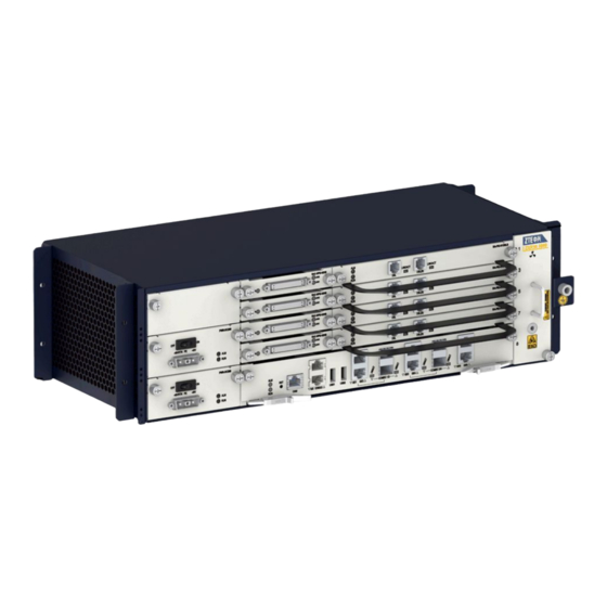
Integrated on the router and cannot be plugged or unplugged. board Boards The ZXR10 2800-3E chassis provides three slots for line interface boards. Power modules The ZXR10 2800-3E chassis provides two slots for one or two power modules. SJ-20150204153047-004|2015-03-30 (R1.0) ZTE Proprietary and Confidential... -
Page 36: Figure 5-1 Front Structure Graph For A Zxr10 2800-3E Chassis
Two Combo interfaces. USB interfaces USB2.0 interfaces, which are used to store applications and other data and support commissioning. Network interface (RJ45) Maintenance network interface (10M/100M/1000M), which is used for system control and application download. SJ-20150204153047-004|2015-03-30 (R1.0) ZTE Proprietary and Confidential... -
Page 37: Slot Deployment
SPIU line of the PIU/SPIU line 5.1.2 Slot Deployment Figure 5-4 shows slots and slot IDs on the back of a ZXR10 2800-3E chassis. Figure 5-4 Slots on the Back of a ZXR10 2800-3E Chassis SJ-20150204153047-004|2015-03-30 (R1.0) ZTE Proprietary and Confidential... -
Page 38: System Parameters
Rated input voltage 100 V AC–240 V AC Range of the input frequency 50 Hz–60 Hz Rated output power 250 W Grounding resistance Grounding resistance with common earthing, which is lower than 5 Ω. SJ-20150204153047-004|2015-03-30 (R1.0) ZTE Proprietary and Confidential... -
Page 39: Power Supplies
Green The power module is operating properly. The power module is operating improperly. Buttons For functions of the power buttons on the AC power module of the ZXR10 2800-3E chassis, refer to Table 5-5. SJ-20150204153047-004|2015-03-30 (R1.0) ZTE Proprietary and Confidential... -
Page 40: Dc Power Module
DC power module of a ZXR10 2800-3E chassis. Figure 5-6 Panel of the DC Power Module Indicators For functions of the indicators on the DC power module of the ZXR10 2800-3E chassis, refer to Table 5-7. SJ-20150204153047-004|2015-03-30 (R1.0) ZTE Proprietary and Confidential... -
Page 41: Table 5-7 Functions Of The Indicators On The Panel Of The Dc Power Module Of The Zxr10 2800-3E Chassis
3.15 in. × 1.57 in. × 6.89 in. (80 mm ×40 mm ×175 mm) depth) Weight 0.52 kg Range of the input voltage From -72 V DC to -38 V DC Rated output power 250 W Rated input current 8.5 A SJ-20150204153047-004|2015-03-30 (R1.0) ZTE Proprietary and Confidential... - Page 42 ZXR10 ZSR V2 Hardware Description This page intentionally left blank. SJ-20150204153047-004|2015-03-30 (R1.0) ZTE Proprietary and Confidential...
-
Page 43: Chapter 6 Zxr10 1800-2E Chassis
Board The ZXR10 1800-2E chassis provides two slots for line interface boards. Power module The ZXR10 1800-2E chassis provides two slots for one or two power modules. SJ-20150204153047-004|2015-03-30 (R1.0) ZTE Proprietary and Confidential... -
Page 44: Figure 6-1 Front View Of A Zxr10 1800-2E Chassis
Two Combo interfaces. USB interfaces USB2.0 interfaces, which are used to store applications and other data and support commissioning. Network interfaces (RJ45) Maintenance network interfaces (10M/100M/1000M), which are used to control the system and download applications. SJ-20150204153047-004|2015-03-30 (R1.0) ZTE Proprietary and Confidential... -
Page 45: Slots
A ZXR10 1800-2E chassis has a structure suitable for horizontal installation. Two service board slots are designed for the chassis, which are numbered as 0-1 in order. Slots 0 and 1 are used to install SPIU interface boards. SJ-20150204153047-004|2015-03-30 (R1.0) ZTE Proprietary and Confidential... -
Page 46: System Parameters
50 Hz–60 Hz, and DC power from -38 V to -72 V. The 1+1 dual-power redundancy mode and power supply swapping are available. The power modules have the following functions: Alarms are generated due to a high or low input or output voltage. SJ-20150204153047-004|2015-03-30 (R1.0) ZTE Proprietary and Confidential... -
Page 47: Ac Power Module
Table 6-5 Functions of the Power Buttons of the AC Power Module of the ZXR10 1800-2E Chassis Button Description ON (—) Dial the button to ON to turn on the module. OFF (O) Dial the button to OFF to turn off the power. SJ-20150204153047-004|2015-03-30 (R1.0) ZTE Proprietary and Confidential... -
Page 48: Dc Power Module
Green The power module is operating properly. The power module is operating improperly. Buttons For functions of the power buttons on the DC power module of the ZXR10 1800-2E chassis, refer to Table 6-8. SJ-20150204153047-004|2015-03-30 (R1.0) ZTE Proprietary and Confidential... -
Page 49: Table 6-8 Functions Of The Power Buttons Of The Dc Power Module Of The Zxr10
3.15 in. × 1.57 in. × 6.89 in. (80 mm ×40 mm ×175 mm) Weight 0.52 kg Range of the input voltage From -72 V DC to -38 V DC Rated output power 250 W Rated input current 8.5 A SJ-20150204153047-004|2015-03-30 (R1.0) ZTE Proprietary and Confidential... - Page 50 ZXR10 ZSR V2 Hardware Description This page intentionally left blank. SJ-20150204153047-004|2015-03-30 (R1.0) ZTE Proprietary and Confidential...
-
Page 51: Chapter 7 Mpfu
SNMP network management system. The MPFU of the ZXR10 2800-3E, ZXR10 1800-2E or ZXR10 1800-2S is integrated into the chassis and cannot be removed. The MPFU boards of the ZXR10 2800-4 and ZXR10 3800-8 can be divided into three types: RAC-2838-MPFU-A, RAC-2838-MPFU-B, and RAC-2838-MPFU-C. -
Page 52: Figure 7-1 Panel Of The Rac-2838-Mpfu-A
Indicator Number Color Description Green The indicator is lit when the board is operating properly. The indicator is lit if the board is not operating properly. LINK/ACT Green Link state indicators of COMBO interfaces. SJ-20150204153047-004|2015-03-30 (R1.0) ZTE Proprietary and Confidential... -
Page 53: Rac-2838-Mpfu-B/Rac-2838-Mpfu-C
Both of them support separation of the forwarding plane and control plane. Panel The RAC-2838-MPFU-B and RAC-2838-MPFU-C have the same overview except the silk screen name. For an overview of the RAC-2838-MPFU-B/RAC-2838-MPFU-C, see Figure 7-2. Figure 7-2 RAC-2838-MPFU-B and RAC-2838-MPFU-C SJ-20150204153047-004|2015-03-30 (R1.0) ZTE Proprietary and Confidential... -
Page 54: Table 7-5 Description Of The Interfaces Of The
Green Link state indicators of COMBO interfaces. Buttons description button panel RAC-2838-MPFU-B/RAC-2838-MPFU-C, refer to Table 7-7. Table 7-7 Description of the RST Button on the Panel of the RAC-2838-MPFU-B/RAC-2838-MPFU-C Button Description Resets the board. SJ-20150204153047-004|2015-03-30 (R1.0) ZTE Proprietary and Confidential... -
Page 55: Table 7-8 Technical Parameters Of The
Specification Silk screen name RAC-2838-MPFU-B/RAC-2838-MPFU-C Dimensions (H × W × D) 11.7 in. × 1.58 in. × 6.9 in. (296.3 mm ×40.24 mm ×175 mm) Power consumption 35 W Weight 2.38 lb. (1.08 kg) SJ-20150204153047-004|2015-03-30 (R1.0) ZTE Proprietary and Confidential... - Page 56 ZXR10 ZSR V2 Hardware Description This page intentionally left blank. SJ-20150204153047-004|2015-03-30 (R1.0) ZTE Proprietary and Confidential...
-
Page 57: Chapter 8 General Processing Boards
For the panel of the RAC-DPIU-OSU-A1 board of the general processing board, see Figure 8-1. Figure 8-1 Panel of an RAC-DPIU-OSU-A1 Board Interfaces For a description of interfaces on the RAC-DPIU-OSU-A1 board, refer to Table 8-1. SJ-20150204153047-004|2015-03-30 (R1.0) ZTE Proprietary and Confidential... -
Page 58: Table 8-1 Descriptions Of Interfaces On The Rac-Dpiu-Osu-A1 Board
7.76 in. × 1.58 in. × 6.9 in. (197.2 mm ×40.24 mm ×175 mm) Power consumption 40 W Weight 2.71 lb. (1.23 kg) Memory Default capacity (byte) 4 G or 8 G (optional) Hard disk Default capacity (byte) 500 G or 1 T (optional) SJ-20150204153047-004|2015-03-30 (R1.0) ZTE Proprietary and Confidential... -
Page 59: Rac-Dpiu-Osu-A2
VGA interface (DB15) X86 VGA output interface. USB interfaces USB2.0 interfaces used to install the X86 system. Indicator The RAC-DPIU-OSU-A2 board provides multiple LED indicators on its panel. For their functions, refer to Table 8-6. SJ-20150204153047-004|2015-03-30 (R1.0) ZTE Proprietary and Confidential... -
Page 60: Rac-Dpiu-Fw-A
Classifies, monitors, filters, and transfers received messages depending on applications. Provides four lines of high-speed serial interfaces for the internal gigabit Ethernet and one line of electrical interface for the external gigabit Ethernet. GE electrical interfaces support 10BASE-T/100BASE-TX/1000BASE-T. SJ-20150204153047-004|2015-03-30 (R1.0) ZTE Proprietary and Confidential... -
Page 61: Figure 8-3 Panel Of An Rac-Dpiu-Fw-A Board
An RAC-DPIU-FW-A board has two buttons on its panel. For their functions, refer to Table 8-11. Table 8-11 Functions of Buttons on the Panel of an RAC-DPIU-FW-A Board Button Description Board reset button. Board power button. SJ-20150204153047-004|2015-03-30 (R1.0) ZTE Proprietary and Confidential... -
Page 62: Table 8-12 Technical Parameters Of An Rac-Dpiu-Fw-A Board
7.76 in. × 1.58 in. × 6.9 in. (197.2 mm ×40.24 mm ×175 mm) Power consumption 35 W Weight 2.31 lb. (1.05 kg) Memory Default capacity (byte) 4 G or 8 G (optional) Hard disk Default capacity (byte) SJ-20150204153047-004|2015-03-30 (R1.0) ZTE Proprietary and Confidential... -
Page 63: Chapter 9 Line Interface Boards
The DPIU is a fast-speed interface board, and the PIU and SPIU are common-speed interface boards. The ZXR10 2800-4 and ZXR10 3800-8 support the combination of different types of line interface boards. Table of Contents RAC-SPIU-02CE1-75 ....................9-2 RAC-SPIU-02UE1-75 ....................9-3 RAC-SPIU-02CE1-120 ....................9-5 RAC-SPIU-02UE1-120 ....................9-6 RAC-SPIU-02HS ......................9-8 SJ-20150204153047-004|2015-03-30 (R1.0) ZTE Proprietary and Confidential... -
Page 64: Rac-Spiu-02Ce1-75
Supports the processing of various services, such as and ML-PPP. Supports hot swapping. Supports board information query and temperature monitoring. Panel For the panel of the RAC-SPIU-02CE1-75 board, see Figure 9-1. Figure 9-1 Front Panel of the RAC-SPIU-02CE1-75 Board SJ-20150204153047-004|2015-03-30 (R1.0) ZTE Proprietary and Confidential... -
Page 65: Rac-Spiu-02Ue1-75
Dimensions (W ×H × D) 3.86 in. × 0.79 in. × 6.9 in. (98.1 mm ×19.92 mm ×175 mm) Power consumption Weight 0.53 lb. (0.24 kg) Rate 2.048 Mbps×2 9.2 RAC-SPIU-02UE1-75 Overview RAC-SPIU-02UE1-75 board provides the following functions: SJ-20150204153047-004|2015-03-30 (R1.0) ZTE Proprietary and Confidential... -
Page 66: Figure 9-2 Front Panel Of The Rac-Spiu-02Ue1-75 Board
The indicator is lit when the link is operating properly, and is LNK1/LNK2 Green not lit when the link is idle. Technical Parameters For the technical parameters of the RAC-SPIU-02UE1-75 board, refer to Table 9-7. SJ-20150204153047-004|2015-03-30 (R1.0) ZTE Proprietary and Confidential... -
Page 67: Rac-Spiu-02Ce1-120
The RAC-SPIU-02CE1-120 board provides RJ48 interfaces, and it only supports 120 ohm E1 interfaces. For a description of the interface properties, refer to Table 9-8. Table 9-8 Interface Properties of the RAC-SPIU-02CE1-120 Board Property Description Connector type RJ48 SJ-20150204153047-004|2015-03-30 (R1.0) ZTE Proprietary and Confidential... -
Page 68: Rac-Spiu-02Ue1-120
Restores the line clock and providing it to an MPFU board for reference. Supports the processing of various services, such as and ML-PPP. Supports hot swapping. Supports board information query and temperature monitoring. Supports the delayed power-on function. SJ-20150204153047-004|2015-03-30 (R1.0) ZTE Proprietary and Confidential... -
Page 69: Figure 9-4 Front Panel Of The Rac-Spiu-02Ue1-120 Board
Table 9-13 Technical Parameters of the RAC-SPIU-02UE1-120 Board Parameter Specification Silk screen name RAC-SPIU-02UE1-120 Dimensions (W ×H × D) 3.86 in. × 0.79 in. × 6.9 in. (98.1 mm ×19.92 mm ×175 mm) Power consumption Weight 0.53 lb. (0.24 kg) SJ-20150204153047-004|2015-03-30 (R1.0) ZTE Proprietary and Confidential... -
Page 70: Rac-Spiu-02Hs
Table 9-14. Table 9-14 Interface Properties of the RAC-SPIU-02HS Board Property Description Connector type DB50 Operational mode Asynchronous or synchronous Applied standard V.24, V.35, X.21, or RS232 Supported link protocol PPP, HDLC, and FR SJ-20150204153047-004|2015-03-30 (R1.0) ZTE Proprietary and Confidential... -
Page 71: Rac-Spiu-04Ge
Provides four lines of electrical interfaces for gigabit Ethernet interface cards. Supports self-adaptive 10/100/1000BASE-T. Supports hop swapping of boards. Supports board temperature detection and board ID read. Panel For the panel of an RAC-SPIU-04GE board, see Figure 9-6. SJ-20150204153047-004|2015-03-30 (R1.0) ZTE Proprietary and Confidential... -
Page 72: Figure 9-6 Front Panel Of An Rac-Spiu-04Ge Board
Table 9-19 Technical Parameters of an RAC-SPIU-04GE Board Parameter Description Board name silk screen RAC-SPIU-04GE Dimension (width × height × 3.86 in. × 0.79 in. × 6.9 in. (98.1 mm ×19.92 mm ×175 mm) depth) 9-10 SJ-20150204153047-004|2015-03-30 (R1.0) ZTE Proprietary and Confidential... -
Page 73: Rac-Piu-Lte
Mbps. For WCDMA HSDPA, the board supports network speeds of 21 Mbps and 5.76 à Mbps. Supports hot-swapping. Panel Figure 9-7 shows the panel of the RAC-PIU-LTE board. Figure 9-7 RAC-PIU-LTE Board Panel 9-11 SJ-20150204153047-004|2015-03-30 (R1.0) ZTE Proprietary and Confidential... -
Page 74: Table 9-20 Rac-Piu-Lte Board Indicator Descriptions
3G signal indicator. It is on after the board accesses a 3G network. Green LTE signal indicator. It is on after the board accesses an LTE network. Technical Specifications For a description of the technical specifications of the RAC-PIU-LTE board, refer to Table 9-21. 9-12 SJ-20150204153047-004|2015-03-30 (R1.0) ZTE Proprietary and Confidential... -
Page 75: Rac-Piu-01Dslb
For a description of the interface properties, refer to Table 9-22. Table 9-22 Interface Properties of the RAC-PIU-01DSLB Board Property Description Connector type RJ-11 interface, which can be connected to a DSLAM through a common telephone cable 9-13 SJ-20150204153047-004|2015-03-30 (R1.0) ZTE Proprietary and Confidential... -
Page 76: Table 9-23 Description Of The Indicators On The Panel Of The Rac-Piu-01Dslb Board
Silk screen name RAC-PIU-01DSLB Dimensions (W × H × D) 7.76 in. × 0.79 in. × 6.9 in. (197.2 mm ×19.92 mm ×175 mm) Power consumption 16 W Weight 0.88 lb. (0.4 kg) 9-14 SJ-20150204153047-004|2015-03-30 (R1.0) ZTE Proprietary and Confidential... -
Page 77: Rac-Piu-04Shdsl
Table 9-25. Table 9-25 Interface Properties of the RAC-PIU-04SHDSL Board Property Description Connector type RJ45 interface, connected to four RJ11 interfaces at the peer end Operational mode Full duplex Applied standard ITU-T G.991.2 9-15 SJ-20150204153047-004|2015-03-30 (R1.0) ZTE Proprietary and Confidential... -
Page 78: Rac-Piu-04Hs
For synchronous data transmission mode, the ports can be connected to DTEs à or DCEs. The circuit side supports the V.24, V.35, or X.21 interfaces. The V.24 interface supports a maximum rate of 115.2 Kbps. The V.35 interface supports 9-16 SJ-20150204153047-004|2015-03-30 (R1.0) ZTE Proprietary and Confidential... -
Page 79: Figure 9-10 Front Panel Of The Rac-Piu-04Hs Board
The indicator is lit when the link is operating properly, and is LNK1–LNK4 Green not lit when the link is idle. Technical Parameters For the technical parameters of the RAC-PIU-04HS board, refer to Table 9-30. 9-17 SJ-20150204153047-004|2015-03-30 (R1.0) ZTE Proprietary and Confidential... -
Page 80: Rac-Piu-04Ce1-75
E1 interfaces. For a description of the interface properties, refer to Table 9-31. Table 9-31 Interface Properties of the RAC-PIU-04CE1-75 Board Property Description Connector type Micro coaxial Operational mode Full duplex Applied standard ITU-T G.703, G.704 Supported link protocol PPP, ML-PPP, HDLC, 9-18 SJ-20150204153047-004|2015-03-30 (R1.0) ZTE Proprietary and Confidential... -
Page 81: Rac-Piu-04Ce1-120
Supports the processing of various services, such as and ML-PPP. Supports hot swapping. Supports board information query and temperature monitoring. Supports the delayed power-on function. Panel For the panel of the RAC-PIU-04CE1-120 board, see Figure 9-12. 9-19 SJ-20150204153047-004|2015-03-30 (R1.0) ZTE Proprietary and Confidential... -
Page 82: Figure 9-12 Front Panel Of The Rac-Piu-04Ce1-120 Board
Dimensions (W × H × D) 7.76 in. × 0.79 in. × 6.9 in. (197.2 mm ×19.92 mm ×175 mm) Power consumption 11 W Weight 1.19 lb. (0.54 kg) Rate 2.048 Mbps × 4 9-20 SJ-20150204153047-004|2015-03-30 (R1.0) ZTE Proprietary and Confidential... -
Page 83: Rac-Piu-04Ue1-75
Table 9-38 Description of the Indicators on the Panel of the RAC-PIU-04UE1-75 Board Indicator Color Description Green The indicator is lit when the board is operating properly. The indicator is lit if the board produces an alarm. 9-21 SJ-20150204153047-004|2015-03-30 (R1.0) ZTE Proprietary and Confidential... -
Page 84: Rac-Piu-04Ue1-120
Figure 9-14 Front Panel of the RAC-PIU-04UE1-120 Board Interface Property The RAC-PIU-04UE1-120 board provides RJ48 interfaces, and it only supports 120 ohm E1 interfaces. For a description of the interface properties, refer to Table 9-40. 9-22 SJ-20150204153047-004|2015-03-30 (R1.0) ZTE Proprietary and Confidential... -
Page 85: Rac-Piu-16Ce1
1.19 lb. (0.54 kg) Rate 2.048 Mbps × 4 9.15 RAC-PIU-16CE1 Overview RAC-PIU-16CE1 board provides the following functions: Provides 16 channelized/unchannelized E1 interfaces. Supports the processing of various services, such as and ML-PPP. Supports hot swapping. 9-23 SJ-20150204153047-004|2015-03-30 (R1.0) ZTE Proprietary and Confidential... -
Page 86: Figure 9-15 Front Panel Of The Rac-Piu-16Ce1 Board
Operational mode Full duplex Applied standard ITU-T G.703, G.704 Supported link protocol PPP, ML-PPP, HDLC, Supported network protocol Indicators For a description of the indicators of the RAC-PIU-16CE1 board, refer to Table 9-44. 9-24 SJ-20150204153047-004|2015-03-30 (R1.0) ZTE Proprietary and Confidential... -
Page 87: Rac-Piu-16Ce1-Ces
Panel For the panel of the RAC-PIU-16CE1-CES board, see Figure 9-16. Figure 9-16 Front Panel of the RAC-PIU-16CE1-CES Board Interface Properties For the interface properties of the RAC-PIU-16CE1-CES board, refer to Table 9-46. 9-25 SJ-20150204153047-004|2015-03-30 (R1.0) ZTE Proprietary and Confidential... -
Page 88: Rac-Piu-01P12-Sfp
Supports 1-wire OC-12/STM-4 applications. Supports the processing of various services, such as and HDLC. Supports hot swapping. Supports board information query and temperature monitoring. Panel For the panel of the RAC-PIU-01P12-SFP board, see Figure 9-17. 9-26 SJ-20150204153047-004|2015-03-30 (R1.0) ZTE Proprietary and Confidential... -
Page 89: Figure 9-17 Front Panel Of The Rac-Piu-01P12-Sfp Board
Table 9-51 Technical Parameters of the RAC-PIU-01P12-SFP Board Parameter Specification Silk screen name RAC-PIU-01P12-SFP Dimensions (W × H × D) 7.76 in. × 0.79 in. × 6.9 in. (197.2 mm ×19.92 mm ×175 mm) Power consumption 16 W 9-27 SJ-20150204153047-004|2015-03-30 (R1.0) ZTE Proprietary and Confidential... -
Page 90: Rac-Piu-02P3-Sfp
Operational mode Full duplex Applied standard SONET GR-253-CORE/ITU-T G.707 Supported link protocol PPP, HDLC, FR, POSGROUP Supported network protocol Indicators For a description of the indicators of the RAC-PIU-02P3-SFP board, refer to Table 9-53. 9-28 SJ-20150204153047-004|2015-03-30 (R1.0) ZTE Proprietary and Confidential... -
Page 91: Rac-Piu-04P3-Sfp
Supports the processing of various services, such as and HDLC. Supports hot swapping. Supports board information query and temperature monitoring. Panel For the panel of the RAC-PIU-04P3-SFP board, see Figure 9-19. Figure 9-19 Front Panel of the RAC-PIU-04P3-SFP Board 9-29 SJ-20150204153047-004|2015-03-30 (R1.0) ZTE Proprietary and Confidential... -
Page 92: Table 9-55 Interface Properties Of The Rac-Piu-04P3-Sfp Board
Dimensions (W × H × D) 7.76 in. × 0.79 in. × 6.9 in. (197.2 mm ×19.92 mm ×175 mm) Power consumption 18 W Weight 1.19 lb. (0.54 kg) Rate 155.52 Mbps × 4 9-30 SJ-20150204153047-004|2015-03-30 (R1.0) ZTE Proprietary and Confidential... -
Page 93: Rac-Piu-02Cp3-Sfp
Table 9-59 Description of the Indicators on the Panel of the RAC-PIU-02CP3-SFP Board Indicator Color Description Green The indicator is lit when the board is operating properly. The indicator is lit if the board produces an alarm. 9-31 SJ-20150204153047-004|2015-03-30 (R1.0) ZTE Proprietary and Confidential... -
Page 94: Rac-Piu-04Cp3-Sfp
Supports the processing of various services, such as and HDLC. Supports hot swapping. Supports board information query and temperature monitoring. Panel For the panel of the RAC-PIU-04CP3-SFP board, see Figure 9-21. Figure 9-21 Front Panel of the RAC-PIU-04CP3-SFP Board 9-32 SJ-20150204153047-004|2015-03-30 (R1.0) ZTE Proprietary and Confidential... -
Page 95: Table 9-61 Interface Properties Of The Rac-Piu-04Cp3-Sfp Board
Dimensions (W × H × D) 7.76 in. × 0.79 in. × 6.9 in. (197.2 mm ×19.92 mm ×175 mm) Power consumption 18 W Weight 1.19 lb. (0.54 kg) Rate 155.52 Mbps × 4 9-33 SJ-20150204153047-004|2015-03-30 (R1.0) ZTE Proprietary and Confidential... -
Page 96: Rac-Piu-04Ge-Sfp
Table 9-65 Description of the Indicators on the Panel of the RAC-PIU-04GE-SFP Board Indicator Color Description Green The indicator is lit when the board is operating properly. The indicator is lit if the board produces an alarm. 9-34 SJ-20150204153047-004|2015-03-30 (R1.0) ZTE Proprietary and Confidential... -
Page 97: Rac-Piu-08Ge-Sfp
For the panel of the RAC-PIU-08GE-SFP board, see Figure 9-23. Figure 9-23 Front Panel of the RAC-PIU-08GE-SFP Board Interface Properties The RAC-PIU-08GE-SFP board uses SFP optical modules. For a description of the interface properties, refer to Table 9-67. 9-35 SJ-20150204153047-004|2015-03-30 (R1.0) ZTE Proprietary and Confidential... -
Page 98: Rac-Piu-05Ge-4E1Sfp
7.76 in. × 0.79 in. × 6.9 in. (197.2 mm ×19.92 mm ×175 mm) Power consumption 15 W Weight 1.19 lb. (0.54 kg) Rate 1 GE × 8 9.24 RAC-PIU-05GE-4E1SFP Overview RAC-PIU-05GE-4E1SFP board provides the following functions: 9-36 SJ-20150204153047-004|2015-03-30 (R1.0) ZTE Proprietary and Confidential... -
Page 99: Figure 9-24 Front Panel Of The Rac-Piu-05Ge-4E1Sfp Board
Table 9-71 Optical Interface Properties of the RAC-PIU-05GE-4E1SFP Board Property Description Connector type LC-type SFP optical module interface Operational mode Full duplex Applied standard IEEE 802.3z Gigabit Ethernet standard Supported frame format Ethernet frame 9-37 SJ-20150204153047-004|2015-03-30 (R1.0) ZTE Proprietary and Confidential... -
Page 100: Table 9-72 Description Of The Indicators On The Panel Of The Rac-Piu-05Ge-4E1Sfp Board
Dimensions (W × H × D) 7.76 in. × 0.79 in. × 6.9 in. (197.2 mm ×19.92 mm ×175 mm) Power consumption 11 W Weight 0.88 lb. (0.4 kg) Rate 1 GE × 5 9-38 SJ-20150204153047-004|2015-03-30 (R1.0) ZTE Proprietary and Confidential... -
Page 101: Rac-Piu-09Ge-8E1Sfp
The RAC-PIU-09GE-8E1SFP board uses SFP optical modules. For a description of the optical interface properties, refer to Table 9-75. Table 9-75 Optical Interface Properties of the RAC-PIU-09GE-8E1SFP Board Property Description Connector type LC-type SFP optical module interface 9-39 SJ-20150204153047-004|2015-03-30 (R1.0) ZTE Proprietary and Confidential... -
Page 102: Table 9-76 Description Of The Indicators On The Panel Of The Rac-Piu-09Ge-8E1Sfp Board
Dimensions (W × H × D) 7.76 in. × 0.79 in. × 6.9 in. (197.2 mm ×19.92 mm ×175 mm) Power consumption 12 W Weight 1.19 lb. (0.54 kg) Rate 1 GE × 9 9-40 SJ-20150204153047-004|2015-03-30 (R1.0) ZTE Proprietary and Confidential... -
Page 103: Rac-Piu-08Fe1Ge-1Sfp
The RAC-PIU-08FE1GE-1SFP board uses SFP optical modules. For a description of the optical interface properties, refer to Table 9-79. Table 9-79 Optical Interface Properties of the RAC-PIU-08FE1GE-1SFP Board Property Description Connector type LC-type SFP optical module interface 9-41 SJ-20150204153047-004|2015-03-30 (R1.0) ZTE Proprietary and Confidential... -
Page 104: Table 9-80 Description Of The Indicators On The Panel Of The Rac-Piu-08Fe1Ge-1Sfp Board
Dimensions (W × H × D) 7.76 in. × 0.79 in. × 6.9 in. (197.2 mm ×19.92 mm ×175 mm) Power consumption 11 W Weight 1.19 lb. (0.54 kg) Rate 1 GE × 1, 1FE × 8 9-42 SJ-20150204153047-004|2015-03-30 (R1.0) ZTE Proprietary and Confidential... -
Page 105: Rac-Dpiu-16Ge-12Sfp4E
Applied standard IEEE 802.3z Gigabit Ethernet standard Supported frame format Ethernet frame Supported network protocol The RAC-DPIU-16GE-12SFP4E board uses SFP optical modules. For a description of the optical interface properties, refer to Table 9-83. 9-43 SJ-20150204153047-004|2015-03-30 (R1.0) ZTE Proprietary and Confidential... -
Page 106: Table 9-83 Optical Interface Properties Of The Rac-Dpiu-16Ge-12Sfp4E Board
Parameter Specification Silk screen name RAC-DPIU-16GE-12SFP4E Dimensions (W × H × D) 7.76 in. × 1.58 in. × 6.9 in. (197.2 mm ×40.24 mm ×175 mm) Power consumption 36 W Weight 0.6 kg 9-44 SJ-20150204153047-004|2015-03-30 (R1.0) ZTE Proprietary and Confidential... -
Page 107: Rac-Dpiu-01Xge-Sfp
Table 9-86 Interface Properties of the RAC-DPIU-01XGE-SFP+ Board Property Description Connector type Optical interface property Determined by the attributes of the selected SFP+ optical module Operational mode Full duplex Applied standard IEEE802.3ae Supported link protocol Ethernet frame/SONET/SDH Supported network protocol 9-45 SJ-20150204153047-004|2015-03-30 (R1.0) ZTE Proprietary and Confidential... -
Page 108: Table 9-87 Description Of The Indicators On The Panel Of The Rac-Dpiu-01Xge-Sfp+ Board
Silk screen name RAC-DPIU-01XGE-SFP+ Dimensions (H × W × D) 0.78 in. × 7.77 in. × 6.9 in (19.92 mm × 197.2 mm × 175 mm) Power consumption 16 W Weight 0.68 kg Rate 10G×1 9-46 SJ-20150204153047-004|2015-03-30 (R1.0) ZTE Proprietary and Confidential... -
Page 109: Chapter 10 Cables
Power Cables and Grounding Cables...............10-1 Signal Cables ......................10-4 10.1 Power Cables and Grounding Cables 10.1.1 DC Power Cables A DC power cable of the ZXR10 ZSR V2 is a black/blue fire-retardant PVC insulated cable, Figure 10-1. 10-1 SJ-20150204153047-004|2015-03-30 (R1.0) ZTE Proprietary and Confidential... -
Page 110: Figure 10-1 Dc Power Cable
1. D-type 3-core straight 2. 12 A WG blue multi-strand 4. Pre-insulated tube terminal solder connector (hole + heat-resistant cable pin + hole, with protective 3. 12 A WG black UL1015 edges) cable 10-2 SJ-20150204153047-004|2015-03-30 (R1.0) ZTE Proprietary and Confidential... -
Page 111: Ac Power Cables
Table 10-3 Technical Parameters of an AC Power Cable Item Description Terminal model 10 A international standard 3-pin flat male plug 10 A international standard T-shaped female plug Cable model 3 × 0.0012 sq. in. (0.75 mm ), with 3C certification 10-3 SJ-20150204153047-004|2015-03-30 (R1.0) ZTE Proprietary and Confidential... -
Page 112: Grounding Cables
Table 10-4 Core Wires of an AUX Cable RJ45 PCB AUX Signal DB9 Pin PC DB9 (Hole) Modem DB-9 Modem DB-9 Signal Direction Signal (Pin) Pin (Pin) Signal ← → → ← — ← 10-4 SJ-20150204153047-004|2015-03-30 (R1.0) ZTE Proprietary and Confidential... -
Page 113: Console Cables
Table 10-5 Core Wires of a Console Cable RJ45 Pin PCB CONSOLE Signal DB9 Pin PC DB9 (Hole) Signal Direction Signal No signal in case of ← three wires No signal in case of → three wires → ← 10-5 SJ-20150204153047-004|2015-03-30 (R1.0) ZTE Proprietary and Confidential... -
Page 114: Ethernet Cables
Ethernet cable, see Figure 10-6. Figure 10-6 Ethernet cable 1. Ethernet cable connector 2. Standard shielded Ethernet 3. Cable label cable For the wiring sequence of the straight-through Ethernet cable, refer to Table 10-6. 10-6 SJ-20150204153047-004|2015-03-30 (R1.0) ZTE Proprietary and Confidential... -
Page 115: Optical Fibers
10.2.4 Optical Fibers Overview The optical fiber is a communication medium that uses a bundle of thin glass rods to transmit the modulated light. There are two types of optical fibers, single-mode optical 10-7 SJ-20150204153047-004|2015-03-30 (R1.0) ZTE Proprietary and Confidential... -
Page 116: Figure 10-7 Optical Fiber Cross-Sectional Area
For the connector pairing and usage, refer to Table 10-9. Table 10-9 Optical Fiber Connector Pairing and Usage Device-end Opposite-end Cable Type Cable Usage Connector type Connector type Single-mode Connection between a device indoor optical fiber interface line card and 10-8 SJ-20150204153047-004|2015-03-30 (R1.0) ZTE Proprietary and Confidential... -
Page 117: Shdsl Cables
For an overview of the SHDSL cable, see Figure 10-9. Figure 10-9 SHDSL Cable 1. RJ45 connector 2. Eight-core CAT5e 100-ohm 3. RJ11 connector non-shielded twisted pair cable 10-9 SJ-20150204153047-004|2015-03-30 (R1.0) ZTE Proprietary and Confidential... -
Page 118: Table 10-10 Wiring Sequence Of The Shdsl Cable
V.35/V.24 DTE cable (RA-DTE-DB50-34pole): A 34pole male connector is used at the network end. V.35/V.24 DCE cable (RA-DCE-DB50-34pole): A 34pole female connector is used at the network end. For an overview of the V.35/V.24 DTE cable (RA-DTE-DB50-DB25), see Figure 10-10. 10-10 SJ-20150204153047-004|2015-03-30 (R1.0) ZTE Proprietary and Confidential... -
Page 119: Figure 10-10 V.35/V.24 Dte Cable (Ra-Dte-Db50-Db25)
For an overview of the V.35/V.24 DCE cable (RA-DCE-DB50-DB25), see Figure 10-11. Figure 10-11 V.35/V.24 DCE Cable (RA-DCE-DB50-DB25) 1. Device-end connector 2. Network-end connector DB50 DB25 (female) For an overview of the V.35/V.24 DTE cable (RA-DTE-DB50-34pole), see Figure 10-12. 10-11 SJ-20150204153047-004|2015-03-30 (R1.0) ZTE Proprietary and Confidential... -
Page 120: Figure 10-12 V.35/V.24 Dte Cable (Ra-Dte-Db50-34Pole)
For an overview of the V.35/V.24 DCE cable (RA-DCE-DB50-34pole), see Figure 10-13. Figure 10-13 V.35/V.24 DCE Cable (RA-DCE-DB50-34pole) 1. Device-end connector 2. Network-end connector DB50 34pole (female) For a description of the synchronous/asynchronous serial cable types, refer to Table 10-12. 10-12 SJ-20150204153047-004|2015-03-30 (R1.0) ZTE Proprietary and Confidential... -
Page 121: Synchronous/Asynchronous Serial Cable
DB50 Sixteen twisted-pair cables in two groups, twisted-pair cable connected to the connectors as required 75 Ω Unbalanced Coaxial Cable For an overview of the 75 Ω unbalanced coaxial cable, see Figure 10-14. 10-13 SJ-20150204153047-004|2015-03-30 (R1.0) ZTE Proprietary and Confidential... -
Page 122: Figure 10-14 75 Ω Unbalanced Coaxial Cable
Signal Micro-Coaxial A) A-1 core A-1 shield R1– A-2 core A-2 shield T1– A-3 core A-3 shield R2– A-4 core A-4 shield T2– A-5 core A-5 shield R3– A-6 core A-6 shield T3– 10-14 SJ-20150204153047-004|2015-03-30 (R1.0) ZTE Proprietary and Confidential... -
Page 123: Table 10-15 Correspondence Relationships Between The End-A Pins And End-B2 Cores Of The 75 Ω Unbalanced Coaxial Cable
B-6 core B-6 shield T7– B-7 core B-7 shield R8– B-8 core B-8 shield T8– 120 Ω Balanced Twisted-Pair Cable For an overview of the 120 Ω balanced twisted-pair cable, see Figure 10-15. 10-15 SJ-20150204153047-004|2015-03-30 (R1.0) ZTE Proprietary and Confidential... -
Page 124: Figure 10-15 120 Ω Balanced Twisted-Pair Cable
Blue Twisted pair White R1– Orange Twisted pair White T1– Green Twisted pair White R2– Brown Twisted pair White T2– Grey Twisted pair White R3– Blue Twisted pair T3– Orange Twisted pair R4– 10-16 SJ-20150204153047-004|2015-03-30 (R1.0) ZTE Proprietary and Confidential... -
Page 125: Table 10-17 Correspondence Relationships Between The End-A Pins And End-B2 Cores Of The 120 Ω Balanced Twisted-Pair Cable
R5– Orange Twisted pair White T5– Green Twisted pair White R6– Brown Twisted pair White T6– Grey Twisted pair White R7– Blue Twisted pair T7– Orange Twisted pair R8– Green Twisted pair T8– 10-17 SJ-20150204153047-004|2015-03-30 (R1.0) ZTE Proprietary and Confidential... - Page 126 ZXR10 ZSR V2 Hardware Description This page intentionally left blank. 10-18 SJ-20150204153047-004|2015-03-30 (R1.0) ZTE Proprietary and Confidential...
-
Page 127: Appendix A Board Quick Table (Weight And Power Consumption
1.19 lb. (0.54 kg) 11 W RAC-PIU-04UE1-120 1.19 lb. (0.54 kg) 11 W RAC-PIU-16CE1 1.19 lb. (0.54 kg) 16 W RAC-PIU-16CE1-CES 1.19 lb. (0.54 kg) 16 W RAC-PIU-01P12-SFP 1.19 lb. (0.54 kg) 16 W SJ-20150204153047-004|2015-03-30 (R1.0) ZTE Proprietary and Confidential... - Page 128 0.88 lb. (0.4 kg) 11 W RAC-PIU-09GE-8E1SFP 1.19 lb. (0.54 kg) 12 W RAC-PIU-08FE1GE-1SFP 1.19 lb. (0.54 kg) 11 W RAC-DPIU-16GE-12SFP4E 1.32 lb. (0.6 kg) 36 W RAC-DPIU-01XGE-SFP+ 1.50 lb. (0.68 kg) 16 W SJ-20150204153047-004|2015-03-30 (R1.0) ZTE Proprietary and Confidential...
-
Page 129: Appendix B Optical Modules Quick Table
Table B-3 155 M SFP Attributes Attribute Parameters Transmission distance (km) Central wavelength 1310 1310 1310 1550 1310 (nm) Reference wavelength 1260~1570 1261~1360 1263~1360 1480~1580 1480~1580 range (nm) Transmitting optical -19~-14 -15~-8 -5~0 -5~0 power range (dBm) SJ-20150204153047-004|2015-03-30 (R1.0) ZTE Proprietary and Confidential... -
Page 130: Table B-4 622 M Sfp Attributes
For the attributes of an 1.25 G SFP optical module, refer to Table B-5. Table B-5 1.25 G SFP Attributes Attribute Parameters Transmission distance (km) Central wavelength 1310 1310 1550 1550 1550 (nm) Reference 770~860 1260~136 1260~136 1480~158 1480~158 1480~158 wavelength range (nm) SJ-20150204153047-004|2015-03-30 (R1.0) ZTE Proprietary and Confidential... - Page 131 -5~0 -2~5 power range (dBm) Receiving sensitivity (dBm) Overload optical power (dBm) Fiber type Multi mode Single Single Single Single Single mode mode mode mode mode Interface type LC-SFP LC-SFP LC-SFP LC-SFP LC-SFP LC-SFP SJ-20150204153047-004|2015-03-30 (R1.0) ZTE Proprietary and Confidential...
- Page 132 ZXR10 ZSR V2 Hardware Description This page intentionally left blank. SJ-20150204153047-004|2015-03-30 (R1.0) ZTE Proprietary and Confidential...
-
Page 133: Figures
Figure 4-2 ZXR10 1800-2S Front Panel ..............4-2 Figure 4-3 ZXR10 1800-2S Rear Panel ..............4-3 Figure 4-4 Front View of the ZXR10 1800-2S Chassis ..........4-4 Figure 4-5 Power Button ................... 4-6 Figure 5-1 Front Structure Graph for a ZXR10 2800-3E Chassis....... 5-2 Figure 5-2 Front Panel of a ZXR10 2800-3E Chassis.......... - Page 134 Figure 10-3 Overview of a Protective Grounding Cable........... 10-4 Figure 10-4 AUX Cable (DB9)................. 10-4 Figure 10-5 Console Cable Structure ..............10-5 Figure 10-6 Ethernet cable..................10-6 Figure 10-7 Optical Fiber Cross-sectional Area............10-8 SJ-20150204153047-004|2015-03-30 (R1.0) ZTE Proprietary and Confidential...
- Page 135 Figure 10-11 V.35/V.24 DCE Cable (RA-DCE-DB50-DB25)........10-11 Figure 10-12 V.35/V.24 DTE Cable (RA-DTE-DB50-34pole) ......... 10-12 Figure 10-13 V.35/V.24 DCE Cable (RA-DCE-DB50-34pole)......... 10-12 Figure 10-14 75 Ω Unbalanced Coaxial Cable ............10-14 Figure 10-15 120 Ω Balanced Twisted-Pair Cable..........10-16 SJ-20150204153047-004|2015-03-30 (R1.0) ZTE Proprietary and Confidential...
- Page 136 Figures This page intentionally left blank. SJ-20150204153047-004|2015-03-30 (R1.0) ZTE Proprietary and Confidential...
-
Page 137: Tables
2800-4 ..................... 3-6 Table 3-9 ZXR10 2800-4 Fan Specifications ............. 3-6 Table 4-1 Descriptions of the Main Components of the ZXR10 1800-2S ....4-1 Table 4-2 ZXR10 1800-2S Front Panel Descriptions ..........4-2 Table 4-3 ZXR10 1800-2S Rear Panel Descriptions..........4-4 SJ-20150204153047-004|2015-03-30 (R1.0) - Page 138 ZXR10 ZSR V2 Hardware Description Table 4-4 System Parameters of the ZXR10 1800-2S ..........4-5 Table 4-5 Power Button Description for the ZXR10 1800-2S AC Power Supply Module..................... 4-6 Table 4-6 Technical Parameters of the AC Power Rectifier of the ZXR10 1800-2S ....................
- Page 139 Table 9-5 Interface Properties of the RAC-SPIU-02UE1-75 Board ......9-4 Table 9-6 Description of the Indicators on the Panel of the RAC-SPIU-02UE1-75 Board ....................... 9-4 Table 9-7 Technical Parameters of the RAC-SPIU-02UE1-75 Board ......9-5 SJ-20150204153047-004|2015-03-30 (R1.0) ZTE Proprietary and Confidential...
- Page 140 Table 9-33 Technical Parameters of the RAC-PIU-04CE1-75 Board......9-19 Table 9-34 Interface Properties of the RAC-PIU-04CE1-120 Board......9-20 Table 9-35 Description of the Indicators on the Panel of the RAC-PIU-04CE1-120 Board ..................... 9-20 VIII SJ-20150204153047-004|2015-03-30 (R1.0) ZTE Proprietary and Confidential...
- Page 141 Table 9-61 Interface Properties of the RAC-PIU-04CP3-SFP Board ......9-33 Table 9-62 Description of the Indicators on the Panel of the RAC-PIU-04CP3-SFP Board ..................... 9-33 Table 9-63 Technical Parameters of the RAC-PIU-04CP3-SFP Board..... 9-33 SJ-20150204153047-004|2015-03-30 (R1.0) ZTE Proprietary and Confidential...
- Page 142 RAC-DPIU-16GE-12SFP4E Board............9-44 Table 9-85 Technical Parameters of the RAC-DPIU-16GE-12SFP4E Board.... 9-44 Table 9-86 Interface Properties of the RAC-DPIU-01XGE-SFP+ Board....9-45 Table 9-87 Description of the Indicators on the Panel of the RAC-DPIU-01XGE-SFP+ Board............. 9-46 SJ-20150204153047-004|2015-03-30 (R1.0) ZTE Proprietary and Confidential...
- Page 143 Table B-1 SFP Optical Modules ................B-1 Table B-2 Optical Module Indicator Descriptions ............B-1 Table B-3 155 M SFP Attributes ................B-1 Table B-4 622 M SFP Attributes ................B-2 Table B-5 1.25 G SFP Attributes ................B-2 SJ-20150204153047-004|2015-03-30 (R1.0) ZTE Proprietary and Confidential...
- Page 144 Tables This page intentionally left blank. SJ-20150204153047-004|2015-03-30 (R1.0) ZTE Proprietary and Confidential...
-
Page 145: Glossary
- Institute of Electrical and Electronics Engineers - Internet Protocol ITU-T - International Telecommunication Union - Telecommunication Standardization Sector ML-PPP - Multilink-Point to Point Protocol - Optical Distribution Frame - Packet Over SONET/SDH XIII SJ-20150204153047-004|2015-03-30 (R1.0) ZTE Proprietary and Confidential... - Page 146 - Point to Point Protocol RSSI - Received Signal Strength Indicator - Synchronous Digital Hierarchy SHDSL - Single-pair High Digital Subscriber Line SNMP - Simple Network Management Protocol SONET - Synchronous Optical Network - Time Division Multiplexing SJ-20150204153047-004|2015-03-30 (R1.0) ZTE Proprietary and Confidential...
Need help?
Do you have a question about the ZXR10 1800-2S and is the answer not in the manual?
Questions and answers