Advertisement
Quick Links
Advertisement

Related Manuals for Vent-Axia HR25H


Summary of Contents for Vent-Axia HR25H
- Page 1 Lo-Carbon HR25 Single Room Heat Recovery Unit Installation and Wiring Instructions Stock Ref. N° 372261A HR25 372262A HR25H 372263A HR25P 372264A HR25L 372265A HR25LH 372266A HR25LP PLEASE READ INSTRUCTIONS IN CONJUNCTION WITH ILLUSTRATIONS. PLEASE SAVE THESE INSTRUCTIONS...
-
Page 2: Table Of Contents
Contents Section Page Introduction Site Requirements Installation Maintenance Short Parts List... -
Page 3: Introduction
The HR25 is fitted with a pull cord switch which provides a twin speed control function. HR25H The HR25H is fitted with an adjustable humidity sensor which automatically switches between its high and low settings depending on the relative humidity in the room of installation. -
Page 4: Site Requirements
2.0 Site Requirements 2.1 Information 1. The unit is designed for installation in external walls with a thickness of up to 310mm. For wall thicknesses above 310mm, the ‘L’ version of the appropriate model must be used (see page 12 ). The ‘L’ models are suitable for wall 50mm minimum thicknesses up to 425mm. -
Page 5: Installation
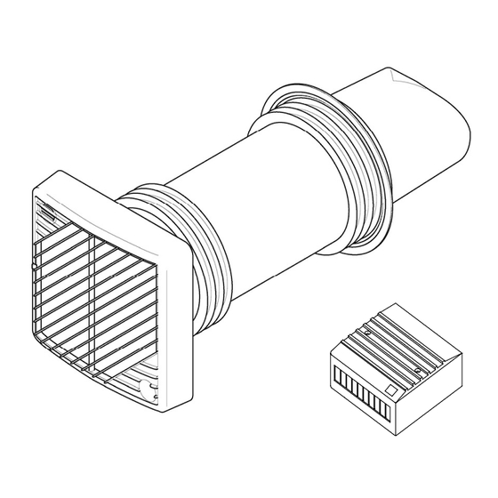
3.0 Installation Initial Preparation The unit is designed for installation in a 152mm (6”) core drilled hole. All installation can be undertaken from inside Outside Inside the building except for fixing of the external bezel if required. 1° 1. After considering the site requirements (see previous section), select a suitable position for the unit and power supply enclosure (5m maximum between unit and power supply). - Page 6 3.0 Installation 3.2 Installing the Power Supply Unit Fig.6 1. Remove the power supply unit assembly from the carton. (Fig.6) 2. Remove the power supply unit packaging. Power supply unit Located here 3. The mains input to the power supply unit must be routed via the rear of a single gang surface mounted back box (not supplied).
- Page 7 3.0 Installation Installing the HR25 1. Remove the unit, bezel and fixing pack from the carton. Filter 2. Unclip the removable grille from the unit and remove filter (Fig. 10). External Bezel 3. Loosen the two securing screws and remove Fig.
- Page 8 (Fig. 23). 14. Ensure that the low voltage cable is routed through the divider slot (Fig. 24). 15. The HR25H unit is factory set to switch between high or low speed. Two alternative SPEEDS settings can also be achieved by changing the Fig.
- Page 9 3.0 Installation Installing the HR25P 1. Remove the unit, bezel and fixing pack from the carton. Filter 2. Unclip the removable grille from the unit and remove filter (Fig. 25). External Bezel 3. Loosen the two securing screws and remove the grille surround (Fig.
- Page 10 3.0 Installation Installing the HR25P (cont) If any movement is detected after the first 2 minutes, the unit will switch to its higher setting. CON 7 SPEEDS This mode has a reset which operates after 5 minutes. Switch (A) 17. Both modes have a timer setting which CON 5 determines the length of time the unit runs for after the last movement detection.
- Page 11 3.0 Installation Installing the HR25L, LH & LP For wall thicknesses between 311mm & 425mm 1. Remove the control cover and disconnect the Control Cover red and black motor wires (Fig. 35). 2. Carefully withdraw the heat exchanger from the unit (Fig. 36). 3.
- Page 12 3.0 Installation Installing the HR25L, LH & LP (cont) Wall Thickness 25mm 5. Measure the wall thickness and add 25mm. Mounting Hole This is dimension “X” (Fig. 39). 6. Mark off dimension “X” on the outer tube, measuring from the rear of the chassis. Cut off the excess material (Fig.
-
Page 13: Maintenance
4.0 Maintenance Cleaning the Unit (all models) Filter Apart from removing odours, providing fresh air and recovering heat, this unit extracts airborne impurities such as dust, dirt and grease. These Removable Grille gradually build up and diminish from the efficiency and detract from the appearance of the unit. -
Page 14: Short Parts List
Parts List 5.0 Spares list 5.1 Spares List Key No. Description Part No. Filter (pack of 4) 370412 Heat Exchanger 372329 Power supply unit 447249 Rubber seal 371297... - Page 16 Vent-Axia guarantees its products for two years from date of purchase against faulty material or workmanship. In the event of any part being found to be defective, the product will be repaired, or at the Company’s option replaced, without charge, provided that the product:- •...
Need help?
Do you have a question about the HR25H and is the answer not in the manual?
Questions and answers